Important: To install of this kit, you must purchase and install the separate
ultra sonic boom finishing kit. Order the following finishing kit
for your machine:
|
Multi Pro 1750 Machines—finishing kit Part No. 130-8227
|
|
Multi Pro 5800 Machines—finishing kit
Part No. 130-8229
|
|
Multi Pro WM Machines—finishing kit Part No. 133-2808
|
Note: Determine the left and right sides of the machine from the normal
operating position.
Preparing the Machine
-
Clean the exterior of the machine and sprayer; refer
to the Operator’s Manual for your machine.
-
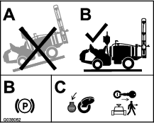
Move the machine to a level surface, shut off the
engine, set the parking brake, and remove the key.
Caution
If you leave the key in the ignition switch, someone could accidently
start the engine and seriously injure you or other bystanders.
Remove the key from the ignition switch before you install the
kit.
-
Disconnect the negative-battery cable from the battery;
refer to the Operator’s Manual for your
machine.
Assembling the Sensor Mounting Hinge
Parts needed for this procedure:
| Hinge | 2 |
| Angled strap (machines without covered booms) | 2 |
| Angled strap (machines with covered booms) | 2 |
| Top or bottom strap | 2 |
| Compression spring | 4 |
| Bushing | 8 |
| Bolt (5/16 x 3-1/4 inches) | 4 |
| Flat washer | 12 |
| Locknut (5/16 inch) | 4 |
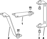
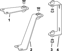
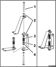
Note: Assembly of the sensor mounting hardware depends upon whether
the Covered Boom Kit (Model 41602) is installed.
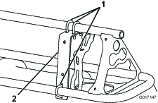
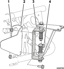
-
Lay out the hinges and straps as shown in Figure 2 (for an
uncovered boom) or Figure 3 (for a covered boom).
Note: There are 2 sets of 2 angled straps in loose parts. One set
is for an uncovered boom and the other set is for a covered boom.
You will have one set of 2 angled straps (either for the covered boom
or for the uncovered boom) that you will not use on the machine.
Note: The top straps for the uncovered booms also serve as the bottom
straps for the covered booms.
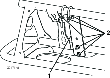
-
Insert the bushings into the welded
tube openings in the hinges and straps as shown in Figure 2 or Figure 3.
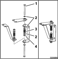
-
Install a flat washer on each of the 2 bolts (5/16
x 3-1/4 inches).
-
Insert the bolts through the hinged welded tube openings,
hinges, and straps as shown in Figure 4 or Figure 5.
-
Install a flat washer on the exposed
end of each of the bolts (Figure 4 or Figure 5).
-
Install a spring on the end of each bolt (Figure 4 or Figure 5).
-
Install a flat washer and a locknut on the end of
each bolt (Figure 4 or Figure 5), and tighten the locknuts until there is no slack
in the spring.
Note: Check to ensure that the hinges are not so tight that the mounted
sensors do not freely pivot on the hinges.
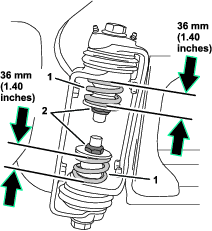
Adjusting the Boom-Hinge Springs
Important: Operating the spray system with the boom-hinge springs under
the incorrect compression could damage the boom assembly. Measure
the springs and use the jam nut to compress the springs to 36 mm (1.40
inches), if necessary.
Use another person or lifting equipment to support the boom
while adjusting the spring height of the boom hinge.
-
Extend the outer booms to the spray position (horizontal).
-
Support the booms while you are adjusting the spring
height.
-
At the pivot bracket and hinge
for the outer boom, adjust the jam nut for the upper spring until
the compressed spring height measures 36 mm (1.40 inches).
-
Adjust the jam nut for the lower
spring until the compressed spring height measures 36 mm (1.40 inches).
-
Repeat steps 3 and 4 for the upper and lower springs
at the other outer boom.
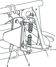
-
At the boom hinge, measure the compression of the
upper and lower springs while the booms are in the extended position
(Figure 6).
-
Compress all springs until they measure 36 mm (1.40
inches).
-
Use the jam nut to compress any spring that measures
greater than 36 mm (1.40 inches).
Adjusting the Booms
Note: You will need 2 wooden blocks about 10 cm (4 inches) in height
for this procedure.
The booms are set at the factory to travel downward no farther
than the horizontal position. To enable the ultrasonic boom kit to
maintain a consistent distance between the nozzles and the ground
when the ground slopes downward from the machine, you must adjust
the boom support system to allow the booms to travel below the horizontal
position to maintain a constant nozzle-to-ground distance.
-
Raise the booms and have them rest in the transport
cradle.
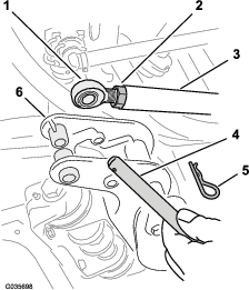
-
At the pivot brackets of the outer-boom
sections, remove the hairpin and clevis pin that secures the rod end
for the lift cylinder to the pivot bracket (Figure 7).
Note: There should be no more than 16 mm (5/8 inch) of exposed thread
on the eyelet to prevent the engaged threads from stripping and the
rod from pulling away.
-
Carefully lower the outer-boom sections onto wooden
blocks about 10 cm (4 inches) high as shown in Figure 8.
-
Start the machine and fully extend the lift cylinders.
-
Loosen the jam nuts at the rod ends for each lift
cylinder (Figure 7).
-
Adjust the rod end for the lift cylinders end until
the hole in the rod ends align with the holes in the pivot brackets
for the boom sections (Figure 7).
-
At each pivot bracket, secure the rod end to the bracket
with the clevis pin that you removed in step 2.
-
Secure the cotter pins to the pivot brackets with
the hairpin cotters (Figure 7) that you removed in step 2.
-
Tighten the jam nut at each rod until the nuts are
snug (Figure 7).
Replacing the Lift-Cylinder Manifold
Parts needed for this procedure:
| Hydraulic manifold block | 1 |
| Straight-hydraulic fitting | 4 |
Assembling the Cylinder-Lift Manifold
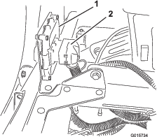
-
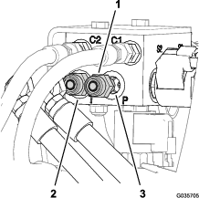
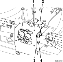
At the back of the sprayer, label the hoses at port-P
and port-T of the lift-cylinder manifold (Figure 9).
-
Remove the hoses from the straight-hydraulic fittings
at port-P and port-T of the lift-cylinder manifold (Figure 9).
-
Remove the straight-hydraulic fittings
from port-P and port-T of the old lift-cylinder manifold (Figure 9).
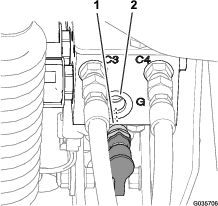
-
Remove the diagnostic fitting and
cap from port-G of the old lift-cylinder manifold (Figure 10)
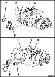
-
At the new lift-cylinder manifold, assemble the straight-hydraulic
fittings (Figure 11) that you removed in step 3 into port-P and port-T.
-
Assemble the 4 straight-hydraulic fitting from the
ultra sonic boom leveling kit into ports C1, C2, C3, and C4 of the
new lift-cylinder manifold (Figure 11).
-
Assemble the diagnostic fitting and cap that you removed
in step 4 into port-G of the new lift-cylinder manifold (Figure 11).
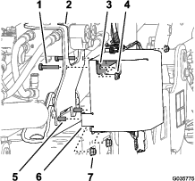
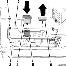
Replacing the Cylinder-Lift Manifold
-
If installed, remove the hydraulic block cover plate
from the lift-cylinder manifold.
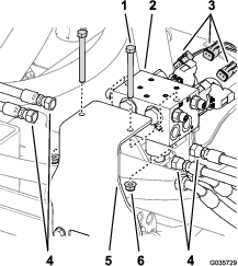
-
Label all the hoses connected to the lift-cylinder
manifold (ports C1, C2, C3, and C4), and disconnect them from the
cylinder manifold (Figure 12).
-
Disconnect the rear-wire harness connectors from the
solenoids of the lift-cylinder manifold (Figure 12).
-
Remove the lift-cylinder manifold
from the mounting bracket by removing 2 bolts and 2 locknuts (Figure 12).
Note: Save the 2 bolts and 2 locknuts.
-
Replace the mounting bracket for the lift-cylinder
manifold; refer to the installation instructions for the ultra sonic
boom finishing kit.
-
Multi Pro 1750 models—finishing
kit Part No. 130-8227
-
Multi Pro 5800 models—finishing
kit Part No. 130-8229
-
Multi Pro WM models—finishing
kit Part No. 133-2808
-
Install the new lift-cylinder manifold onto the mounting
bracket with the 2 bolts and 2 locknuts that you in step 4.
-
Install all the hoses onto the fittings of the lift-cylinder
manifold as follows:
-
The tank hose (3/8 inch) from the return filter connects
to the “T” port
-
The pressure hose (3/8 inch) connects to the “P”
port.
-
The hoses (1/4 inch) from the extend ports of the
boom-lift cylinders connect to C1 and C3 ports of the lift-cylinder
manifold.
-
The hoses (1/4 inch) from the retract ports of the
boom-lift cylinders connect to C2 and C4 ports of the lift-cylinder
manifold.
Important: Ensure that you install the hoses correctly.
-
Purge the hydraulic system. Refer to the Operator’s Manual.
Note: You will connect the wire harness from the ultra sonic boom
kit to the solenoids of the lift-cylinder manifold in Connecting the Wire Harness at the Boom-Lift Manifold.
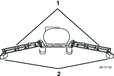
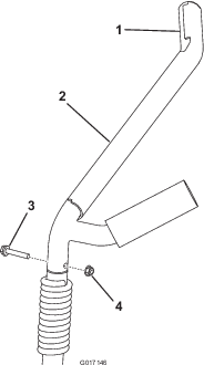
Replacing the Boom-Cradle Arms
Parts needed for this procedure:
The new boom-cradle arms allow the booms to fold up without
contacting each other, preventing any possible damage to the sensors
mounted on the booms.
-
Remove the 2 boom-cradle arms by removing the bolt
and nut (Figure 14).
Note: Save the bolts and nuts to install the new boom-cradle arms.
-
Install each new boom-cradle arm and secure it with
the bolt and nut that you previously removed.
Installing the Sonic-Boom Sensors
Parts needed for this procedure:
| Sonic-boom sensor | 2 |
| Bracket | 2 |
| Programming plug | 2 |
| Sensor cover | 2 |
| Lower sensor housing | 2 |
| Cap tube | 2 |
| Sensor-guard bracket | 2 |
| Sensor cable (4 m) | 2 |
| Large nut | 4 |
| U-bolt | 6 |
| Locknut (1/4 inch) | 8 |
| Bolt (5/16 x 3/4 inch) | 8 |
| Bolt (5/16 x 1-1/4 inches) | 4 |
| Locknut (5/16 inch) | 12 |
| Cable tie | 12 |
Installing the Sensor Mount
-
Install a mounting bracket on the
front side of each boom near the outermost nozzle (Figure 15 and Figure 16) with 3
U-bolts and 6 locknuts (1/4 inch) .
-
Install the sensor guard bracket onto the mounting
bracket with 2 bolts (5/16 x 3/4 inch) and 2 flange nuts (5/16 inch)
as shown in Figure 17.
-
Install the sensor mounting hardware
onto the sensor guard bracket with 2 bolts (5/16 x 3/4 inch) and 2
locknuts (5/16 inch) as shown in Figure 18 (for an uncovered boom) or Figure 19 (for a
covered boom).
-
Repeat steps 1 through 3 for the outer-boom section at
the other side of the machine.
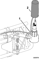
Installing the Sensor
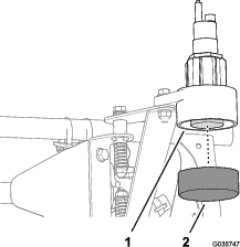
Note: Refer to Before storage for installation of the dust cap.
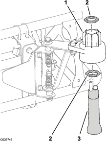
-
Install the lower sensor housing
onto the sensor mounting hardware (Figure 20) with 2 bolts (5/16 x 1-1/4
inches) and 2 locknuts (5/16 inch).
-
Install the sensor as follows:
-
Assemble a large nut onto the sensor (Figure 21).
-
Insert the sensor into the lower sensor housing (Figure 21).
-
Adjust the nut until the sensor is flush with the
bottom of the lower housing.
-
Assemble the other large nut onto the sensor (Figure 21).
-
Torque the nut to 18 to 22 N∙m (13 to 16 ft-lb).
Note: Discard the lock washers that come with the sensors.
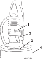
-
Install the programming plug on
the sensor (Figure 22).
Important: Ensure that you align the arrow below the sideways “T”
with the notch on the top edge of the sensor (Figure 22).
-
Repeat steps 1 through 3 for the outer-boom section at
the other side of the machine.
Installing the Wire Harness and Upper Housing
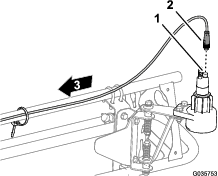
-
Connect the round 4-socket connector
of the sensor-wire harness for the 4-pin connector of the sensor (Figure 23).
-
Route the sensor-wire harness along the front of the
outer-boom section, through the support clamp, and to the 4-socket
connector of the wire harness from the ultra sonic boom finishing
kit—forward of the lift-cylinder manifold (Figure 24).
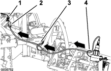
-
Connect the 4-pin connectors for the left and right
sensor-wire harnesses to the 4-socket connector of the wire harness
for the ultra sonic boom finishing kit (Figure 24) labeled LEFT
SONIC SENSOR and RIGHT SONIC SENSOR.
-
Install the upper housing over the sensor and onto
the lower housing (Figure 25).
Note: Ensure that the sensor wire is routed through the small opening
in the cover before seating the upper housing.
-
Secure the wire coming from the
sensor to the boom with cable ties (Figure 24).
Important: Allow enough slack in the wire around the sensor so that the
sensor can freely pivot on the hinge without pulling on the wire.
-
Repeat steps 1 through 5 for the outer-boom section at
the other side of the machine.
Note: For covered booms only: The sensors should
not detect the boom cover as this may interfere with the signal. If
you experience any difficulties during the calibration process, check
the sensors to ensure that their signals do not detect the boom cover.
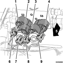
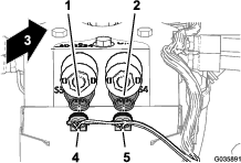
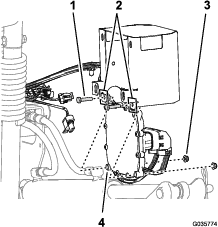
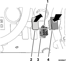
Connecting the Wire Harness at the Boom-Lift Manifold
-
At the front of the lift-cylinder manifold, connect
the 4 electrical connectors of the wire harness for the sonic boom
to the solenoids for controlling boom lift as shown in Figure 26.
-
At the back of the lift-cylinder manifold, connect
the 2 electrical connectors of the wire harness for the sonic boom
to the solenoids for controlling sonic enable as shown in Figure 27.
Mounting the Electronic Control
Parts needed for this procedure:
| Electronic controller | 1 |
| Bolt (1/4 x 1-1/8 inch) | 4 |
| Locknut (1/4 inch) | 4 |
Connecting the Wire Harness to the Electronic Controller
Multi Pro 1750 and Multi Pro WM Machines
-
Route the wire harness for the sonic boom to the hydraulic
manifold.
-
Connect the 50-socket connector of the wire harness
for the sonic boom to the 50-pin connector of the electronic controller,
and secure the connectors with the socket-head screw (Figure 28).
Note: The controller electrical connection is keyed and can be connected
only 1 way.
-
Torque the socket-head screw to 2.7 to 3.2 N-m (24
to 28 in-lb).
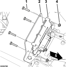
Installing the Controller to the Machine
Multi Pro 1750 and Multi Pro WM Machines
-
Align the electronic controller to the interior of
the controller cover with the lower outboard mounting holes of the
controller aligned with the holes in the lower rear flange of the
cover (Figure 29)
-
Assemble the controller to the cover with 2 bolts
(1/4 x 1-1/8 inches) and 2 flange locknuts (1/4 inch) as shown in Figure 29.
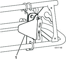
-
Remove the 2 flange locknuts (5/16
inch) that secure the mounting bracket of the ultra sonic boom finishing
kit from the cylinder mount (Figure 30).
Note: Leave the mounting bracket assembled to the cylinder mount.
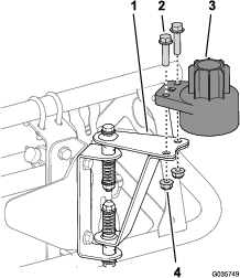
-
Assemble the controller cover (Figure 30) onto the flange-head bolt
(5/16 x 1 inch) at the lower forward holes in the cover, and loosely
secure the cover, bracket and mount with the 2 flange locknuts (5/16
inch) that you removed in 3.
-
Assemble the 2 bolts (1/4 x 1-3/8 inches) through
the upper holes in the mounting bracket (ultra sonic boom finishing
kit), rear flange (controller cover), and controller (Figure 30) with the
2 flange locknuts (1/4 inch).
-
Torque the 5/16 flange-head bolt and flange nuts to
1978 to 1243 N∙cm (175 to 225 in-lb).
-
Torque the 1/4 flange-head bolt and flange nuts to
1017 to 2542 N∙cm (90 to 110 in-lb).
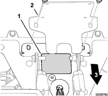
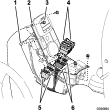
Installing the Controller to the Machine
Multi Pro 5800 Machines
-
Rotate the operator and passenger seats forward and
secure the seats with the prop rods.
-
For 2015 and before machines—locate the knockout plug between the inboard operator and
passenger seat-belt halves, and remove the knockout plug from the
console base (Figure 32).
-
Assemble the electronic controller to the mounting
bracket (Figure 32) with the 4 bolts (1/4 x 1-1/8 inch) and 4 locknuts (1/4 inch).
-
Torque the nuts and bolts to 1017 to 1243 N∙cm (90
to 110 in-lb)
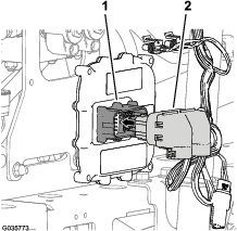
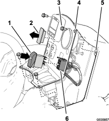
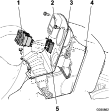
Connecting the Wire Harness to the Electronic Controller
Multi Pro 5800 Machines
-
Route the 50-socket connector of the wire harness
for the sonic boom as follows:
-
For 2015 and before machines—the
branch of the wiring harness with the 50-socket connector is routed
through the opening in the console base that you made in step 2; refer to
the installation instructions for the ultra sonic boom finishing kit.
-
For 2015 and after machines—the
branch of the wiring harness with the 50-socket connector is routed
through the large grommet in the console base; refer to the installation
instructions for the ultra sonic boom finishing kit.
-
Connect the 50-socket connector of the wire harness
for the sonic boom to the 50-pin connector of the electronic controller,
and secure the connectors with the socket-head screw (Figure 33).
Note: The electrical connection for the controller is keyed and can
be connected only 1 way.
-
Torque the socket-head screw to 2.7 to 3.2 N-m (24
to 28 in-lb).
Connecting the Wiring Harness and Switches
Parts needed for this procedure:
| Rocker switch (illuminated) | 1 |
| Cable tie | 12 |
Installing the Ultra Sonic-Mode Switch
Multi Pro 1750 Machines
-
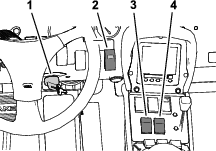
If installed, remove the 4 flange-head
bolts (1/4 x 1/2 inch) that secure the panel cover to the top of the
console as shown in Figure 34.
-
Remove the switch plug from the panel cover of the
console (Figure 34).
-
Align the 8-socket connector of the wiring harness
of the ultra sonic boom finishing kit through the opening in panel
cover (Figure 34).
-
Connect the 8-socket connector of the wiring harness
of the ultra sonic boom finishing kit labeled SONIC MODE
MANUAL VS. AUTO to the rocker switch (Figure 34).
-
Insert the rocker switch in the dash panel opening
until the switch snaps securely (Figure 34).
-
Align the holes in the panel cover to the holes in
the top of the console (Figure 34).
-
Secure the panel to the console with the bolts (Figure 34) that you
removed in step 1.
Installing the Ultra Sonic-Mode Switch
Multi Pro 5800 Machines
-
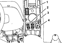
Remove the switch plug in the dash panel at the location
shown in Figure 35.
-
Connect the 8-socket connector of the wiring harness
of the ultra sonic boom finishing kit labeled SONIC MODE
MANUAL VS. AUTO to the rocker switch (Figure 35).
-
Insert the rocker switch in the dash panel opening
until the switch snaps securely (Figure 35).
Note: Align the tail of the switch down.
Installing the Ultra Sonic-Mode Switch
Multi Pro WM Machines
-
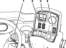
If installed, remove the 4 flange-head
bolts (1/4 x 1/2 inch) that secure the control panel to the console
as shown in Figure 36.
-
Remove the switch plug from the control panel of the
console (Figure 36).
-
Align the 8-socket connector of the wiring harness
of the ultra sonic boom finishing kit through the opening in control
panel (Figure 36).
-
Connect the 8-socket connector of the wiring harness
of the ultra sonic boom finishing kit labeled SONIC MODE
MANUAL VS. AUTO to the rocker switch (Figure 36).
-
Insert the rocker switch in the control panel opening
until the switch snaps securely (Figure 36).
Note: Align the tail of the switch down.
-
Align the holes in the control panel to the holes
in the top of the console (Figure 36).
-
Secure the panel to the console with the bolts (Figure 36) that you
removed in step 1.
Connecting the Boom-Lift Switches to the Sonic-Boom Harness
Connecting the Switches to the Harness
Multi Pro 1750 or Multi Pro WM Machines
-
Remove the 4 flange-head bolts
(1/4 x 1/2 inch) that secure the switch panel to the center console,
and lift the panel (Figure 37 or Figure 28).
-
Disconnect the 8-socket connectors of the machine-wire
harness from the boom-lift switches (Figure 37 or Figure 38).
Note: If additional clearance is needed, remove the boom-lift switches
from the switch panel.
-
Connect the rocker switches into the 8-socket connectors
of the wiring harness for the ultra sonic boom finishing kit (Figure 37 or Figure 38).
Note: Ensure that the sonic-boom harness connector labeled LEFT ACTUATOR SWITCH is aligned with the left switch
opening in the switch panel.
-
If you removed the switch(es) from the switch panel,
insert the boom-lift switch(es) into the openings in the center-console
panel until the switch(es) snaps securely.
-
Align the holes in the switch panel with the frame
of the console (Figure 37 or Figure 38).
-
Secure the side cover on the center console with the
4 flange-head bolts (1/4 x 1/2 inch) (Figure 37 or Figure 38) that you removed in step 1.
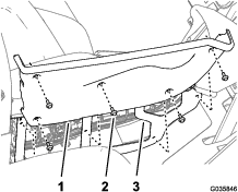
Connecting the Switches to the Harness
Multi Pro 5800 Machines
-
Remove the 5 flange-head bolts
(1/4 x 3/4 inch) that secure the right-side cover to the center console
(Figure 39).
-
Remove the rocker switches for the left and right
boom-lift controls from the center-console panel (Figure 39).
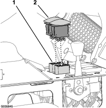
-
Disconnect the 8-socket connectors of the wiring harness
for the machine from the boom-lift switches for the left and right
boom-lift control circuits (Figure 40).
Note: Tuck the connectors for the wire harness for the machine alongside
the harness.
-
Connect the rocker switches into the 8-socket connectors
of the wiring harness for the ultra sonic boom finishing kit (Figure 40).
Note: Ensure that the sonic-boom harness connector labeled LEFT ACTUATOR SWITCH is aligned with the left switch
opening in the center-console panel.
-
Insert the boom-lift switches in the openings in the
center-console panel until the switches snap securely (Figure 40).
-
Align the holes in the right-side cover with the frame
of the center console (Figure 39).
-
Secure the side cover on the center console (Figure 39) with the
5 flange-head bolts (1/4 x 3/4 inch) that you removed in step 1.
Finishing Installation of the Ultra Sonic Boom Leveling Kit
-
Connect the negative-battery cable to the battery;
refer to the Operator’s Manual for your
machine.
-
For Multi Pro 1750 and Multi Pro 5800 machines, rotate
down the seats.
Calibrating the Sonic Booms
Once you initiate the controller processor for calibration,
you will have 20-seconds to calibrate the sensors on the booms. The
distance you set between the sensor on each boom and the ground after
the 20-second calibration period is the boom height setting in automatic
mode until the next time you calibrate the sensor.
Note: For uncovered booms: The default height
setting is 51 cm (20 inches) from the nozzle to the ground. If, after
setting a boom to a height different from that of the factory default
setting, you wish to restore the calibration to the factory-default
setting, calibrate the boom with the boom in the cradle. For covered booms: The default height setting of 51 cm
(20 inches) is for uncovered booms only. You must calibrate the sensors
on covered booms.
-
Ensure that the turf sprayer is parked and away from
any trees, buildings, vehicles, debris, and underground utilities
and plumbing.
-
Lower the booms to the horizontal position.
-
Turn off the ignition key.
-
Press the sonic-boom switch to the ON position (Figure 41, Figure 42, or Figure 43).
-
While pressing and holding both the left boom-lift
control switch to the LOWER position and
the right boom-lift control switch to the RAISE position, turn the ignition key and start the machine.
-
Release the boom switches.
Note: The indicator light on the sonic-boom switch will flash rapidly,
indicating that the sonic boom system is in calibration mode. You
now have 20 seconds to use the Raise and Lower boom switches to set
the desired distance between the booms to the ground. After the 20
seconds, the indicator light flashes slowly.
-
Raise and lower the outer-boom sections using the
boom-lift control switches to adjust the height of each boom until
you achieve the desired distance between the tip of the boom and the
ground.