Safety

Rollover Protection System (ROPS) Safety

  • The ROPS is an integral safety device. Do not remove any of the ROPS components from the machine.

  • Ensure that the seat belt is attached and that you can release it quickly in an emergency.

  • Keep the roll bar in the fully raised and locked position and always wear your seat belt whenever the roll bar is up.

  • Check carefully for overhead objects before you drive under them, and do not contact them.

  • Replace damaged ROPS components. Do not repair or alter them.

  • There is no rollover protection when the roll bar is down.

  • Wheels dropping over edges, over steep banks, or into water can cause a rollover, which may result in serious injury or death.

  • Do not wear the seat belt when the roll bar is down.

  • Lower the roll bar only when absolutely necessary; raise it as soon as clearance permits.

  • In the event of a rollover, take the machine to an Authorized Service Dealer to inspect the ROPS.

  • Use only Toro approved accessories and attachments for the ROPS.

Safety and Instructional Decals

Graphic

Safety decals and instructions are easily visible to the operator and are located near any area of potential danger. Replace any decal that is damaged or missing.

decal107-3069

Installation

Preparing the Machine

Note: Determine the left and right sides of the machine from the normal operating position.

  1. Park the machine on a level surface.

  2. Disengage the blade-control switch.

  3. Move the motion-control levers outward to the PARK position.

  4. Shut off the machine and remove the key.

  5. Wait for all moving parts to stop.

  6. Allow machine components to cool.

  7. Non-MyRide models only: Raise the seat; refer to your machine Operator’s Manual.

  8. MyRide models only: Perform the following steps to remove the seat.

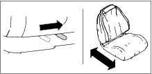
    1. Use the seat position lever to slide the seat forwards and backwards (Figure 1).

      g471967
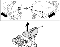
    2. Access the 4 Torx bolts that secure the seat pan to the frame. Remove the bolts, then carefully remove and set aside the seat assembly (Figure 2).

      g471954
  9. Raise the rear of the machine on jack stands; refer to your machine Operator’s Manual.

    Warning

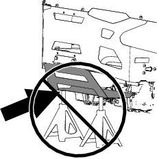
    Supporting the machine on the lower muffler shield (Figure 3) may damage the shield and cause the machine to fall, injuring you or bystanders.

    Do not use the lower muffler shield to support the machine.

    g471762
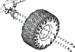
  10. Remove the rear tires as shown in Figure 4

    Note: Retain all wheel components for later installation.

    g464562

Installing the ROPS Mounts and Lower Roll Bar

Parts needed for this procedure:

Left ROPS mount1
Right ROPS mount1
Hex-head bolt (1/2 x 2-1/2 inches)4
Locknut (1/2 inch)8
Left lower roll-bar tube1
Right lower roll-bar tube1
Hex-head bolt (1/2 x 3-1/2 inches)4
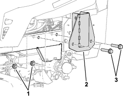
  1. Install the ROPS mount to the machine frame above the axle as shown in Figure 5. Repeat on the other side.

    g471982
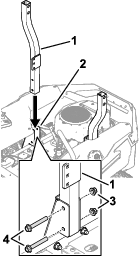
  2. Lower a lower roll-bar tube into the ROPS mount and secure with 2 hex-head bolts (1/2 x 3-1/2 inches) and 2 locknuts (1/2 inch) as shown in Figure 6. Repeat on the other side.

    g472039
  3. Torque the bolts in steps 1 and 2 to 91 to 113 N∙m (67 to 83 ft-lb).

Installing the Seat Belt

MyRide-Equipped Models Only

Parts needed for this procedure:

Left seat-belt bracket (MyRide models only)1
Right seat-belt bracket (MyRide models only)1
Partial-thread bolt (3/8 x 2 inches)2
Washer2
Locknut (3/8 inch)2
Seat belt-buckle assembly1
Seat belt-tongue assembly1
Carriage bolt (7/16 x 1 inch)2
Locknut (7/16 inch)2
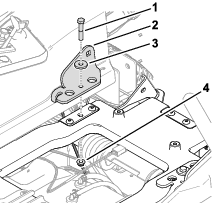
  1. Install the seat-belt brackets to the seat platform with 2 partial-thread bolts (3/8 x 2 inches), 2 washers, and 2 locknuts (3/8 inch) as shown in Figure 7. Repeat on the other side.

    g472007
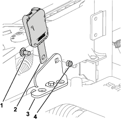
  2. Install the seat belt-buckle and tongue assemblies to the seat-belt brackets using 2 carriage bolts (7/16 x 1 inch) and 2 locknuts (7/16 inch) as shown in Figure 8. Repeat on the other side for the tongue assembly.

    g473057

Installing the Seat Belt

Non-MyRide Models Only

Parts needed for this procedure:

Seat belt-buckle assembly1
Seat belt-tongue assembly1
Seat belt-buckle bracket (non-MyRide models only)1
Seat belt-tongue bracket (non-MyRide models only)1
Hex-head bolt (1/2 x 1 inch)2
Locknut (1/2 inch)6
Carriage bolt (3/8 x 1 inch)4
Locknut (3/8 inch)4
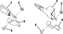
  1. Assemble the seat belts by attaching the buckle and tongue to the inside of the seat-belt brackets using 2 hex-head bolts (1/2 x 1 inch) and 2 locknuts (1/2 inch) as shown in Figure 9.

    g471783
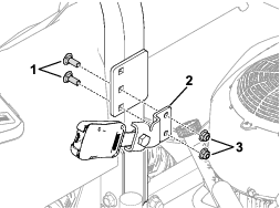
  2. Install the buckle assembly from step 1 to the inside of the roll bar bracket using 2 carriage bolts (3/8 x 1 inch) and 2 locknuts (3/8 inch) as shown in Figure 10. Repeat on the other side for the tongue assembly.

    g472041

Installing the Upper Roll Bar

Parts needed for this procedure:

Upper roll bar1
Bumper2
Shoulder bolt2
Wave washer2
Latch-pin assembly2
Locknut (1/2 inch)2
  1. Install the rear tires as shown in Figure 4.

  2. Lower the machine; refer to your machine Operator’s Manual.

  3. Lower or install the seat; refer to Preparing the Machine.

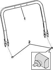
  4. Locate the upper roll bar tube. Install 2 rubber bumpers (Figure 11).

    g471996
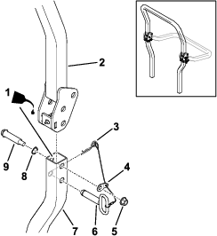
  5. Lightly oil the inside surfaces of the lower roll bar tubes (Figure 12).

  6. Loosely install the upper roll bar to the lower roll bar using 2 shoulder bolts, 2 wave washers, 2 washer tabs attached to lanyards, and 2 locknuts (1/2 inch) as shown in Figure 12.

    Note: Ensure that the shoulder bolts are installed with the bolt heads to the inside of the roll bar.

    Note: Ensure that the washer tabs are installed and pointed towards the rear of the machine.

    g472044
  7. Torque the shoulder bolts to 91 to 113 N∙m (67 to 83 ft-lb).

  8. Raise the upper roll bar into the upright position, install the latch pins (the oval handles must be on the outside of the machine), and secure with hairpin cotters on each side (Figure 12).

Installing Additional Weights

Machines Equipped with a Bagger Kit Only

Parts needed for this procedure:

Suitcase weight (machines equipped with a bagger kit only)1

For machines equipped with a bagger kit only: Install the included additional suitcase weight to the machine using 2 bolts (3/8 x 2-3/4 inches) as shown in Figure 13.

Refer to the following table for the necessary number of weights required for each model and deck size:

g467410
TimeCutter Max models
Deck SizeTotal Weights Required
60 inch4
54 inch5
50 inch5
42 inch7
Titan models
Deck SizeTotal Weights Required
60 inch2
54 inch3
48 inch4

Important: Whenever you remove the bagger attachment, remember to remove the front weights to return the proper stability to the machine.

Maintenance

Checking the Seat Belt

Maintenance Service IntervalMaintenance Procedure
Before each use or daily
  • Check the seat belt.
  • Inspect the seat belt for wear, cuts, and proper operation of the retractor and buckle. Replace the seat belt if it is damaged.

    Checking the Rollover Protection System (ROPS)

    Maintenance Service IntervalMaintenance Procedure
    Before each use or daily
  • Check the seat belt.
  • Visually inspect the ROPS for loose hardware or any other possible problem. Tighten the hardware or correct the problem before operating.