Installation
Preparing the Machine
-
Park the machine on a level surface.
-
Disengage the blade-control switch.
-
Move the motion control levers outward to the PARK position.
-
Shut off the engine and remove the key.
Assembling the Assist Handle
Installing the Assist-Handle Bracket
Parts needed for this procedure:
| Assist-handle bracket | 1 |
| Hex flange-head bolt (thread-forming—5/16 x 3/4 inch) | 2 |
Measuring and Drilling Holes into the Frame Rail
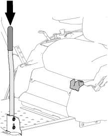
-
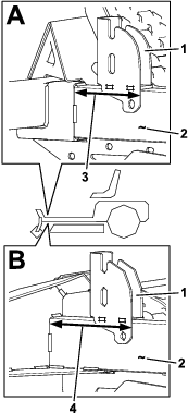
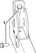
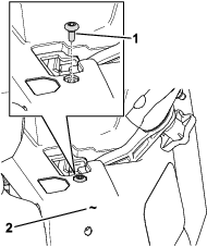
Hold the assist-handle bracket against the left frame rail and position it according to the measurement for your particular model (Figure 2).
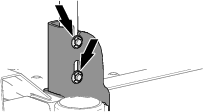
-
Using the assist-handle bracket as a template, draw marks through the holes onto the frame rail (Figure 3).
-
Drill holes at the marked locations using a drill bit (9/32 inch) as shown in Figure 3.
Warning
Using a drill without proper eye protection may allow debris to enter the eye, causing injury.
When drilling, always wear eye protection.
Securing the Bracket to the Frame Rail
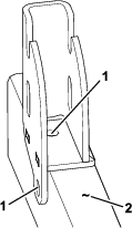
Secure the bracket to the side of the left frame rail using 2 thread-forming hex flange-head bolts.
Installing the Assist Handle
Parts needed for this procedure:
| Pin (grooved) | 1 |
| Washer (3/8 inch) | 1 |
| Retaining ring | 1 |
-
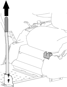
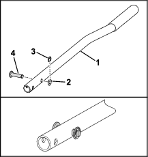
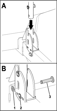
Align the lower hole in the assist handle with the closed slot in the assist-handle bracket as shown in Figure 5.
-
Assemble the grooved pin through the slot in the bracket and the hole in the assist handle (Figure 5).
-
Secure the pin to the bracket and handle with the washer (3/8 inch) and the retaining ring (Figure 5).
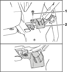
Installing the Handle Retainer
Parts needed for this procedure:
| Handle retainer | 1 |
| Shoulder screw (1/4 x 1/2 inch) | 1 |
Operation
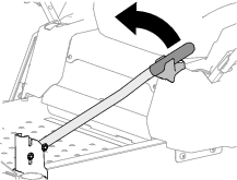
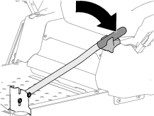
Extending the Assist Handle
Rotate the assist handle to the extend position when the machine is stationary and you are getting on and off the machine.