
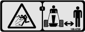
 , which means Caution, Warning,
or Danger—personal safety instruction. Failure to comply with
these instructions may result in personal injury or death.
, which means Caution, Warning,
or Danger—personal safety instruction. Failure to comply with
these instructions may result in personal injury or death.


Maintenance
Recommended Maintenance Schedule(s)
| Maintenance Service Interval | Maintenance Procedure |
|---|---|
| Before each use or daily |
|
| Every 40 hours |
|
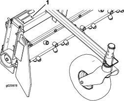
Checking the Tire Pressure
| Maintenance Service Interval | Maintenance Procedure |
|---|---|
| Before each use or daily |
|
Maintain the air pressure in the tires, as uneven tire pressure can cause uneven raking.
Check the tires when they are cold to get the most accurate pressure reading.
If the tire pressure is low, inflate the tire(s) to 345 kPa (50 psi).
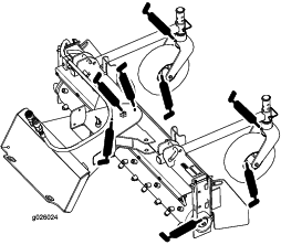
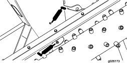
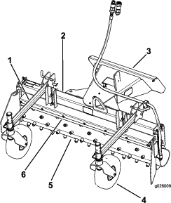
Greasing the Power Rake
| Maintenance Service Interval | Maintenance Procedure |
|---|---|
| Every 40 hours |
|
Grease Type: No. 2 general purpose, lithium-base grease
-
Turn off the engine, set the parking brake, and remove the key from the ignition of the traction unit.
-
Place the power rake on a level surface.
-
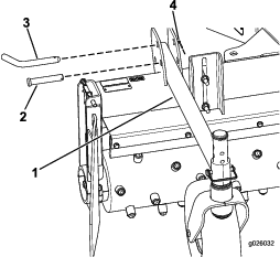
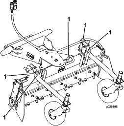
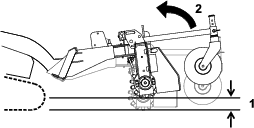
Clean the grease fittings with a rag.
Note: Make sure to scrape any paint off the front of the fitting(s).
-
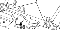
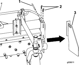
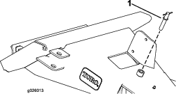
Apply the necessary amount of grease to the grease fittings (Figure 11 and Figure 12).