Important: Install the Auxiliary Wire Harness Kit (Toro Part Number 139-1186;
sold separately) before installing this kit.
Preparing the Machine
Note: Determine the left and right sides of the machine from the normal
operating position.
-
Park the traction unit on a level surface.
-
Disengage the auxiliary hydraulics.
-
Lower any equipped attachments; refer to your Operator’s Manual.
-
Engage the traction unit parking brake.
-
Shut off the traction unit engine and remove the key.
-
Wait for the traction unit to cool.
-
Disconnect the traction unit battery; refer to your Operator’s Manual.
Installing the Hydraulic Angle
Parts needed for this procedure:
| Manifold assembly | 1 |
| Bolt (3/8 x 1 inch) | 3 |
| Lock washer | 3 |
| Flat washer | 3 |
| Hose clamp | 1 |
| Bolt (5/16 x 1-1/2 inches) | 1 |
| Long hose | 1 |
| Short hose | 1 |
| Hydraulic cylinder assembly | 1 |
| Pivot pin | 2 |
| Snap ring | 4 |
| Large washer | 4 |
| 14-pin wire harness | 1 |
| Y-adapter | 1 |
Important: You may discard all removed parts unless otherwise noted.
Warning
Seek immediate medical attention if fluid is injected into skin.
Injected fluid must be surgically removed within a few hours by a
doctor.
-
Ensure that all hydraulic-fluid hoses and lines are
in good condition and all hydraulic connections and fittings are tight
before applying pressure to the hydraulic system.
-
Keep your body and hands away from pinhole leaks or
nozzles that eject high-pressure hydraulic fluid.
-
Use cardboard or paper to find hydraulic leaks.
-
Safely relieve all pressure in the hydraulic system
before performing any work on the hydraulic system.
-
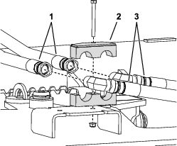
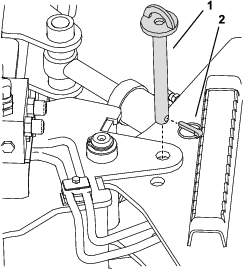
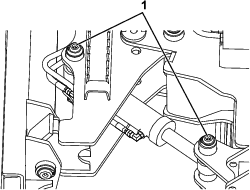
Mark each of the hoses as left or right (from the
operator’s position).
-
Remove the nut and bolt securing the hose clamp to
the hose mount (Figure 1).
-
Disconnect the power rake motor hoses from the attachment
hoses at the angle fitting (Figure 1).
-
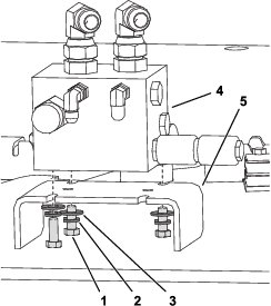
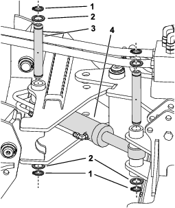
Secure the manifold assembly to the hose mount with
3 bolts (3/8 x 1 inch), lock washers and flat washers (Figure 2).
Note: Secure the manifold with the angled fittings facing toward the
front of the rake.
-
Torque the bolts securing the manifold to 37 to 45
N∙m (27 to 33 ft-lb).
-
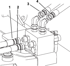
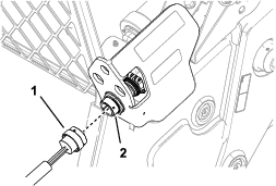
Install the attachment hoses directly to the straight
fittings in the rear of the manifold assembly (Figure 3).
Important: Install the hose connections so that they are secure, but do
not tighten any of these connections until Completing the Installation.
-
Remove the angle fittings from the power rake hoses
and install the hose ends to the angled fittings on top of the manifold
assembly (Figure 3).
Important: Do not twist or cross the hoses. Retain the orientation of the
hoses on the valve as they were in the clamp.
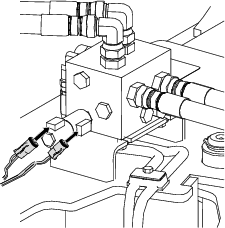
-
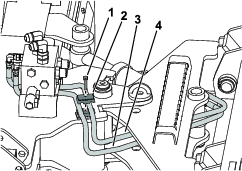
Install the long and short hoses to the manifold,
then route the hoses under the manifold and install the hose clamp
as shown in Figure 4 and Figure 6.
-
Remove the angle pin and the lynch pin that are securing
the power rake from angling (Figure 5).
-
Align the hydraulic cylinder assembly as shown in Figure 6.
Note: You may need to angle the power rake manually to match the cylinder
length.
-
Install a pivot pin at each end of the cylinder with
2 large washers and snap rings at each end of the pivot pins (Figure 6).
-
Use the auxiliary hydraulic controls to adjust the
angle of the power rake.
-
Install the 14-pin wire harness (short wire harness)
to the auxiliary wire harness (sold separately) at the coupler mount
(Figure 7).
-
Install the open connector of the Y-adapter (long
wire harness) to the 14-pin wire harness.
-
Route the 2 free connectors on the Y-adapter to the
open connectors left side of the manifold and connect them (Figure 8).
Note: Secure the wire harness using cable ties as needed.
Completing the Installation
-
Tighten the larger hose connections at the top and
rear of the manifold to 115 to 127 N∙m (85 to 94 ft-lb).
Note: When tightening a hose connection to a fitting, always use 2
wrenches; 1 wrench on the hose flats so that the hose does not twist,
and the other wrench on the hose nut to secure the hose to the fitting.
-
Tighten the smaller hose connections at the front
of the manifold to 24 to 27 N∙m (18 to 20 ft-lb).
-
Lubricate the cylinder grease fittings; refer to Lubricating the Hydraulic Angle.
-
Connect the traction unit battery; refer to your traction
unit Operator’s Manual.
-
Turn on the traction unit and test the hydraulic angle
operation.
Important: To operate the cylinder, flow must be running to the attachment.
While flow is running, operate the cylinder using the secondary attachment
function on the joystick.
Note: If the hydraulic angle is not operating correctly, ensure that
the hoses are connected to the correct ports.
-
If any hydraulic fluid was spilled, ensure that the
traction unit hydraulic fluid is at the correct level; refer to your Operator’s Manual.
-
Use the auxiliary hydraulic controls to adjust the
angle of the power rake.