Intended Use
This rotary-blade, riding lawn mower is intended to be used by homeowners in residential applications. It is designed primarily
for cutting grass on well-maintained lawns. Using this product for purposes other than its intended use could prove dangerous
to you and bystanders.
Read this information carefully to learn how to operate and maintain your product properly and to avoid injury and product
damage. You are responsible for operating the product properly and safely.
Getting Help
Visit www.Toro.com for product safety and operation training materials, accessory information, help finding a dealer, or to register your product.
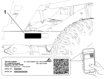
Whenever you need service, genuine Toro parts, or additional information, contact an Authorized Service Dealer or Toro Customer Service and have the model and serial numbers of your product ready. These numbers are located on the serial plate
on your product  . Write the numbers in the space provided.
With your mobile device, you can scan the QR code on the serial number decal (if equipped) to access warranty, parts, and
other product information.
|
Model Number:
|
|
Serial Number:
|
|
Manual Conventions
This manual identifies potential hazards and has safety messages identified by the safety-alert symbol, which signals a hazard
that may cause serious injury or death if you do not follow the recommended precautions.
This manual uses 2 words to highlight information. Important calls attention to special mechanical information and Note emphasizes general information worthy of special attention.
Safety Alert Classifications
The safety-alert symbol shown in this manual and on the machine identifies important safety messages that you must follow
to prevent accidents.
Safety-alert symbol appears above information that alerts you to unsafe actions or situations and is followed by the word
DANGER, WARNING, or CAUTION.
 |
Danger |
|
Danger indicates an imminently hazardous situation which, if not avoided, will result in death or serious injury.
|
Warning |
|
Warning indicates a potentially hazardous situation which, if not avoided, could result in death or serious injury.
|
Caution |
|
Caution indicates a potentially hazardous situation which, if not avoided, may result in minor or moderate injury.
General Safety
This product is capable of amputating hands and feet and of throwing objects. Always follow all safety instructions to avoid
serious personal injury or death.
- Read, understand, and follow the instructions and warnings in this Operator’s Manual and on the machine, engine, and attachments before starting the engine.
- Do not allow children or untrained people to operate or service the machine. Allow only people who are responsible, trained,
familiar with the instructions, and physically capable to operate or service the machine.
- Keep bystanders, particularly children, away from the operating area.
- Do not operate the machine near drop-offs, ditches, embankments, water, or other hazards, or on slopes greater than 15°.
- Do not put your hands or feet near moving parts.
- Do not operate the machine without all safety shields, guards, switches, and other devices in place and working properly.
- Park the machine on a level surface, disengage the drives, engage the parking brake, shut off the engine, remove the key,
and wait for all moving parts to stop before leaving the operator’s position.
- Wait for the machine to cool before servicing, adjusting, fueling, cleaning, or storing it.
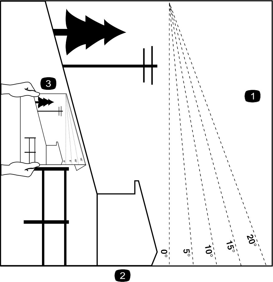
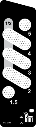
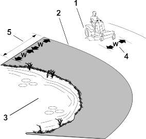
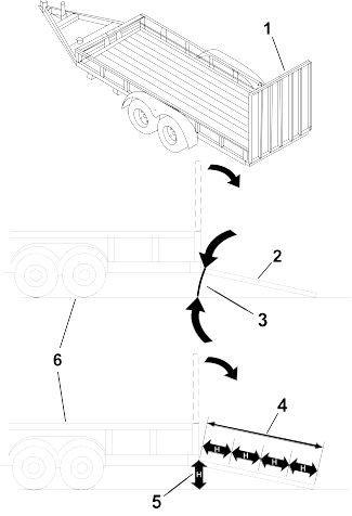
Slope Indicator
You may copy this page for personal use.
G011841s
-
The maximum slope you can operate the machine on is 15 degrees. Use the slope chart to determine the degree of slope of hills
before operating. Do not operate this machine on a slope greater than 15 degrees. Fold along the appropriate line to match the recommended slope.
-
Align this edge with a vertical surface, a tree, building, fence pole, etc.
-
Example of how to compare slope with folded edge
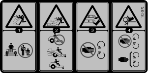
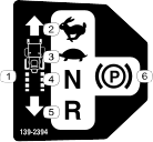
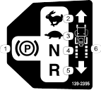
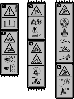
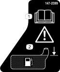
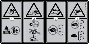
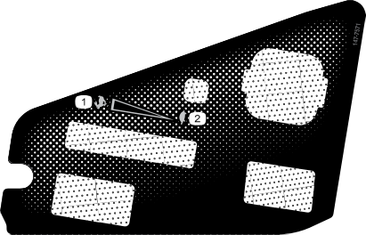
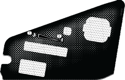
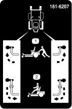
Safety and Instructional Decals
 |
Safety decals and instructions are easily visible to the operator and are located near any area of potential danger. Replace
any decal that is damaged or missing.
|
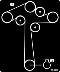
Decal Part: 99-3943
Models 77503, 77504, and 77601 only
Decal Part: 130-0731
Models 77503, 77504, and 77601 only
Decal Part: 132-0872
Models 77503, 77504, and 77601 only
Decal Part: 144-5288
Note: This machine complies with the industry standard stability test in the static lateral and longitudinal tests with the maximum
recommended slope indicated on the decal. Review the instructions for operating the machine on slopes in the Operator’s Manual as well as the conditions in which you would operate the machine to determine whether you can operate the machine
in the conditions on that day and at that site. Changes in the terrain can result in a change in slope operation for the machine.
Decal Part: 147-3023
Models 77506, 77507, and 77603 only
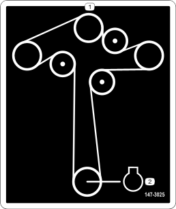
Decal Part: 147-3025
Models 77506, 77507, and 77603 only
Decal Part: 147-5152
Models 77506, 77507, and 77603 only
Decal Part: 147-7571
Models with an hour meter only
Decal Part: 147-7574
MyRIDE models only
Decal Part: 147-8753
Models without an hour meter only
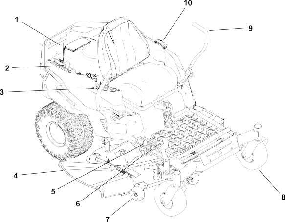
G454341
-
Engine
-
MyRide® suspension adjustment lever (machines with MyRide suspension only)
-
Control panel
-
Deflector
-
Height-of-cut pin
-
Deck-lift pedal
-
Anti-scalp roller
-
Front caster wheel
-
Motion-control lever
-
Fuel-tank cap
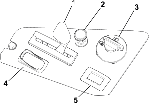
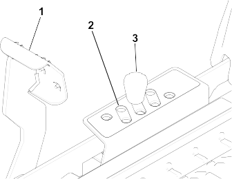
Control Panel
G453238
- Throttle control
- Choke control
- Key switch
- Blade-control switch (power takeoff)
- Hour meter (certain models only)
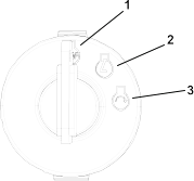
Key Switch
Use the key switch to start or shut off the machine.
G375755s
- Shut off the engine
- Run the engine
- Start engine
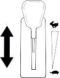
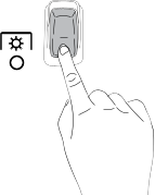
Throttle Control
The throttle controls the engine speed, and it has a continuous-variable setting from the Slow to Fast position.
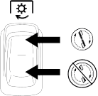
Blade-Control (PTO) Switch
The blade-control switch, represented by a power-takeoff (PTO) symbol, engages and disengages power to the mower blades.
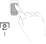
Choke Control
Use the choke control to aid in starting a cold engine.
G419508
-
Engaged
-
Disengaged
Hour Meter
For Machines with an Hour Meter
The hour meter records the number of hours the engine is running. Use these times for scheduling regular maintenance.
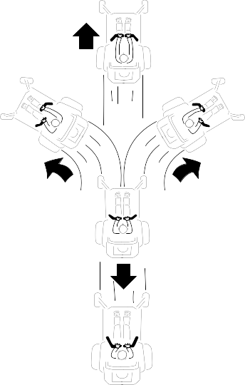
Motion-Control Levers
Use the motion-control levers to drive the machine forward, reverse, and turn either direction.
Park Position
Move the motion-control levers outward from the center to the Park position to engage the parking brake when stopping or exiting the machine.
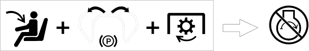
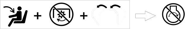
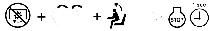
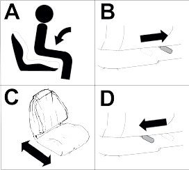
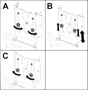
MyRide® Suspension Adjustment Lever
For Machines with the MyRide Suspension System
Use the adjustment lever to adjust the seat suspension for a smooth and comfortable ride.
G292102s
- Adjustment lever
- Softer suspension
- Firmer suspension
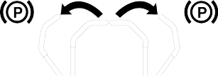
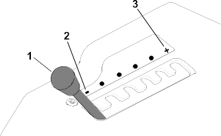
Height-of-Cut Pin
The height-of-cut pin works with the foot pedal to lock the deck in a specific cutting height. Adjust the height of cut only
when the machine is not moving.
Deck-Lift Pedal
Use the deck-lift pedal to briefly raise the mower deck from the seated position to avoid obstacles or when adjusting the
height of cut.
Specifications
Note: Specifications and design are subject to change without notice.
|
Cutting width
|
134 cm (54 inches)
|
134 cm (54 inches)
|
152 cm (60 inches)
|
152 cm (60 inches)
|
|
Width with deflector down
|
166 cm (65-1/2 inches)
|
166 cm (65-1/2 inches)
|
182 cm (71-1/2 inches)
|
182 cm (71-1/2 inches)
|
|
Width with deflector up
|
140 cm (55 inches)
|
140 cm (55 inches)
|
155 cm (61 inches)
|
155 cm (61 inches)
|
|
Length
|
203 cm (80 inches)
|
203 cm (80 inches)
|
203 cm (80 inches)
|
203 cm (80 inches)
|
|
Height
|
119 cm (47 inches)
|
116 cm (45-1/2 inches)
|
116 cm (45-1/2 inches)
|
119 cm (47 inches)
|
|
Weight
|
313 kg (689 lb)
|
294 kg (649 lb)
|
303 kg (668 lb)
|
318 kg (702 lb)
|
Attachments/Accessories
A selection of Toro approved attachments and accessories is available for use with the machine to enhance and expand its capabilities. Contact
your Authorized Service Dealer or authorized Toro distributor or go to www.Toro.com for a list of all approved attachments and accessories.
To ensure optimum performance and continued safety certification of the machine, use only genuine Toro replacement parts and accessories.
Maintenance Safety
- If you leave the key in the switch, someone could accidently start the engine and seriously injure you or other bystanders.
Remove the key from the switch before you perform any maintenance.
- Before you leave the operator’s position, do the following:
- Park the machine on a level surface.
- Disengage the drives.
- Engage the parking brake.
- Shut off the engine and remove the key.
- Wait for the machine to cool before performing maintenance.
- Do not allow untrained personnel to service the machine.
- Keep your hands and feet away from moving parts or hot surfaces. If possible, do not make adjustments with the engine running.
- Keep all guards, shields, switches, and all safety devices in place and in proper working condition. Frequently check for
worn or deteriorating components and replace them with genuine Toro parts when necessary.
- Carefully release pressure from components with stored energy.
|
Warning |
|
Removing or modifying original equipment, parts, and/or accessories may alter the warranty, controllability, and safety of
the machine. Making unauthorized modifications to the original equipment or failing to use original Toro parts could lead to serious injury or death.
- Check the parking brake operation frequently. Adjust and service it as required.
- Never tamper with safety devices. Check their proper operation regularly.
- Clean grass, leaves, excessive grease and oil, and other debris from the cutting unit, muffler, drives, grass catcher, and
engine compartment to prevent fires.
- Clean up oil or fuel spills and remove fuel-soaked debris.
- Do not rely solely on mechanical or hydraulic jacks to support the machine. Use adequate jack stands.
- Keep all parts in good working condition and all hardware tightened, especially the blade-attachment hardware.
- To ensure optimum performance, use only genuine Toro replacement parts and accessories. Replacement parts and accessories made by other manufacturers could be dangerous.
Recommended Maintenance Schedule
|
After the first 8 hours
|
Change the engine oil.
|
|
After the first 50 hours
|
Check the lug-nut torque.
|
|
Before each use or daily
|
Check the safety-interlock system.
|
|
Check the air cleaner for dirty, loose, or damaged parts.
|
|
Check the engine-oil level.
|
|
Clean the air-intake screen.
|
|
Inspect the blades.
|
|
Inspect the grass deflector for damage.
|
|
After each use
|
Clean grass and debris from the machine.
|
|
Clean the mower-deck housing.
|
|
Every 25 hours
|
Grease the caster wheel bearings (more often in sandy soil conditions).
|
|
Check the tire pressure.
|
|
Check the belts for wear or cracks.
|
|
Every 100 hours
|
Change the engine oil (more often in dirty or dusty conditions).
|
|
Replace or clean and gap the spark plug.
|
|
Replace the in-line fuel filter.
|
|
Every 100 hours or yearly, whichever comes first
|
Replace the paper air-cleaner element (more often in dirty or dusty conditions).
|
|
Every 200 hours
|
Change the engine-oil filter (more often in dirty or dusty conditions).
|
|
Every 300 hours
|
Check and adjust the valve clearance. Contact an Authorized Service Dealer.
|
|
Yearly
|
Check the lug-nut torque.
|
|
Before storage
|
Charge the battery and disconnect the battery cables.
|
|
Perform all maintenance procedures listed above before storage.
|
|
Paint any chipped surfaces.
|
| |
Refer to your engine owner's manual for additional maintenance procedures.
Pre-Maintenance Procedures
Moving a Non-Functioning Machine
-
Park the machine on a level surface, disengage the blade-control switch, and move the motion-control levers outward to the
Park position.
-
Shut off the engine and wait for all moving parts to stop before leaving the operating position.
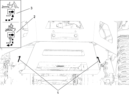
-
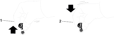
Locate the bypass levers on the frame on both sides of the engine.
-
Move both bypass levers forward through the slotted hole and over to lock them in place  .
.
|
Warning |
|
Contact with hot surfaces may cause personal injury.
Keep your hands, feet, face, clothing and other body parts away the engine, muffler and other hot surfaces.
|
Warning |
|
The machine could unintentionally move while the bypass levers are locked forward in the slot and injure you or bystanders.
Lock the bypass levers rearward after moving the machine.
-
Disengage the parking brake by moving both motion-control levers down to the center, unlocked position.
Note: Do not start the machine.
-
Move the machine as required.
Always push the machine by hand. Do not tow the machine, because towing may damage it.
-
Move the motion-control levers outward to the Park position.
-
Move both bypass levers rearward and over through the slotted hole to lock them in place  .
.
Raising the Machine
-
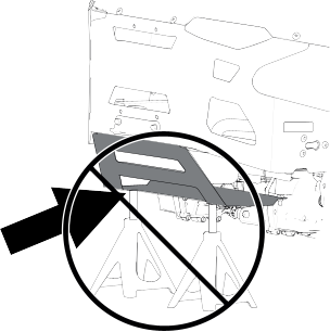
Use jackstands to support the machine when you raise it.
|
Warning |
|
Supporting the machine on the lower muffler shield may damage the shield and cause the machine to fall, injuring you or bystanders.
Do not use the lower muffler shield to lift or support the machine.
Lubrication
Greasing the Bearings
-
Park the machine on a level surface, disengage the blade-control switch, and move the motion-control levers outward to the
Park position.
-
Shut off the engine and wait for all moving parts to stop before leaving the operating position.
-
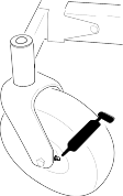
Clean the grease fittings with a rag.
Note: Scrape any paint off the front of the fittings.
-
Connect a grease gun to each fitting.
-
Pump grease into the fittings until grease begins to ooze out of the bearings.
-
Wipe up any excess grease.
Engine Maintenance
Engine Safety
- Keep your hands, feet, face, other body parts, and clothing away from the muffler and other hot surfaces. Wait for the engine
to cool before performing maintenance.
- Do not change the engine governor speed or overspeed the engine.
Air Cleaner Service
Removing the Air-Cleaner Element
-
Park the machine on a level surface, disengage the blade-control switch, and move the motion-control levers outward to the
Park position.
-
Shut off the engine and wait for all moving parts to stop before leaving the operating position.
-
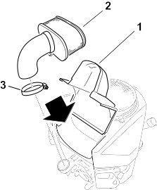
Clean around the air-cleaner cover to prevent dirt from getting into the engine and causing damage.
-
Loosen the hose clamp and remove the paper element .
Servicing the Paper Air-Cleaner Element
-
Clean the paper element by tapping it gently to remove dust.
Note: If it is very dirty, replace the paper element with a new one.
-
Inspect the element for tears, an oily film, or damage to the rubber seal.
-
Replace the paper element if it is damaged.
Do not clean the paper filter.
Engine-Oil Service
Engine-Oil Specifications
|
Oil Type
|
Detergent oil (API service SF, SG, SH, SJ, or SL)
|
|
Crankcase Capacity
|
1.8 L (61 fl oz); without filter; 2.1 L (70 fl oz) with filter
|
|
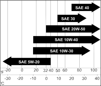
Viscosity
|
See the table below
|
|
|
Checking the Engine-Oil Level
-
Park the machine on a level surface, disengage the blade-control switch, and move the motion-control levers outward to the
Park position.
-
Shut off the engine, remove the key, and wait for all moving parts to stop before leaving the operating position.
-
Wait for the engine to cool so that the oil has had time to drain into the sump.
-
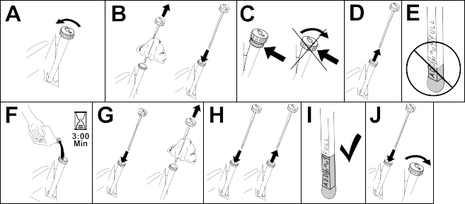
To keep dirt, grass clippings, etc., out of the engine, clean the area around the oil-fill cap and dipstick before removing
it.
-
Check the engine-oil level as shown.
If you overfill or underfill the engine crankcase with oil and run the engine, you may damage the engine.
Changing the Engine Oil
-
Park the machine so that the drain side is slightly lower than the opposite side to ensure that the oil drains completely.
-
Disengage the blade-control switch (PTO) and move the motion-control levers outward to the Park position.
-
Shut off the engine, remove the key, and wait for all moving parts to stop before leaving the operating position.
-
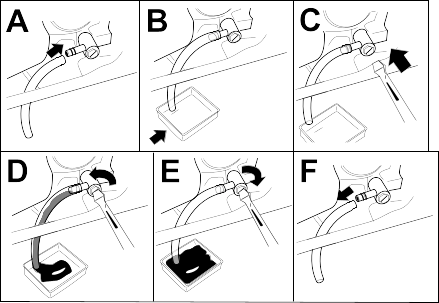
Drain the oil from the engine.
-
Slowly pour approximately 80% of the specified oil into the filler tube and slowly add the additional oil to bring it to the
Full mark.
-
Dispose of the used oil at a recycling center.
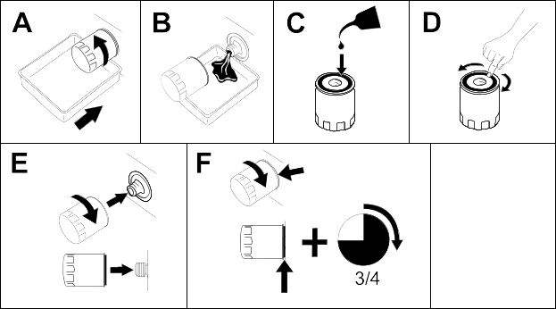
Changing the Engine-Oil Filter
-
Drain the oil from the engine.
-
Change the engine-oil filter as shown.
Note: Ensure that the oil-filter gasket touches the engine, and then turn the oil filter an extra 3/4 turn.
-
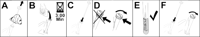
Slowly add the specified oil into the filler tube to bring the oil level to the Full mark.
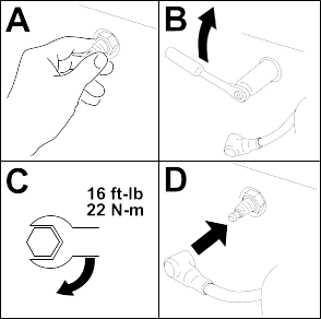
Servicing the Spark Plug
Ensure that the air gap between the center and side electrodes is correct before installing the spark plug. Use a spark plug
wrench for removing and installing the spark plug and a gapping tool or feeler gauge to check and adjust the air gap. Install
a new spark plug if necessary.
Type: NGK® BPR4ES
Air gap: 0.76 mm (0.03 inch)
Removing the Spark Plug
-
Park the machine on a level surface, disengage the blade-control switch, and move the motion-control levers outward to the
Park position.
-
Shut off the engine, remove the key, and wait for all moving parts to stop before leaving the operating position.
-
Clean the area around the base of the plug to keep dirt and debris out of the engine.
-
Remove the spark plug.
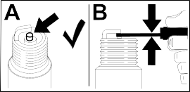
Checking the Spark Plug
Do not clean the spark plug(s). Always replace the spark plug(s) when it has a black coating, worn electrodes, an oily film,
or cracks.
If you see light brown or gray on the insulator, the engine is operating properly. A black coating on the insulator usually
means the air cleaner is dirty.
-
Set the gap to 0.75 mm (0.03 inch).
Installing the Spark Plug
Cleaning the Cooling System
-
Park the machine on a level surface, disengage the blade-control switch, and move the motion-control levers outward to the
Park position.
-
Shut off the engine, remove the key, and wait for all moving parts to stop before leaving the operating position.
-
Remove the air filter from the engine.
-
Remove the engine shroud.
-
To prevent debris entering the air intake, install the air filter to the filter base.
-
Clean debris and grass from the parts.
-
Remove the air filter and install the engine shroud.
-
Install the air filter.
Fuel Maintenance
|
Danger |
|
In certain conditions, fuel is extremely flammable and highly explosive. A fire or explosion from fuel can burn you and others
and can damage property.
Refer to Fuel Safety for a complete list of fuel related precautions.
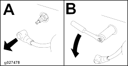
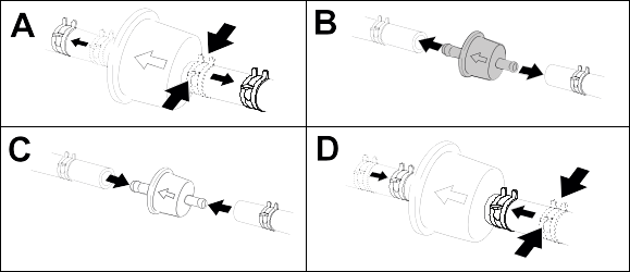
Replacing the Fuel Filter
-
Park the machine on a level surface, disengage the blade-control switch, and move the motion-control levers outward to the
Park position.
-
Shut off the engine, remove the key, and wait for all moving parts to stop before leaving the operating position.
-
Clamp the fuel lines on both sides of the fuel filter.
-
Replace the filter.
Note: Ensure that the flow-direction arrow on the replacement filter points toward the engine.
Never install a dirty filter after removing it from the fuel line.
-
Remove the clamps blocking the fuel flow.
Electrical System Maintenance
Electrical System Safety
- Disconnect the cable from the negative terminal of the battery before repairing the machine.
- Charge the battery in an open, well-ventilated area, away from sparks and flames. Unplug the charger before connecting or
disconnecting the battery. Wear protective clothing and use insulated tools.
Battery Service
Removing the Battery
|
Warning |
|
Battery terminals or metal tools could short against metal machine components, causing sparks. Sparks can cause the battery
gasses to explode, resulting in personal injury.
- When removing or installing the battery, do not allow the battery terminals to touch any metal parts of the machine.
- Do not allow metal tools to short between the battery terminals and metal parts of the machine.
-
Park the machine on a level surface, disengage the blade-control switch, and move the motion-control levers outward to the
Park position.
-
Shut off the engine, remove the key, and wait for all moving parts to stop before leaving the operating position.
-
Disconnect the negative (black) ground cable from the battery post.
Note: Retain all fasteners.
|
Warning |
|
Incorrectly removing the cables from battery could damage the machine and cables, causing sparks. Sparks can cause the battery
gasses to explode, resulting in personal injury.
- Always disconnect the negative (black) battery cable before disconnecting the positive (red) cable.
- Always connect the positive (red) battery cable before connecting the negative (black) cable.
-
Slide the rubber cover off the positive (red) cable.
-
Disconnect the positive (red) cable from the battery post (+).
Note: Retain all fasteners.
-
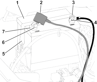
Remove the battery hold-down and lift the battery from the battery tray.
G440221
-
Battery
-
Terminal boot
-
Negative (–) battery post
-
Wing nut, washer, and bolt
-
Battery hold-down
-
Bolt, washer, and nut
-
Positive (+) battery post
Charging the Battery
|
Warning |
|
Charging the battery produces gasses that can explode.
Never smoke near the battery and keep sparks and flames away from battery.
Always keep the battery fully charged. This is especially important to prevent battery damage when the temperature is below
0°C (32°F).
-
Remove the battery from the machine.
-
Charge the battery per the battery charger manufacturer’s instructions.
Do not overcharge the battery; otherwise, you could damage it.
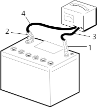
G003792S
- Positive battery post
- Negative battery post
- Red (+) charger lead
- Black (-) charger lead
-
When the battery is fully charged, unplug the charger from the electrical outlet (if applicable), then disconnect the charger
leads from the battery posts.
Cleaning the Battery
Note: Keep the terminals and the entire battery case clean, because a dirty battery discharges slowly.
-
Park the machine on a level surface, disengage the blade-control switch, and move the motion-control levers outward to the
Park position.
-
Shut off the engine and wait for all moving parts to stop before leaving the operating position.
-
Remove the battery from the machine.
-
Wash the entire case with a solution of baking soda and water.
-
Rinse the battery with clear water.
-
Coat the battery posts and cable connectors with Grafo 112X (skin-over) grease or petroleum jelly to prevent corrosion.
-
Install the battery.
Installing the Battery
-
Position the battery in the tray.
-
Using the fasteners previously removed, install the positive (red) battery cable to the positive (+) battery terminal.
-
Using the fasteners previously removed, install the negative battery cable to the negative (-) battery terminal.
-
Slide the red terminal boot onto the positive (red) battery post.
-
Secure the battery with the hold-down.
G440221
-
Battery
-
Terminal boot
-
Negative (–) battery post
-
Wing nut, washer, and bolt
-
Battery hold-down
-
Bolt, washer, and nut
-
Positive (+) battery post
Jump-Starting the Machine
|
Warning |
|
Jump-starting the battery can produce gasses that can explode.
Do not smoke near the battery, and keep sparks and flames away from battery.
|
Danger |
|
Jump-starting a weak battery that is cracked or frozen or has a low electrolyte level or an open/shorted battery cell can
cause an explosion, resulting in serious personal injury.
Do not jump-start a weak battery if these conditions exist.
-
Check and clean corrosion from the battery terminals before jump-starting. Ensure that the connections are tight.
|
Caution |
|
Corrosion or loose connections can cause unwanted electrical voltage spikes at any time during the jump-starting procedure.
Do not attempt to jump-start the machine with loose or corroded battery terminals, or damage to the engine may occur.
-
Make sure that the booster battery is a good and fully charged lead-acid battery at 12.6 V or greater.
Note: Use properly sized jumper cables with short lengths to reduce voltage drop between systems. Make sure that the cables are
color coded or labeled for the correct polarity.
|
Warning |
|
Batteries contain acid and produce explosive gases.
- Shield your eyes and face from the batteries at all times.
- Do not lean over the batteries.
Note: Ensure that the vent caps are tight and level. Place a damp cloth, if available, over any vent caps on both batteries. Also
ensure that the machines do not touch and that both electrical systems are off and at the same rated system voltage. These
instructions are for negative ground systems only.
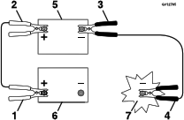
-
Connect the positive (+) cable to the positive (+) terminal of the discharged battery that is wired to the starter or solenoid
as shown:
g012785
- Positive (+) cable on discharged battery
- Positive (+) cable on booster battery
- Negative (–) cable on the booster battery
- Negative (–) cable on the engine block
- Booster battery
- Discharged battery
- Engine block
-
Connect the other end of the positive (+) jumper cable to the positive terminal of the battery in the other machine.
-
Connect an end of the negative (-) jumper cable to the negative post of the battery in the other machine.
-
Connect the other end of the negative (-) jumper cable to a ground point, such as an unpainted bolt or chassis member.
-
Start the engine in the other machine. Let it run a few minutes, then start your engine.
-
Remove the cables in the reverse order of connection.
-
Install the cover to the jump post.
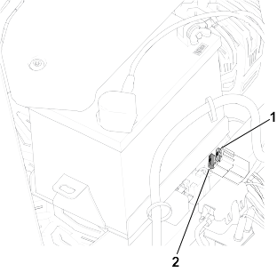
Servicing the Fuses
The electrical system is protected by fuses. It requires no maintenance; however, if a fuse blows, check the component/circuit
for a malfunction or short.
-
Park the machine on a level surface, disengage the blade-control switch, and move the motion-control levers outward to the
Park position.
-
Shut off the engine, remove the key, and wait for all moving parts to stop before leaving the operating position.
-
Replace the blown fuse with a new fuse.
G440132
- Charge circuit (15 A)
- Main (25 A)
Drive System Maintenance
Checking the Tire Pressure
Maintain the air pressure in the front and rear tires as specified. Uneven tire pressure can cause an uneven cut. Check the
pressure at the valve stem when the tires are cold to get the most accurate pressure reading.
-
Inflate the front caster wheel tires to 206 kPa (30 psi) or the pressure indicated on the sidewall, whichever is lower.
-
Inflate the rear drive-wheel tires to 90 kPa (13 psi).
Checking the Wheel Lug Nuts
-
Check and torque the wheel lug nuts to 108 N∙m (80 ft-lb).
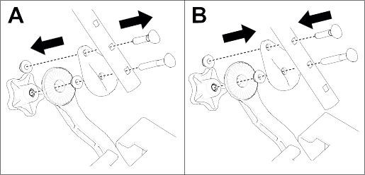
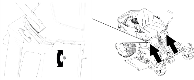
Adjusting the Tracking
When driving the machine forward full speed across a flat, level surface, if the machine pulls to 1 side, adjust the tracking.
If the machine pulls to the left, adjust the right motion-control lever; if the machine pulls to the right, adjust the left
motion-control lever.
Note: You can adjust the tracking only for driving forward.
-
Park the machine on a level surface, disengage the blade-control switch, and move the motion-control levers outward to the
Park position.
-
Shut off the engine, remove the key, and wait for all moving parts to stop before leaving the operating position.
-
Locate the tracking-adjustment bolt near the motion-control lever on the particular side that needs adjusting.
-
Rotate the bolt to decrease the speed for that particular wheel.
Note: Rotate the bolt a small amount to make minor adjustments.
-
Start the machine and drive forward across a flat, level surface with the motion-control levers fully forward to check if
the machine tracks straight. Repeat the procedure as needed.
Belt Maintenance
Inspecting the Belts
-
Park the machine on a level surface, disengage the blade-control switch, and move the motion-control levers outward to the
Park position.
-
Shut off the engine and wait for all moving parts to stop before leaving the operating position.
-
Set the height of cut at the lowest cutting position.
-
Inspect the belt for wear. Replace the belt if it is worn.
The signs of a worn belt include squealing while the belt is rotating; the blades slipping while cutting grass; and frayed
edges, burn marks, and cracks on the belt.
Replacing the Mower Belt
The signs of a worn belt include squealing while the belt is rotating, blades slipping while cutting grass, and frayed edges,
burn marks, and cracks on the belt. Replace the mower belt if any of these conditions are evident.
-
Park the machine on a level surface, disengage the blade-control switch, and move the motion-control levers outward to the
Park position.
-
Shut off the engine, remove the key, and wait for all moving parts to stop before leaving the operating position.
-
Set the height of cut at the lowest cutting position.
-
Remove the pulley covers as follows:
- For 50-inch or 54-inch decks, remove the hairpin cotter and push in the tab on the cover.
- For 60-inch decks, pull up the side of the cover with the grommet and slide the cover off.
-
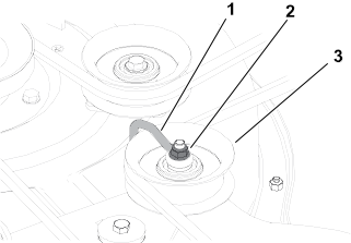
For 50-inch or 54-inch decks, loosen the nut securing the wire form to the idler pulley.
G336421s
- Wire form
- Nut
- Idler pulley
-
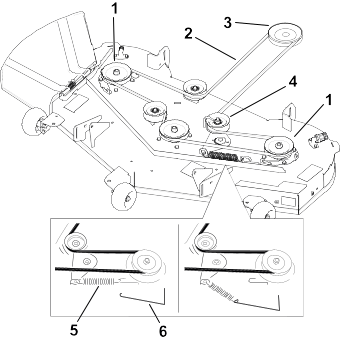
Using a spring-removal too (Toro Part No. 92-5771), remove the idler spring from the deck hook to remove tension on the idler
pulley.
|
Warning |
|
The spring is under tension when installed and can cause personal injury.
Be careful when removing the belt.
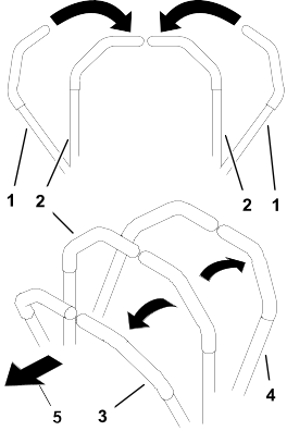
G454314
- Deck pulley
- Mower belt
- Engine pulley
- Idler pulley
- Spring
- Spring-removal tool
-
Roll the belt off the pulleys.
-
Route the new belt around the engine pulley and mower pulleys.
-
Use the spring-removal tool to install the idler spring over the deck hook and place tension on the idler pulley and the mower
belt.
-
Tighten the nut securing the wire form to the idler pulley.
Note: Position the wire form against the idler arm.
-
Install the pulley covers.
Mower-Deck Maintenance
Blade Safety
- Inspect the blades periodically for wear or damage.
- Use care when checking the blades. Wrap the blade(s) or wear gloves and use caution when servicing them. Only replace damaged
blades; never straighten or weld them.
- On multi-bladed machines, take care as rotating one blade can cause other blades to rotate.
- Replace worn or damaged blades and bolts in sets to preserve balance.
Blade Service
To ensure a superior quality of cut, keep the blades sharp. For convenient sharpening and replacement, keep extra blades on
hand.
Replace the blades if they hit a solid object, or if the blade is out of balance or bent.
Before Inspecting or Servicing the Blades
-
Park the machine on a level surface, disengage the blade-control switch, and move the motion-control levers outward to the
Park position.
-
Shut off the engine, remove the key, and wait for all moving parts to stop before leaving the operating position.
-
Disconnect the spark-plug wires from the spark plugs.
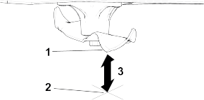
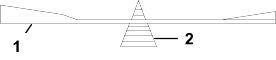
Checking for Bent Blades
The machine must be on a level surface for this procedure.
-
Raise the mower deck to the highest height-of-cut position.
-
While wearing thickly padded gloves, or other adequate hand protection, slowly rotate the blade into a position that allows
you to measure the distance between the cutting edge and the level surface.
-
Measure from the tip of the blade to the level surface.
G451422
- Blade (in position for measuring)
- Level surface
- Measured distance between blade and the surface (A)
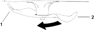
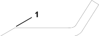
-
Rotate the same blade 180 degrees so that the opposite blade edge is now in the same position.
G451423
- Blade edge previous measured
- Opposite blade edge
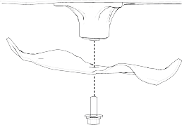
-
Measure from the tip of the blade to the level surface.
G451422
- Blade (in position for measuring)
- Level surface
- Measured distance between blade and the surface (B)
-
If the difference between A and B is greater than 3 mm (1/8 inch), replace the blade.
Note: If you replace the blade and the difference continues to exceed 3 mm (1/8 inch), the blade spindle could be bent. Contact
an Authorized Service Dealer for service.
-
Repeat this procedure each blade.
Removing the Blades
-
Hold the blade end using a rag or thickly padded glove.
-
Remove the blade as shown.
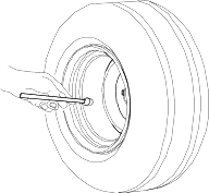
Sharpening the Blades
-
Use a file to sharpen the cutting edge at both ends of the blade. Ensure to maintain the original angle .
Note: Remove the same amount of material from both cutting edges so that the blade retains its balance.
-
Check the balance of the blade by putting it on a blade balancer .
Note: If the blade stays in a horizontal position, the blade is balanced and can be used.
If the blade is not balanced, file some metal off the end of the sail area only.
-
Repeat this procedure until the blade is balanced.
Installing the Blades
|
Warning |
|
Operating a machine after incorrectly installing the blade assembly and/or not using genuine Toro blade and blade hardware could allow a blade or blade component to be thrown out from under the deck, resulting in serious
injury or death.
Always install genuine Toro blades and blade hardware according to the instructions.
-
Install the blade as shown.
Note: The curved part of the blade must be pointing upward toward the inside of the mower to ensure proper cutting.
-
Torque the blade bolt to 81 to 108 N·m (60 to 80 ft-lb).
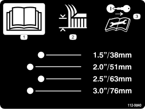
Leveling the Mower Deck
Ensure that the mower deck is level any time you install the mower deck or when you see an uneven cut on your lawn.
Preparing to Level the Mower Deck
-
Park the machine on a level surface, disengage the blade-control switch, and move the motion-control levers outward to the
Park position.
-
Shut off the engine, remove the key, and wait for all moving parts to stop before leaving the operating position.
-
Ensure that the tires are inflated to the correct specifications and the caster wheels are facing straight forward.
-
Check the mower deck for bent blades; remove and replace any bent blades.
-
Raise the mower deck to the 76 mm (3 inch) height-of-cut setting.
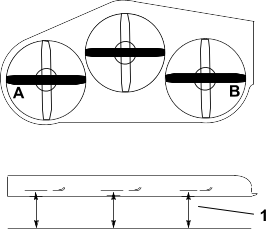
Checking the Mower-Deck Level
-
Position the blades side-to-side.
-
Measure at locations  and
and  from a level surface to the cutting edge of the blade tips .
The difference between the measurements should be no more than 5 mm (3/16 inch). If the measurement is larger, adjust the
side-to-side level.
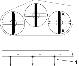
-
Position 1 blade front-to-rear.
-
Measure at locations and from a level surface to the cutting edge of the blade tips .
The front blade tip should be 1.6 to 7.9 mm (1/16 to 5/16 inch) lower than the rear blade tip. If the measurement is not correct,
adjust the front-to-rear level.
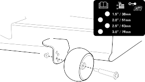
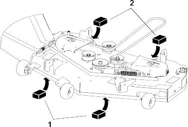
Leveling the Mower Deck
-
Set the anti-scalp rollers to the top holes or remove them completely for this procedure.
-
Set the height-of-cut lever to the 76 mm (3 inch) position.
-
Place 2 blocks , each having a thickness of 6.6 cm (2-5/8 inches), under each side of the front edge of the deck.
Do not place the blocks under the anti-scalp roller brackets.
-
Place 2 blocks , each having a thickness of 7.3 cm (2-7/8 inches), under each side of the rear edge of the deck.
-
Loosen the fasteners connecting the chains on all 4 corners of the deck and ensure that the mower deck sits securely on all
4 blocks.
-
Remove any slack from the deck chains and ensure that the deck-lift foot lever is pushed back against the stop.
-
Tighten the fasteners.
-
Ensure that the blocks fit snugly under the deck edge and that all attachment bolts are tight.
-
Check the side-to-side level and front-to-rear level; repeat the procedure until the measurements are correct.
Removing the Mower Deck
-
Park the machine on a level surface, disengage the blade-control switch, and move the motion-control levers outward to the
Park position.
-
Shut off the engine, remove the key, and wait for all moving parts to stop before leaving the operating position.
-
Lower the height-of-cut lever to the lowest position.
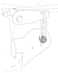
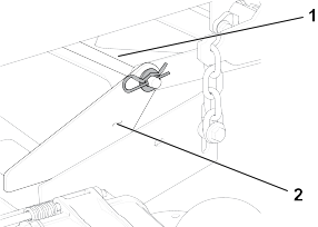
-
Remove the hairpin cotter and washer from the front support rod , and remove the rod from the deck bracket .
Note: Retain all parts for future installation.
-
Lift the deck and chains off the brackets at all 4 corners of the deck.
-
Slide the mower deck rearward to remove the mower belt from the engine pulley.
-
Slide the mower deck out from underneath the machine.
Installing the Mower Deck
-
Park the machine on a level surface, disengage the blade-control switch, and move the motion-control levers outward to the
Park position.
-
Shut off the engine, remove the key, and wait for all moving parts to stop before leaving the operating position.
-
Slide the mower deck under the machine.
-
Lower the height-of-cut lever to the lowest position.
-
Lift the mower deck chains onto the deck-lift brackets.
-
Attach the front support rod to the deck bracket with the hairpin cotter and washer.
-
Install the mower belt onto the engine pulley.
Replacing the Grass Deflector
|
Danger |
|
An uncovered discharge opening allows objects to be thrown toward you or bystanders. Also, contact with the blade could occur.
Thrown objects or blade contact will cause serious injury or death.
Do not operate the mower with the discharge deflector raised, removed, or altered unless a grass collection system or mulch
kit is in place and working properly.
-
Park the machine on a level surface, disengage the blade-control switch, and move the motion-control levers outward to the
Park position.
-
Shut off the engine, remove the key, and wait for all moving parts to stop before leaving the operating position.
-
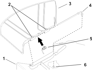
Remove the nut from the rod under the mower deck.
G451625
- Mower deck
- Grass-deflector pivot
- Grass deflector
- Rod
- Spring
- Nut
-
Slide the rod out.
-
Remove the damaged or worn grass deflector.
-
Install the new grass deflector.
-
Slide the straight end of the rod through the rear grass deflector pivot.
-
Place the spring on the rod, with end wires down, and between the grass deflector brackets.
-
Slide the rod through the second grass-deflector pivot.
-
Insert the rod at the front of the grass deflector into the bracket on the deck.
-
Secure the rear end of the rod into the mower with the nut.
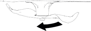
The grass deflector must be spring-loaded in the down position. Lift the deflector up to test that it snaps into the full-down
position.
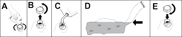
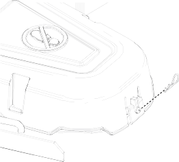
Cleaning
Washing the Underside of the Mower Deck
You can wash the machine with a mild detergent and water. Do not pressure wash the machine. Avoid excessive use of water,
especially near the control panel, under the seat, around the engine, hydraulic pumps, and motors.
Wash the underside of the mower deck after each use to prevent grass buildup for improved mulch action and clipping dispersal.
-
Park the machine on a level surface, disengage the blade-control switch (PTO), and move the motion-control levers outward
to the Park position.
-
Shut off the engine, remove the key, and wait for all moving parts to stop before leaving the operating position.
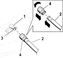
-
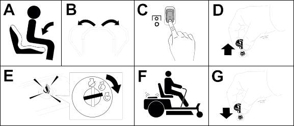
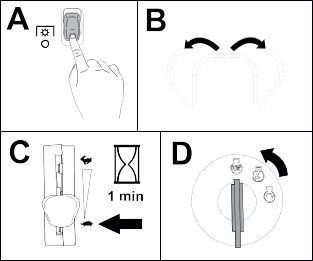
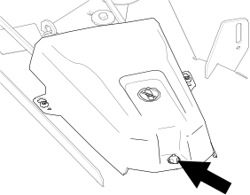
Attach a hose to the hose coupling  , then attach the hose coupling to the end of the mower washout fitting and turn the water on high.
Note: Spread petroleum jelly on the washout fitting O-ring to make the coupling slide on easier and protect the O-ring.
-
Sit on the seat, lower the mower to the lowest height-of-cut, and start the engine.
-
Engage the blade-control switch and let the mower run for 1 to 3 minutes.
-
Disengage the blade-control switch, shut off the engine, remove the key, and wait for all moving parts to stop.
-
Turn the water off and remove the coupling from the washout fitting.
Note: If the mower is not clean after 1 washing, soak it and let it stand for 30 minutes. Then repeat the process.
-
Run the mower again for 1 to 3 minutes to remove excess water.
|
Warning |
|
A broken or missing washout fitting could expose you and others to thrown objects or blade contact. Contact with a blade or
thrown debris can cause injury or death.
- Replace broken or missing washout fitting immediately, before using machine again.
- Never put your hands or feet under the mower or through openings in the machine.
Disposing of Waste
Engine oil, batteries, hydraulic fluid, and engine coolant are pollutants to the environment. Dispose of these according to
your state and local regulations.
The fuel tank is showing signs of collapsing or the machine is frequently showing signs of running out of fuel.
|
Possible Cause
|
Corrective Action
|
|
The air-cleaner paper element clogged.
|
-
Clean the paper element.
|
The engine overheats.
|
Possible Cause
|
Corrective Action
|
|
The engine load is excessive.
|
-
Reduce the ground speed.
|
|
The oil level in the crankcase is low.
|
-
Add oil to the crankcase.
|
|
The cooling fins and air passages under the engine-blower housing are plugged.
|
-
Remove the obstruction from the cooling fins and air passages.
|
|
The air cleaner is dirty.
|
-
Clean or replace the air-cleaner element.
|
|
Dirt, water, or stale fuel is in the fuel system.
|
-
Contact an Authorized Service Dealer.
|
The starter does not crank.
|
Possible Cause
|
Corrective Action
|
|
The blade-control switch is engaged.
|
-
Disengage the blade-control switch.
|
|
The motion-control levers are not in the park position.
|
-
Move the motion-control levers outward to the park position.
|
|
The battery is dead.
|
-
Charge the battery.
|
|
The electrical connections are corroded or loose.
|
-
Check the electrical connections for good contact.
|
|
A fuse is blown.
|
-
Replace the fuse.
|
|
A relay or switch is damaged.
|
-
Contact an Authorized Service Dealer.
|
The engine does not start, starts hard, or fails to keep running.
|
Possible Cause
|
Corrective Action
|
|
The fuel tank is empty.
|
-
Fill the fuel tank.
|
|
The choke (if applicable) is not on.
|
-
Move the choke lever to the on position.
|
|
The air cleaner is dirty.
|
-
Clean or replace the air-cleaner element.
|
|
The spark-plug wire(s) is loose or disconnected.
|
-
Install the wire(s) on the spark plug.
|
|
The spark plug(s) is pitted, fouled, or the gap is incorrect.
|
-
Install a new, correctly gapped spark plug(s).
|
|
There is dirt in fuel filter.
|
-
Replace the fuel filter.
|
|
Dirt, water, or stale fuel is in fuel system.
|
-
Contact an Authorized Service Dealer.
|
|
There is incorrect fuel in the fuel tank.
|
-
Drain the tank and replace the fuel with the proper type.
|
|
The oil level in the crankcase is low.
|
-
Add oil to the crankcase.
|
The engine loses power.
|
Possible Cause
|
Corrective Action
|
|
The engine load is excessive.
|
-
Reduce the ground speed.
|
|
The air cleaner is dirty.
|
-
Clean the air-cleaner element.
|
|
The oil level in the crankcase is low.
|
-
Add oil to the crankcase.
|
|
The cooling fins and air passages under the engine blower housing are plugged.
|
-
Remove the obstruction from the cooling fins and air passages.
|
|
The spark plug(s) is pitted, fouled, or the gap is incorrect.
|
-
Install a new, correctly gapped spark plug(s).
|
|
The fuel-tank vent is blocked.
|
-
Contact an Authorized Service Dealer.
|
|
There is dirt in the fuel filter.
|
-
Replace the fuel filter.
|
|
Dirt, water, or stale fuel is in the fuel system.
|
-
Contact an Authorized Service Dealer.
|
|
There is incorrect fuel in the fuel tank.
|
-
Contact an Authorized Service Dealer.
|
The machine does not drive.
|
Possible Cause
|
Corrective Action
|
|
The bypass valves are open.
|
-
Close the tow valves.
|
|
The traction belts are worn, loose, or broken.
|
-
Contact an Authorized Service Dealer.
|
|
The traction belts are off the pulleys.
|
-
Contact an Authorized Service Dealer.
|
|
The transmission has failed.
|
-
Contact an Authorized Service Dealer.
|
The machine vibrates abnormally.
|
Possible Cause
|
Corrective Action
|
|
The cutting blade(s) is/are bent or unbalanced.
|
-
Install new cutting blade(s).
|
|
The blade mounting bolt is loose.
|
-
Tighten the blade mounting bolt.
|
|
The engine mounting bolts are loose.
|
-
Tighten the engine mounting bolts.
|
|
The engine pulley, idler pulley, or blade pulley is loose.
|
-
Tighten the appropriate pulley.
|
|
The engine pulley is damaged.
|
-
Contact an Authorized Service Dealer.
|
|
The blade spindle is bent.
|
-
Contact an Authorized Service Dealer.
|
|
The motor mount is loose or worn.
|
-
Contact an Authorized Service Dealer.
|
The cutting height is uneven.
|
Possible Cause
|
Corrective Action
|
|
The blade(s) is not sharp.
|
-
Sharpen the blade(s).
|
|
A cutting blade(s) is/are bent.
|
-
Install a new cutting blade(s).
|
|
The mower is not level.
|
-
Level the mower from side-to-side and front-to-rear.
|
|
An anti-scalp roller (if applicable) is not set correctly.
|
-
Adjust the anti-scalp wheel height.
|
|
The underside of the mower deck is dirty.
|
-
Clean the underside of the mower deck.
|
|
The tire pressure is incorrect.
|
-
Adjust the tire pressure.
|
|
A blade spindle is bent.
|
-
Contact an Authorized Service Dealer.
|
The blades do not rotate.
|
Possible Cause
|
Corrective Action
|
|
The drive belt is worn, loose or broken.
|
-
Install a new drive belt.
|
|
The drive belt is off of the pulley.
|
-
Install the drive belt and check the adjusting shafts and belt guides for the correct position.
|
|
The power-takeoff (PTO) switch or PTO clutch is faulty.
|
-
Contact an Authorized Service Dealer.
|
|
The mower belt is worn, loose, or broken.
|
-
Install a new mower belt.
|