Introduction
Read this manual carefully to learn how to operate and maintain your product properly. The information in this manual can help you and others avoid injury and product damage. Although Toro designs and produces safe products, you are responsible for operating the product properly and safely.
You may contact Toro directly at www.Toro.com for product safety and operation training materials, accessory information, help finding a dealer, or to register your product.
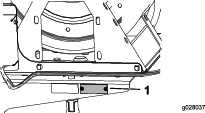
Whenever you need service, genuine Toro parts, or additional information, contact an Authorized Service Dealer or Toro Customer Service and have the model and serial numbers of your product ready. Figure 1 illustrates the location of the model and serial numbers on the product.
Note: This product complies with all relevant European directives. For details, please see the Declaration of Incorporation (DOI) at the back of this publication.Determine the left and right sides of the machine from the normal operating position.
Warning
CALIFORNIA
Proposition 65 Warning
Use of this product may cause exposure to chemicals known to the State of California to cause cancer, birth defects, or other reproductive harm.
Safety
Improper use or maintenance by the operator or owner can result in injury. To reduce the potential for injury, comply with these safety instructions and always pay attention to the safety-alert symbol, which means Caution, Warning, or Danger—personal safety instruction. Failure to comply with the instruction may result in personal injury or death.
Read also the safety and operation instructions in the vehicle Operator's Manual.
-
Do not aim the hand sprayer at any person or animal. Fluids under high pressure can penetrate skin and cause severe injury, possibly resulting in amputation or death. Hot liquids and chemicals can also cause burns or injury. If any part of the body comes in contact with the spray stream, immediately consult a physician familiar with injected fluid injuries.
-
Do not place your hand or any other part of your body in front of the spray nozzle.
-
Do not leave the equipment under pressure when you are not present.
-
Do not use the hand sprayer if the hose, trigger lock, nozzle, or any other part is damaged or missing.
-
Do not use the hand sprayer if there are any leaks in any hoses, fittings, or other components.
-
Do not spray near power lines.
-
Do not drive while spraying with a hand sprayer.
-
Wear rubber gloves, safety goggles, and a full-body protective suit when spraying chemicals with the hand sprayer.
-
Lightning can cause severe injury or death. If lightning is seen or thunder is heard in the area, do not operate the machine; seek shelter.
Caution
Chemicals are hazardous and can cause personal injury.
-
Read the directions on the chemical labels before handling the chemicals and follow all manufacturer recommendations and precautions.
-
Keep chemicals away from your skin. Should contact occur, wash the affected area thoroughly with soap and clean water.
-
Wear goggles and any other protective equipment recommended by the chemical manufacturer.
Safety and Instructional Decals
 |
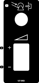
Safety decals and instructions are easily visible to the operator and are located near any area of potential danger. Replace any decal that is damaged or missing. |
Setup
Customer provided supplies:
-
PTFE thread sealant (tape or paste)
-
A non-petroleum-based lubricant such as vegetable oil
Preparing the Machine
Warning
Battery terminals or metal tools could short against metal machine components, causing sparks. Sparks can cause the battery gasses to explode, resulting in personal injury.
-
When removing or installing the battery, do not allow the battery terminals to touch any metal parts of the tractor.
-
Do not allow metal tools to short between the battery terminals and metal parts of the machine.
Warning
Incorrect battery cable routing could damage the machine and cables, causing sparks. Sparks can cause the battery gasses to explode, resulting in personal injury.
-
Always disconnect the negative (black) battery cable before disconnecting the positive (red) cable.
-
Always connect the positive (red) battery cable before connecting the negative (black) cable.
-
If the optional rinse tank is installed, empty the tank into the spray tank; refer to Operating the Rinse Kit in the Installation Instruction for the Tank Rinse Kit.
-
Ensure that the sprayer tank of the machine is empty of all fluids.
Note: If the sprayer tank has contained chemical solutions, flush the tank and sprayer system thoroughly with clean water; refer to your vehicle Operator's Manual for instructions.
-
Park the machine on a level surface, set the parking brake, shut off the sprayer pump, shut off the engine, and remove the key from the key switch.
-
Disconnect the negative battery cable from the negative post of the battery; refer to the Operator’s Manual.
-
Disconnect the positive battery cable from the positive post of the battery; refer to the Operator’s Manual.
Removing the Rinse Tank and Moving the Spray Tank
Removing the Rinse Tank
-
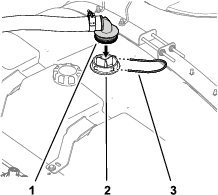
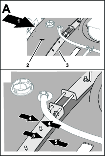
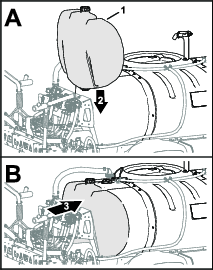
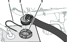
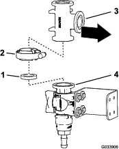
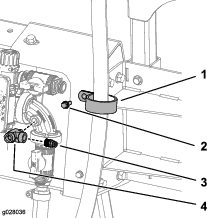
At the top of the spray tank, remove the retainer fork that secures the 90° barbed fitting of the suction hose to the housing for the suction screen, and separate the barbed fitting from the housing (Figure 2).
-
Remove the 90° fitting from the suction-screen housing (Figure 2).
-
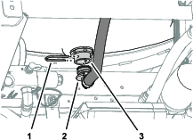
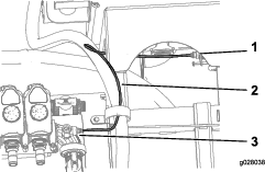
At the bottom of the rinse tank, remove the retainer fork that secures the 90° fitting of the supply hose to the bulkhead fitting (Figure 3).
-
Remove the 90° fitting from the bulkhead fitting (Figure 3).
-
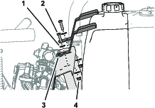
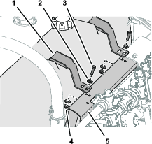
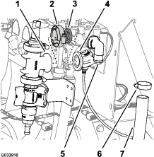
Remove the 2 bolts, 4 washers, and 2 flange locknuts that secure the 2 hold-down brackets for the rinse tank to the valve mount, and remove the hold-down brackets (Figure 4).
-
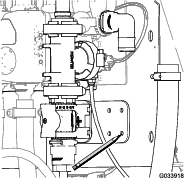
Remove the rinse tank from the machine (Figure 5).
Moving the Spray Tank
-
Loosen the 4 flange locknuts and 4 bolts that secure the tank-strap halves (Figure 7).
-
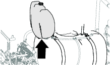
Move the spray tank forward until the straps are aligns flush with the rearmost shoulder of the strap relief molded into the tank (Figure 8).
-
Tighten the 4 flanged locknuts and 4 bolts at the top of straps until the straps are flush with the surface of the tank (Figure 7).
Installing the Hose-Reel Frame
Parts needed for this procedure:
| Nut (1/4-20 inch) | 1 |
| Flange nut (5/16-18 inch) | 5 |
| Flange nut (3/8-16 inch) | 12 |
| Bolt (3/8-16 x 1 inch) | 5 |
| Bolt (1/4-20 x 3/4 inch) | 1 |
| Bolt (3/8-16 inch) | 2 |
| Bolt (3/8-16 x 3 1/2 inch) | 2 |
| Upper bracket | 1 |
| Lower-bracket support | 1 |
| Lower bracket | 1 |
| Whiz bolt (5/16-18 x 1 inch) | 1 |
| U-Bolt | 1 |
| Bolt (3/8-16 x 2 1/4 inch) | 2 |
| Reel-shelf support bracket | 1 |
| Shoulder bolt | 4 |
| Reel shelf frame | 1 |
| Jam nut (5/16-18 inch) | 2 |
| Bolt (5/16-18 x 1 inch) | 2 |
| Pressure gauge reducer | 1 |
| Coupler | 1 |
| Pressure gauge | 1 |
-
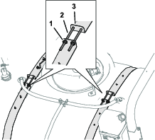
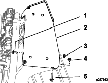
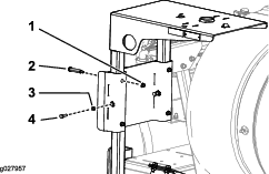
Mount the upper bracket using 1 bolt (1/4-20 x 3/4 inch), 1 nut (1/4-20 inch), 1 whiz bolt (5/16-18 x 1 inch), and 1 flange nut (5/16-18 inch) as shown in Figure 9.
-
Secure the back side of the upper bracket using 1 U-bolt, 1 bolt (3/8-16 x 1 inch), and 3 flange nuts (3/8-16 inch) as shown in Figure 10.
Note: If a rinse tank was removed before installing the upper bracket, install the rinse tank before proceeding to the next step.
-
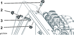
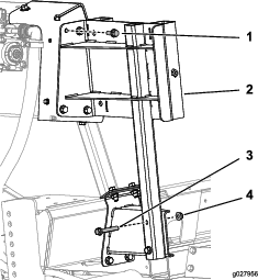
Mount the lower bracket and lower support bracket to the frame using 2 bolts (3/8-16 inch), 2 bolts (3/8-16 x 3 1/2 inch), and 4 flange nuts (3/8-16 inch) as shown in Figure 11.
-
If your machine has the optional rinse tank kit installed, align the tank to the machine as shown in figure (Figure 12).
Note: You will complete the rinse tank installation in Installing the Rinse Tank.
-
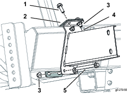
Secure the reel-shelf support bracket to the upper and lower brackets using 4 bolts (3/8-16 x 1 inch), 2 bolts (3/8-16 x 2 1/4 inch), and 6 flange nuts (3/8-16 inch) as shown in Figure 13.
-
Insert the reel shelf frame into the slots onto the reel-shelf support bracket and secure the shelf using 4 shoulder bolts, 4 flange nuts (5/16-18 inch), 2 bolts (5/16-18 x 1 inch), and 2 jam nuts (5/16-18 inch) as shown in Figure 14.
-
Apply PTFE tape to the threads on the pressure gauge and install the pressure gauge assembly as shown in Figure 15.
-
Tighten the bolts on the pressure-gauge support bracket against the reel-shelf frame.
Assembling the Optional Rinse Tank
Installing the Rinse Tank
-
Align the hold-down bracket with the reliefs molded into the top of the rinse tank (Figure 16)
-
Align the slot in the hold-down bracket with the hole in the valve mount (Figure 16).
-
Loosely assemble the hold down to the valve mount (Figure 16) with a bolt (3/8 x 1-1/2 inches), 2 washers (3/8 inch), and a flange locknut (3/8 inch) that you removed in Removing the Rinse Tank.
-
Repeat steps 1 through 3 for the other hold down at the other recess in the rinse tank (Figure 16).
-
Carefully tighten the bolts and flange nuts by hand.
Important: The rinse tank must be seated and secure, but the hold down should not deform or warp the tank
Note: Once the rinse tank has been initially filled, check the hold downs and the rinse tank for play (the weight of the water in the tank can further seat the tank against the frame). If needed, tighten the bolt(s) and flange locknut(s) until the hold downs are snug against the rinse tank—do not deform the tank.
Installing the Spray Tank Suction Hose
Assembling the Supply Hose
-
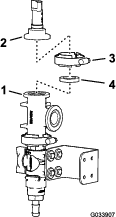
Align the 90° barbed fitting of the supply hose with the housing for the suction screen (Figure 18).
-
Secure the 90° barbed fitting to the housing (Figure 18) with the retainer fork that you removed in step 1 of Removing the Rinse Tank.
Installing the Switch Box and Hose Reel
Parts needed for this procedure:
| Wiring harness | 1 |
| Switch box assembly | 1 |
| Thrust washer | 1 |
| Snap ring | 1 |
| Hose reel assembly | 1 |
| Spring pin | 1 |
| Washer (7/16 inch) | 4 |
| Flange nut (5/16-18 inch) | 2 |
| Bolt (5/16-18 x 1/4 inch) | 2 |
| Washer | 1 |
| Flange nut (3/8-16 inch) | 4 |
| Bolt (3/8-16 x 1 inch) | 4 |
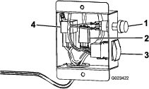
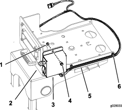
Note: The fuse for the hose-reel motor is located in the switch box (Figure 19).
-
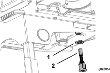
Drop the swivel plate into the hole on the hose-reel base.
-
On the underside of the hose-reel frame, attach the thrust washer and snap ring to the post on the swivel plate (Figure 20).
-
Mount the switch box to the swivel plate using 2 bolts (5/16-18 x 1/4 inch) and 2 flange nuts (5/16-18 inch) as shown in Figure 21.
-
Secure the wiring harness to the sides of the swivel plate using the existing clips (Figure 21).
-
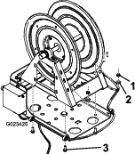
Secure the hose reel to the swivel plate using 4 bolts (3/8-16 x 1 inch), 4 washers (7/16 inch), and 4 flange nuts (3/8-16 inch) as shown in Figure 22.
Note: The hose-reel motor should face away from the switch panel.
-
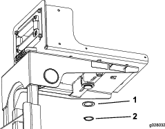
Install the washer and spring pin to the underside of the hose-reel frame (Figure 23).
-
Connect the remaining wiring harness plugs to the motor, the main harness power, and the hose reel kit plugs.
Installing the Control Valve for the Hose Reel
Parts needed for this procedure:
| Control valve | 1 |
| T-fitting | 1 |
| Hose clamp | 1 |
| Cable tie | 3 |
| R-clamp | 1 |
| Hose (71 inches) | 1 |
| Clamp | 1 |
| 90° elbow | 1 |
| Tube coupler | 1 |
| Nut (1/4-20 inch) | 1 |
| Flange nut (3/8-16 inch) | 1 |
| Pressure transducer tube | 1 |
| Bolt (1/4-20 x 3/4 inch) | 1 |
| Valve mount | 1 |
| Control-valve bracket | 1 |
| Bolt (6 x 12 mm) | 4 |
| Washer (8 mm) | 4 |
| Flange head bolt (6 x 16 mm) | 4 |
| Flange locknut (6 mm) | 4 |
Assembling the Control Valve
-
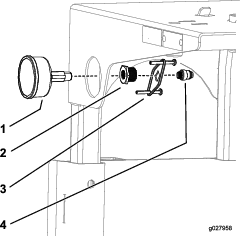
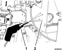
Disconnect the cap and coupler from the pressure-gauge port (Figure 24).
-
Install the control valve assembly as shown in Figure 24.
-
Install the coupler into the open port on the 90° elbow (Figure 24 and Figure 37).
Note: The cap can be discarded.
-
Connect the hose-reel supply hose to the control valve using a hose clamp (Figure 24).
Removing the Control Valve from the Machine
-
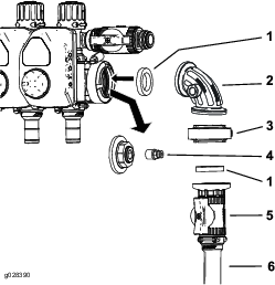
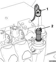
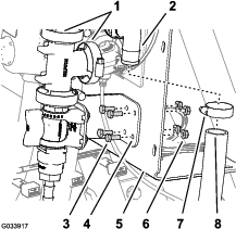
Disconnect the 3-socket connector for the pressure transducer (Figure 25).
-
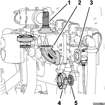
Remove the flange clamp that secures the pressure transducer to the 90° fitting, and remove the transducer, gasket and flange clamp (Figure 26).
-
Remove the flange clamp that secures 90° fitting to the 90° fitting with a connector for the sense tube, and remove the 90° fitting, gasket and flange clamp (Figure 26)
Preparing the Control Valve
-
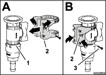
Assemble the valve mount onto the control valve as shown in A of Figure 27.
-
Secure the valve mount to the control valve with the flange-head screw (#6), and tighten the screw by hand (B of Figure 27).
-
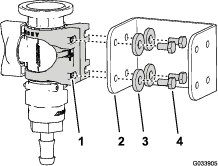
Assemble the valve mount to the control-valve bracket (Figure 28) with the 4 bolts (6 x 12 mm) and 4 flat washers; torque the bolts to 10 to 12 N∙m (86 to 106 in-lb).
-
Align the flange of the T-fitting to the flange of the control valve as shown in Figure 29.
-
Loosely attach the T-fitting to the control valve with a gasket and flange clamp (Figure 29).
-
Align the flange of the pressure transducer with the flange of the T-fitting as shown in Figure 30.
-
Assemble the pressure transducer to the T-fitting with a gasket and flange clamp, and tighten the clamp by hand (Figure 30).
Drilling the Manifold Mount
-
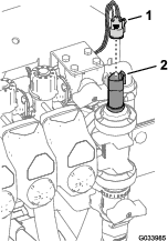
Align the flange of the T-fitting with the flange of the 90° fitting with a connector for the sense tube (Figure 31).
-
Loosely assemble the T-fitting and the 90° fitting with a gasket and a flange clamp (Figure 31)
Note: Rotate the control-valve bracket as necessary to align it flush with the surface of the valve mount.
-
Using the control-valve bracket as a template, mark the location of the holes in the bracket onto the surface of the manifold mount (Figure 32).
-
Remove the clamp, gasket, T-fitting with the flange from the 90° fitting with a connector for the sense tube (Figure 31).
-
Center punch the marks on the manifold mount that you made in step 3.
-
Drill 4 holes 6 mm (1/4 inch) into the manifold mount at the centerpunch marks that you made in step 5.
Assembling the Control Valve
-
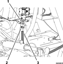
Align the flange of the T-fitting with the flange of the 90° fitting with a connector for the sense tube (Figure 34).
-
Loosely assemble the T-fitting and the 90° fitting with a gasket and a flange clamp (Figure 34).
-
Assemble the control-valve bracket to the manifold mount (Figure 35) with 4 flange head bolts (6 x 16 mm) and 4 flange locknuts (6 mm); torque the bolts to 10 to 12 N∙m (86 to 106 in-lb).
-
Tighten by hand the flange clamp that secures the control valve and the T-fitting (Figure 29) and the flange clamp that secures T-fitting to the 90° fitting with a connector for the sense tube (Figure 31 and Figure 34).
-
Connect the 3-socket connector for the pressure transducer (Figure 35).
-
Assemble the spray-wand hose onto the barbed-hose fitting of the control valve, and secure the hose to the fitting with a hose clamp (Figure 36).
Assembling the Supply Hose and Pressure-Sense Tube to the Machine
-
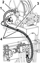
Secure the hose 180 cm (71 inches) to the upper bracket using a R-clamp, bolt (1/4-20 x 3/4 inch), and nut (1/4-20 inch) as shown in Figure 37.
-
Apply PTFE sealant to the threads on the T-fitting and connect the T-fitting to the control valve (Figure 37).
-
Apply PTFE sealant to the threads on the coupler and connect the coupler to the T-fitting (Figure 37).
-
Connect the pressure transducer tube to the coupling at the T-fitting in the 90° elbow and the coupling at the pressure gauge (Figure 38).
-
Connect the hose 180 cm (71 inches) to the barbed-hose fitting on the hose reel assembly and secure the hose to the fitting with a hose clamp as shown in Figure 39.
-
Secure the wire harness for the pivoting hose-reel kit the to the supply hose for the reel using 3 cable ties (Figure 39).
Connecting the Spray Hose
Parts needed for this procedure:
| Spray-gun hose with fitting | 1 |
| Spray gun | 1 |
| Small hose clamp | 1 |
-
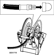
Apply PTFE sealant to the threads of the hose fitting on the long hose, and install the fitting into the connecting tube on the reel (Figure 40).
-
Connect the free end of the long hose to the fitting on the spray gun (Figure 41).
-
Secure the end of the hose with a small hose clamp.
-
Connect the battery cables as follows:
Warning
Incorrect battery cable routing could damage the machine and cables, causing sparks. Sparks can cause the battery gasses to explode, resulting in personal injury.
-
Always disconnect the negative (black) battery cable before disconnecting the positive (red) cable.
-
Always connect the positive (red) battery cable before connecting the negative (black) cable.
-
Connect the positive battery cable to the positive post of the battery; refer to the Operator’s Manual.
-
Connect the negative battery cable to the negative post of the battery; refer to the Operator’s Manual.
-
-
Press the hose wind button, and carefully guide the hose onto the reel moving the hose from side to side to evenly distribute the hose.
Caution
Hands, loose clothing, long hair, and loose jewelry could get caught in the hose and reel while rewinding and cause injury.
-
Keep your hands clear of the reel and hose while it is rewinding.
-
Do not wear loose clothing or loose jewelry and tie up long hair.
-
Checking the Pivoting Hose Reel for Leaks
Warning
Fluid escaping the sprayer system under pressure can penetrate skin and cause injury.
-
Make sure that all hoses and lines are in good condition and all connections and fittings are tight before applying pressure to the sprayer system.
-
Keep your body and hands away from pin hole leaks or nozzles that eject high-pressure fluid.
-
Use cardboard or paper to find fluid leaks.
-
Safely relieve all pressure in the sprayer system before performing any work on the sprayer system.
-
Seek immediate medical attention if fluid is injected into skin.
-
Partially fill the sprayer tank with clean water.
-
Start the engine, set the engine speed to the half-throttle position, and set the switch for the sprayer pump to the ON position; refer to the Operator’s Manual.
-
Ensure the control valve at the end of the section manifold is open.
-
Check for leaks at the manifold, control valve, and hose.
-
Use the rate switch in the switch box to raise the sprayer system pressure at the hose reel.
-
Check the following components for leaks:
-
fittings and couplings
-
pressure gauge and hose-reel valve
-
tubes, hoses, and spray gun
Note: Repair all leaks before operating the sprayer system.
-
-
Close the control valve for the hose reel, set the switch for the sprayer pump to the OFF position, and shut off the engine.
Operation
Warning
Fluid under pressure can penetrate skin and cause injury.
-
Keep your body and hands away from nozzles that eject high-pressure fluid.
-
Do not aim the sprayer at any person or animal.
-
Make sure that all fluid hoses and lines are in good condition and that all connections and fittings are tight before applying pressure to the system.
-
Use cardboard or paper to find leaks.
-
Safely relieve all pressure in the system before performing any work on it.
-
Get immediate medical help if fluid is injected into skin.
-
Hot liquids and chemicals can cause burns or other harm.
Important: Always empty and clean the sprayer immediately after each use. Failure to do so may cause the chemicals to dry or thicken in the lines, clogging the pump and other components.
Clean the spray system after each spraying session. To properly clean the spray system:
-
Use 3 separate rinses.
-
Use a minimum of 189 L (50 US gallons) for each rinse.
-
Use the cleaners and neutralizers as recommended by the chemical manufacturers.
-
Use clean water (no cleaners or neutralizers) for the last rinse.
Switching from Boom-Spray Mode to Hand-Spray Mode
Warning
Driving while using the hand sprayer can cause loss of control, resulting in injury or death. Do not operate the hand sprayer while driving.
-
Stop the machine, turn the booms off, and set the parking brake.
-
At the back of the machine, ensure that the trigger lock on the spray gun is locked.
-
Flip the lever on the control valve to the OPEN position.
-
At the operator's position, turn on the pump.
-
Switch the master boom to the ON position.
-
Set the engine to the desired speed, then set the neutral engine-speed lock.
Important: Do not use a pressure setting higher than 1034 kPa (150 psi) with the hand sprayer.
Spraying with the Hand Sprayer
-
Pull out the desired amount of hose from the reel.
Important: Do not pull out the hose with the spray gun. Always hold onto the hose and pull on it directly. Pulling out the hose with the gun may break the fitting on the gun or damage the hose.
-
Release the trigger lock.
-
Direct the spray gun nozzle at the area to be sprayed and pull the trigger.
-
Release the trigger and set the trigger lock when you are finished.
Switching from Hand-Spray Mode to Boom-Spray Mode
Caution
Hands, loose clothing, long hair, and loose jewelry could get caught in the hose and reel while rewinding and cause injury.
-
Keep your hands clear of the reel and hose while it is rewinding.
-
Do not wear loose clothing or loose jewelry and tie up long hair.
-
Press the rewind button on the hose reel until only a few feet of hose is out of the reel.
-
Flip the lever on the control valve to the CLOSED position.
-
Direct the spray gun nozzle at an area where it is safe to spray, release the trigger lock, and pull the trigger until all remaining fluid is out of the hose, then set the trigger lock.
-
Return the spray gun to the holder on the back of the reel.
-
Return the engine to idle speed.
-
Stop the pump.
Important: Ensure that you flush the spray gun with fresh clean water during your daily cleaning routine (refer to your sprayer Operator's Manual). Failure to properly clean the spray gun may degrade the performance and reliability of the hose reel kit and spray gun.
-
Use the rate switch to set the desired pressure.