|
|
|
|
|
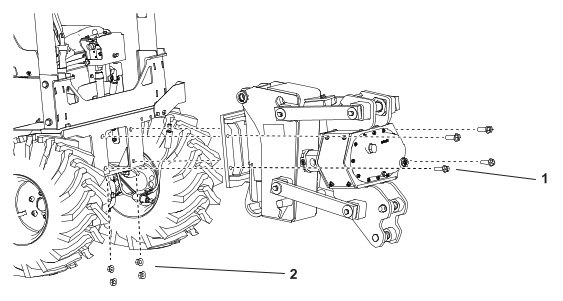
1
|
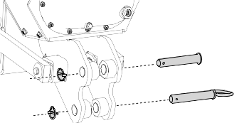
Blade clevis pin
|
|
1
|
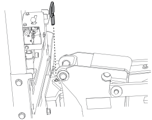
Pin with handle
|
|
1
|
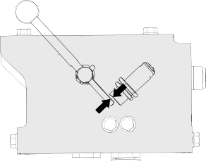
Swing lock pin
|
|
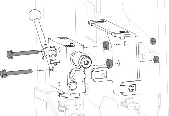
4
|
Bolt (5/8 x 1-1/4 inches)
|
|
4
|
Locknuts (5/8 inch)
|
|
2
|
Lynch pin
|
|
1
|
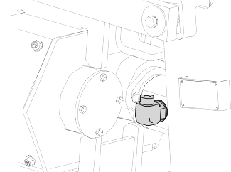
Large connector
|
|
1
|
Small adaptor fitting
|
|
1
|
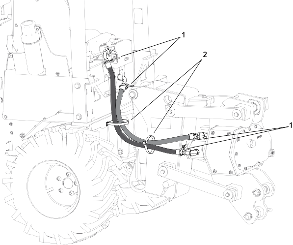
36-inch hydraulic hose
|
|
1
|
33-inch hydraulic hose
|
|
1
|
37-inch abrasion sleeve
|
|
1
|
33-inch abrasion sleeve
|
|
1
|
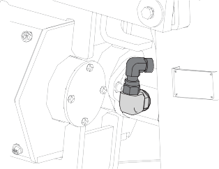
90-degree fitting
|
|
1
|
90-degree fitting
|
|
1
|
90-degree adapter
|
|
2
|
20-inch cable tie
|
|
4
|
7-1/4 inch cable tie
|