Disclaimers and Regulatory Information
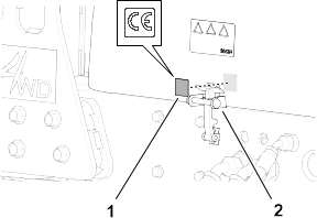
This product complies with
all relevant European directives; for details, please see the separate
product specific Declaration of Conformity (DOC)
sheet.
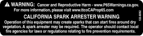
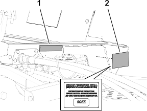
It is a violation of California
Public Resource Code Section 4442 or 4443 to use or operate the engine
on any forest-covered, brush-covered, or grass-covered
land unless the engine is equipped with a spark arrester, as defined
in Section 4442, maintained in effective working
order, or the engine is constructed, equipped, and maintained for
the prevention of fire.
The enclosed engine owner's manual
is supplied for information regarding the US Environmental Protection
Agency (EPA) and the California Emission Control
Regulation of emission systems, maintenance, and warranty. Replacements
may be ordered through the engine manufacturer.
 |
| CALIFORNIA |
| Proposition 65 |
| Diesel engine exhaust and some of its constituents are known to the State of California to cause cancer, birth defects, and other reproductive harm. |
| Battery posts, terminals, and related accessories contain lead and lead compounds, chemicals known to the State of California to cause cancer and reproductive harm. Wash hands after handling. |
| Use of this product may cause exposure to chemicals known to the State of California to cause cancer, birth defects, or other reproductive harm. |
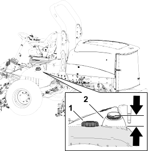
Fuel