Disclaimers and Regulatory Information
This product complies with all relevant European directives; for details, please see the separate product specific Declaration
of Conformity (DOC) sheet.
It is a violation of California Public Resource Code Section 4442 or 4443 to use or operate the engine on any forest-covered,
brush-covered, or grass-covered land unless the engine is equipped with a spark arrester, as defined in Section 4442, maintained
in effective working order, or the engine is constructed, equipped, and maintained for the prevention of fire.
The enclosed engine owner's manual is supplied for information regarding the US Environmental Protection Agency (EPA) and
the California Emission Control Regulation of emission systems, maintenance, and warranty. Replacements may be ordered through
the engine manufacturer.
 |
| |
| CALIFORNIA |
| |
| Proposition 65 |
| |
| Diesel engine exhaust and some of its constituents are known to the
State of California to cause cancer, birth defects, and other reproductive
harm. |
| |
| Battery posts, terminals, and related accessories contain lead and
lead compounds, chemicals known to the State of California to cause
cancer and reproductive harm. Wash hands after handling. |
| |
| Use of this product may cause exposure to chemicals known to the
State of California to cause cancer, birth defects, or other reproductive
harm. |
| |
Intended Use
This machine is a ride-on, reel-blade lawn mower intended to be used by professional, hired operators in commercial applications.
It is primarily designed for cutting grass on well-maintained turf. Using this product for purposes other than its intended
use could prove dangerous to you and bystanders.
Read this information carefully to learn how to operate and maintain your product properly and to avoid injury and product
damage. You are responsible for operating the product properly and safely.
Getting Help
Visit www.Toro.com for product safety and operation training materials, accessory information, help finding a dealer, or to register your product.
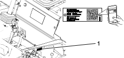
Whenever you need service, genuine Toro parts, or additional information, contact an Authorized Service Dealer or Toro Customer Service and have the model and serial numbers of your product ready. These numbers are located on the serial plate
on your product  . Write the numbers in the space provided.
With your mobile device, you can scan the QR code on the serial number decal (if equipped) to access warranty, parts, and
other product information.
|
Model Number:
|
|
Serial Number:
|
|
Manual Conventions
This manual identifies potential hazards and has safety messages identified by the safety-alert symbol, which signals a hazard
that may cause serious injury or death if you do not follow the recommended precautions.
This manual uses 2 words to highlight information. Important calls attention to special mechanical information and Note emphasizes general information worthy of special attention.
Safety Alert Classifications
The safety-alert symbol shown in this manual and on the machine identifies important safety messages that you must follow
to prevent accidents.
Safety-alert symbol appears above information that alerts you to unsafe actions or situations and is followed by the word
DANGER, WARNING, or CAUTION.
 |
Danger |
|
Danger indicates an imminently hazardous situation which, if not avoided, will result in death or serious injury.
|
Warning |
|
Warning indicates a potentially hazardous situation which, if not avoided, could result in death or serious injury.
|
Caution |
|
Caution indicates a potentially hazardous situation which, if not avoided, may result in minor or moderate injury.
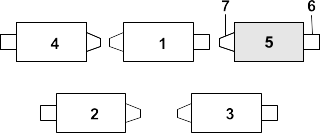
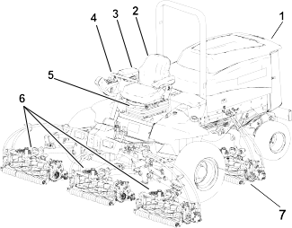
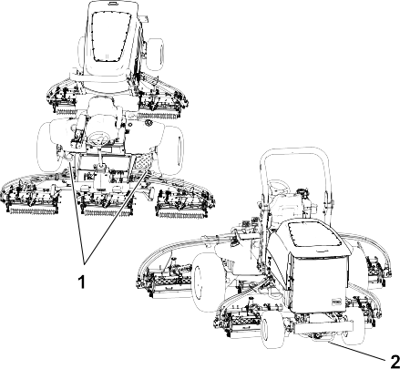
G403841
- Engine hood
- Operator's seat
- Control arm
- Steering wheel
- Seat-adjustment lever
- Front cutting units
- Rear cutting units
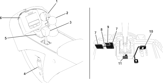
Controls
G467742
-
Key switch
-
Lower mow/raise control lever
-
Throttle-control lever
-
Headlight switch
-
PTO switch
-
InfoCenter
-
Brake pedal
-
Pedal-locking latch
-
Parking-brake pedal
-
Traction pedal
-
Tilt-steering pedal
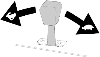
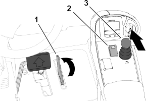
Traction Pedal
G468096
- Move forward—press the top of the pedal.
Note: To achieve no load, maximum ground speed, fully press the top of the pedal while the throttle is in the Fast position.
- Stop the machine—reduce foot pressure on the pedal and allow it to return to the center (neutral) position.
- Move backward—press the bottom of the pedal.
Note: Ground speed depends on how far you press the pedal.
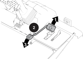
Tilt-Steering Pedal
G453181
Press the tilt-steering pedal and raise or lower the steering tower to a comfortable operating position.
Brake Pedals
The 2 foot pedals operate individual wheel brakes for turning assistance and to aid in obtaining better side hill traction.
Pedal-Locking Latch
The pedal-locking latch connects the pedals together to engage the parking brake.
Parking-Brake Pedal
To engage the parking brake, connect the pedals together with the pedal-locking latch, push down on the right brake pedal
while engaging the toe pedal.
Note: When the parking brake is engaged, the parking brake symbol displays in the InfoCenter.
To release the parking brake, press 1 of the brake pedals until the parking-brake latch retracts.
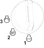
Key Switch
G453721
- Off
- On/preheat
- Start
Lower Mow/Raise Control Lever
G453725
- Lower the cutting units
- Raise the cutting units
Note: The lever also starts and stops the reels when the reels are enabled in the mow mode.
The cutting units cannot be lowered when the mow/transport lever is in the transport position.
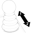
Throttle-Control Lever
G447509
Move the throttle-control lever forward to increase the engine speed and rearward to decrease speed.
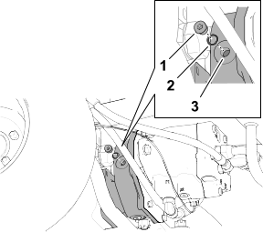
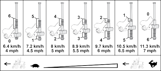
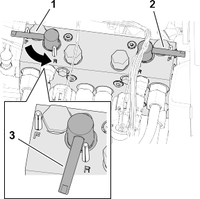
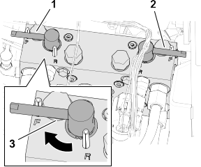
Mow-Speed Limiter
G467875
-
Rotate limiter forward—allows the cutting units to engage and limits the maximum ground speed during mowing.
-
Rotate limiter backward—to achieve maximum ground speed between job sites.
-
Spacers—change the position to adjust mowing ground speed.
-
Forward speed-limiter screw—adjust to limit the amount the traction pedal can be pressed in the forward direction.
-
Reverse speed-limiter screw—adjust to limit the amount the traction pedal can be pressed in the reverse direction.
The speed-limiter screws must stop the traction pedal before the pump reaches full stroke; otherwise, damage to the pump may
occur.
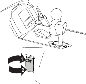
Power Point
G467886
The power point is a 12 V power supply for electronic devices.
Bag Holder
G467887
Use the bag holder for storage.
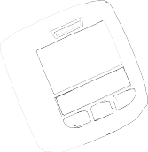
InfoCenter
G453726
The InfoCenter shows information about your machine, such as the operating status, various diagnostics, and other information
about the machine.
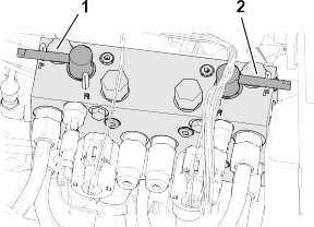
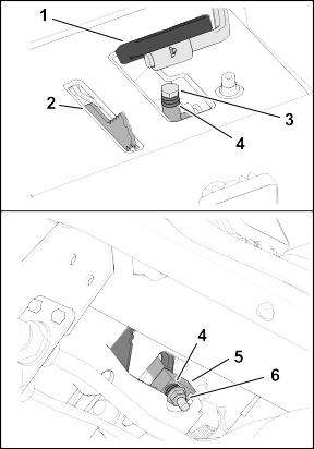
Backlap Levers
Use the backlap levers to control the cutting unit rotation direction when backlapping the reels.
G468066
- Front cutting-unit backlap lever
- Rear cutting-unit backlap lever
Power-Takeoff (PTO) Switch
G468089
- Engage the cutting units
- Disengage the cutting units
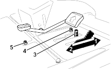
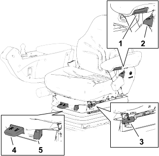
Seat Controls
G423842
-
Armrest adjusting knob
-
Seat back adjusting lever
-
Fore and aft adjusting lever
-
Weight adjusting lever
-
Weight gauge
Armrest Adjustment Knob
Rotate the knob to adjust the seat armrest angle.
Back Adjustment Lever
Move the lever to adjust the seat back angle.
Forward/Backward Lever
Pull out on the lever to slide the seat forward or backward.
Weight-Adjustment Lever
Adjust the seat to your weight. Pull up on the lever to increase the air pressure and push down to decrease the air pressure.
The proper adjustment is attained when the weight gauge is in the green region.
Weight Gauge
The weight gauge indicates when the seat is adjusted to the weight of the operator. Height adjustment is made by positioning
the suspension within the range of the green region.
Specifications
Note: Specifications and design are subject to change without notice.
|
Width of cut, 27-inch cutting units
|
307 cm (121 inches)
|
|
Width of cut, 32-inch cutting units
|
320 cm (126 inches)
|
|
Overall width, 27-inch cutting units down
|
345 cm (136 inches)
|
|
Overall width, 32-inch cutting units down
|
358 cm (141 inches)
|
|
Overall width, cutting units up (transport)
|
239 cm (94 inches)
|
|
Overall length
|
370 cm (146 inches)
|
|
Height with ROPS
|
220 cm (87 inches)
|
|
Track width, front
|
229 cm (90 inches)
|
|
Track width, rear
|
141 cm (55.5 inches)
|
|
Wheelbase
|
171 cm (67.5 inches)
|
|
Net weight (with no cutting units and no fluids)
|
1574 kg (3,470 lb)
|
|
Fuel tank capacity
|
83 L (22 US gallons)
|
Attachments/Accessories
A selection of Toro approved attachments and accessories is available for use with the machine to enhance and expand its capabilities. Contact
your Authorized Service Dealer or authorized Toro distributor or go to www.Toro.com for a list of all approved attachments and accessories.
To ensure optimum performance and continued safety certification of the machine, use only genuine Toro replacement parts and accessories.
Before Operation
Performing Daily Maintenance
Before starting the machine each day, perform the Each Use/Daily procedures listed in the Maintenance Schedule.
Fuel
Fuel Specifications
Never use kerosene or gasoline instead of diesel fuel.
Petroleum Diesel
|
Type
|
Use summer grade diesel fuel (No. 2-D) at temperatures above -7°C (20°F) and winter grade (No. 1-D or No. 1-D/2-D blend) below
that temperature. Use of winter grade fuel at lower temperatures provides lower flash point and cold flow characteristics
which eases starting and reduces fuel filter plugging.
Use of summer grade fuel above -7°C (20°F) contributes toward longer fuel pump life and increased power compared to winter
grade fuel.
|
|
Sulfur content
|
Low (<500 ppm) or ultra low (<15 ppm)
|
|
Minimum Cetane Rating
|
40
|
|
Storage
|
Acquire only enough clean, fresh diesel fuel or biodiesel fuel that you will consume within 180 days. Do not use fuel that
has been stored for more than 180 days.
|
|
Oil and additives
|
Do not add to the fuel
|
Biodiesel
|
Type
|
This machine can also use a biodiesel-blended fuel of up to B20 (20% biodiesel, 80% petroleum diesel).
The petroleum diesel portion should be low or ultra low sulfur.
Use B5 (biodisel content of 5%) or lesser blends in cold weather
|
|
Minimum Cetane Rating
|
40
|
|
Biodiesel Precautions
|
Painted surfaces may be damaged by biodiesel blends.
Monitor seals, hoses, gaskets in contact with fuel as they may degrade over time.
Fuel filter plugging may be expected for a time after converting to biodiesel blended.
For more information on biodiesel, contact your authorized Toro distributor.
|
|
Storage
|
Acquire only enough clean, fresh diesel fuel or biodiesel fuel that you will consume within 180 days. Do not use fuel that
has been stored for more than 180 days.
|
|
Oil and additives
|
Do not add to the fuel
|
| |
|
|
|
Biodiesel fuel must meet:
|
Standard
|
Location
|
|
ASTM D6751
|
USA
|
|
EN 14214
|
European Union
|
|
Blended fuel must meet:
|
ASTM D975
|
USA
|
|
EN 590
|
European Union
|
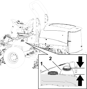
Adding Fuel
-
Park the machine on a level surface, lower the cutting units, shut off the engine, and remove the key.
-
Clean the area around the fuel-tank cap and remove the cap.
-
Fill the tank until the level is to the bottom of the filler neck  with the specified fuel.
-
Install the fuel-tank cap tightly.
Note: If possible, fill the fuel tank after each use. Filling the fuel tank minimizes condensation inside the tank.
Checking the Interlock Switches
|
Caution |
|
If safety interlock switches are disconnected or damaged, the machine could operate unexpectedly, resulting in minor or moderate
injury.
- Do not tamper with the interlock switches.
- Check the operation of the interlock switches daily and replace any damaged switches before operating the machine.
If your machine fails any of the interlock switch checks, contact your authorized Toro distributor.
Preparing the Machine
-
Drive the machine slowly to an open area.
-
Lower the cutting units, shut off the engine, and engage the parking brake.
Checking the Traction Pedal Start-Interlock
-
Sit in the operator’s seat and engage the parking brake.
-
Press the PTO switch to the Disengage position.
-
Press the traction pedal and rotate the key to the Start position.
Note: The engine should not start with the traction pedal pressed.
Checking the PTO-Start Interlock
-
Sit in the operator’s seat.
-
Press the PTO switch to the Engage position.
-
Rotate the key to the Start position.
Note: The engine should not start with the PTO switch in the Engage position.
Checking the PTO-Run Interlock
-
Sit in the operator’s seat and press the PTO switch to the Disengage position.
-
Start the engine and rise from the seat.
-
Press the PTO switch to the Engage position.
Note: The PTO should not run when you are out of the operator’s seat.
Checking the Parking Brake and Traction Pedal Run-Interlock
-
Sit in the operator’s seat and engage the parking brake.
-
Press the PTO switch to the Disengage position.
-
Start the engine.
-
Press the traction pedal.
Note: The engine should shut off when the parking brake is engaged and the traction pedal is pressed.
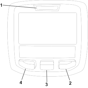
Overview of the InfoCenter Display
The InfoCenter LCD display shows information about your machine, such as the operating status, various diagnostics, and other
information about the machine. There is a splash screen and main information screen of the InfoCenter. You can switch between
the splash screen and main information screen, at any time, by pressing any of the InfoCenter buttons and then selecting the
appropriate directional arrow.
G446183
-
Indicator light
-
Right button
-
Middle button
-
Left button
- Left Button, Menu Access/Back Button—press this button to access the InfoCenter menus. You can use it to back out of any menu you are currently using.
- Middle Button—use this button to scroll down menus.
- Right Button—use this button to open a menu where a right arrow indicates additional content.
- Manual Fan Reversal—activated by pressing the left and right buttons simultaneously.
- Beeper—activated when lowering the decks or for advisories and faults.
Note: The purpose of each button may change depending on what is required at the time. Each button is labeled with an icon displaying
its current function.
InfoCenter Display Icons
|
SERVICE DUE
|
Indicates when scheduled service should be performed
|
|
|
The range is high.
|
|
|
Hours remaining until service
|
|
|
Neutral
|
|
|
Reset the service hours
 * * |
|
|
The range is low.
|
|
|
Hour meter
|
|
|
Engine-coolant temperature (°C or °F)
|
|
|
Info icon
|
|
|
Temperature (hot)
|
|
|
Fast
|
|
|
The PTO is engaged.
|
|
|
Slow
|
|
|
Not allowed
|
|
|
Air intake heater is active
|
|
|
Start the engine.
|
|
|
Raise the cutting units.
|
|
|
Stop the engine.
|
|
|
Lower the cutting units.
|
|
|
Engine
|
|
|
Sit in the seat.
|
|
|
Key switch
|
|
|
The parking brake is on.
|
|
|
The cutting units are lowering.
|
|
|
CAN bus
|
|
|
The cutting units are raising.
|
|
|
Bad or failed
|
|
|
PIN passcode
|
|
|
Output of TEC controller or control wire in harness
|
|
|
InfoCenter
|
|
|
Release the switch.
|
|
|
Bulb
|
|
|
Switch
|
|
|
Change to the indicated state.
|
|
|
High: over allowed range
|
|
|
Hydraulic fluid temperature
|
|
|
Low: under allowed range
|
|
|
Fan is reversed
|
|
|
Out of range
|
|
|
|
| |
|
|
|
|
|
Symbols are often combined to form sentences. Some examples are shown below
|
|
|
Put the machine into Neutral.
|
|
|
Engine start is denied.
|
|
|
Engine shutdown
|
|
|
Engine coolant is too hot.
|
 or or  |
Sit down or set parking brake
|
|
|
Hydraulic fluid is too hot.
|
* Accessible only by entering PIN
|
Overview of the Menus
To access the InfoCenter menu system, press the menu access button while at the main screen. This brings you to the main menu.
Refer to the following tables for a synopsis of the options available from the menus:
|
Faults
|
The Faults menu contains a list of the recent machine faults. Refer to the Service Manual or your Authorized Toro Distributor for more information on the Faults menu and the information contained there.
|
|
Service
|
The Service menu contains information on the machine such as hours of use, counters, and other similar numbers.
|
|
Diagnostics
|
The Diagnostics menu displays the state of each machine switch, sensor, and control output. You can use this to troubleshoot
certain issues as it will quickly tell you which machine controls are on and which are off.
|
|
Settings
|
The Settings menu allows you to customize and modify configuration variables on the display.
|
|
About
|
The About menu lists the model number, serial number, and software version of your machine.
|
|
Hours
|
Lists the total number of hours that the machine, engine and PTO have been on, as well as the number of hours the machine
has been transported and service due.
|
|
Counts
|
Lists numerous counts the machine has experienced.
|
|
Cutting Units
|
Indicates the inputs, qualifiers, and outputs for raising and lowering the cutting units.
|
|
Hi/Low Range
|
Indicates the inputs, qualifiers, and outputs for driving in transport mode.
|
|
PTO
|
Indicates the inputs, qualifiers, and outputs for enabling the PTO circuit.
|
|
Engine Run
|
Indicates the inputs, qualifiers, and outputs for starting the engine.
|
|
Backlap
|
Indicates the inputs, qualifiers, and outputs for operating the backlap function.
|
|
Units
|
Controls the units used on the display. The menu choices are English or Metric.
|
|
Language
|
Controls the language used on the display*.
|
|
LCD Backlight
|
Controls the brightness of the LCD display.
|
|
LCD Contrast
|
Controls the contrast of the LCD display.
|
|
Front Backlap Reel Speed
|
Controls the speed of the front reels in backlap mode.
|
|
Rear Backlap Reel Speed
|
Controls the speed of the rear reels in backlap mode.
|
Protected Menus 
|
Allows a person (superintendent/mechanic) authorized by your company with the PIN code to access protected menus.
|
Auto Idle
|
Controls the amount of time allowed before returning the engine to low idle when the machine is stationary
|
Blade Count
|
Controls the number of blades on the reel for reel speed.
|
Height of cut (HOC)
|
Controls the height of cut (HOC) for determining the reel speed.
|
F Reel RPM
|
Displays the calculated reel speed position for the front reels. The reels can also be manually adjusted.
|
R Reel RPM
|
Displays the calculated reel speed position for the rear reels. The reels can also be manually adjusted.
|
Mow Speed
|
Controls the ground speed for determining the reel speed
|
* Only "operator-faced" text is translated. Faults, Service, and Diagnostics screens are "service-faced". Titles are be in
the selected language, but menu items are in English.
Protected under Protected Menus—accessible only by entering PIN
|
Model
|
Lists the model number of the machine.
|
|
SN
|
Lists the serial number of the machine.
|
|
Machine Controller Revision
|
Lists the software revision of the master controller.
|
|
Display Revision
|
Lists the software revision of the display.
|
|
CAN Bus
|
Lists the machine communication bus status.
|
Protected Menus
There are operating configuration settings that are adjustable within the Settings Menu of the display. To lock these settings, use the Protected Menu.
Note: At the time of delivery, the initial password code is programmed by your distributor.
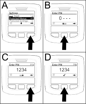
Accessing Protected Menus
Note: The factory default PIN code for you machine is either 0000 or 1234.
If you changed the PIN code and forgot the code, contact your authorized Toro distributor for assistance.
-
From the Main Menu, use the center button to scroll down to the Settings Menu and press the right button.
-
In the Settings Menu, use the center button to scroll down to the Protected Menu and press the right button  .
.
-
To enter the PIN code, press the center button  until the correct first digit appears, then press the right button
  to move on to the next digit. Repeat this step until the last digit is entered and press the right button once more.
-
Press the middle button  to enter the PIN code. Wait until the red indicator light of the display illuminates.
Note: If the display accepts the PIN code and the protected menu is unlocked, the word “PIN” displays in the upper right corner of the screen.
-
To lock the protected menu, rotate the key switch to the Off position and then to the On position.
Setting the Auto Idle
-
In the Settings Menu, scroll down to Auto Idle.
-
Press the right button to change the auto idle time between Off, 8S, 10S, 15S, 20S, and 30S.
Setting the Blade Count
-
In the Settings Menu, scroll down to Blade Count.
-
Press the right button to change the blade count between 5, 8, or 11 blade reels.
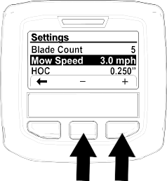
Setting the Mow Speed
-
In the Settings Menu, scroll down to Mow Speed and press the right button.
-
Use the center and right button to select the appropriate mow speed set on the mechanical mow-speed limiter on the traction
pedal.
-
Press the left button to exit mow speed and save the setting.
Setting the Height of Cut (HOC)
-
In the Settings Menu, scroll down to HOC.
-
Press the right button to select HOC.
-
Use the center and right button to select the HOC setting. If the exact setting is not displayed, select the nearest HOC setting
from the list displayed.
-
Press the left button to exit HOC and save the setting.
During Operation
Starting the Engine
Bleed the fuel system if any of the following situations have occurred:
- The engine has shut off because the machine ran out of fuel.
- Maintenance was performed on the fuel system components.
-
Sit in the operator’s seat, engage the parking brake, and ensure that your foot is off the traction pedal.
-
Move the engine-throttle control to the Slow position.
-
Turn the key to the Run position.
The glow-plug indicator displays in the InfoCenter.
-
When the glow indicator shuts off, turn the key to the Start position.
Do not run the starter motor more than 15 seconds at a time, or premature starter failure may result. If the engine fails
to start after 15 seconds, turn the key to the Off position, check the controls and procedures, wait 15 additional seconds, and repeat the starting procedure.
When the temperature is less than -7°C (20°F), the starter motor can be run for 30 seconds on then 60 seconds off for 2 attempts.
-
When the engine starts, release the key.
-
Adjust the engine speed.
Shutting Off the Engine
-
Park the machine on a level surface.
-
Press the PTO switch to the Disengage position.
-
Move the engine-throttle control to the Slow position.
-
Engage the parking brake.
-
Lower the cutting units.
Lowering the cutting units relieves the hydraulic load from the system, prevents wear on system parts, and prevents accidental
lowering of the cutting units.
-
Rotate the key to Off and remove the key.
-
Wait for all moving parts to stop.
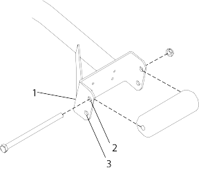
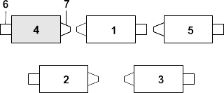
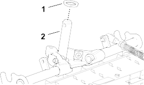
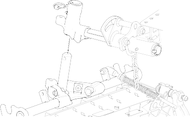
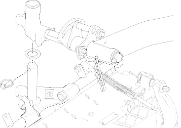
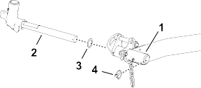
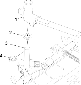
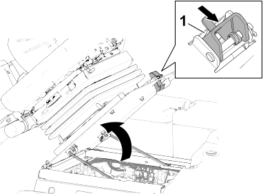
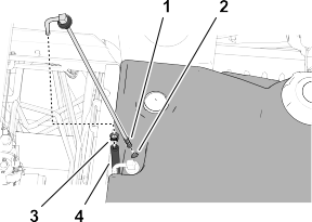
Locking the Cutting-Unit Pivot
Cutting Grass on a Hill Side
Lock the cutting-unit pivots to prevent the cutting units from rotating downhill when cutting across the face of a hill.
-
Secure the carrier frame  of the cutting unit to the pivot yoke with the snapper pin .
-
Repeat step 1 at the other cutting units.
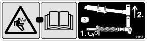
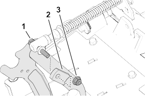
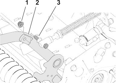
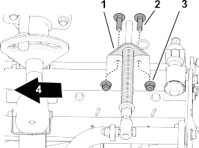
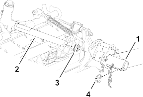
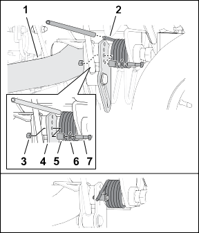
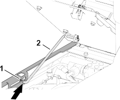
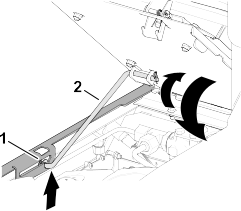
Adjusting the Turf-Compensation Spring
The turf-compensation spring transfers the weight from the front roller to the rear roller. This helps to reduce a wave pattern
in the turf, also known as marcelling or bobbing.
Make spring adjustments with the cutting unit mounted to the traction unit, pointing straight ahead and lowered to the ground.
-
Make sure that the hairpin is installed in the rear hole in the spring rod .
Note: When servicing the cutting unit, move the hairpin to the spring-rod hole next to the turf-compensation spring .
-
Tighten the hex nuts  on the front end of the spring rod until the compressed length of the spring is 15.9 cm (6.25 inches).
Note: When operating on rough terrain decrease the spring length by 13 mm (1/2 inch). Ground following will be slightly decreased.
Note: The turf compensation setting will need to be reset if the HOC setting or the Aggressiveness of Cut setting is changed.
Cutting Grass with the Machine
-
Drive the machine to the mowing area and align the machine outside the cutting area for the first cutting pass.
-
Ensure that the PTO switch is set to the Disengage position.
G468221
-
Engine-throttle control
-
PTO switch
-
Mow/raise control lever
-
Use your foot to move the lever for the mow-speed limiter forward, to the Mow position.
G423890
-
Mow-speed limiter
-
Move the engine-throttle control to the Fast position.
-
Press the PTO switch to the Engage position.
-
Begin driving the machine into the cutting area and move the lower mow/raise control lever forward.
Note: The cutting units start running as they lower. The front cutting units are timed to lower before the rear cutting units.
-
When you complete the mowing pass, move the lever for the mow-speed limiter backward to lift the cutting units.
-
Perform a tear-shaped turn to quickly line up for your next pass.
Driving the Machine in Transport Mode
-
Press the PTO switch to the Disengage position.
-
Move the lower mow/raise control lever backward to raise the cutting units (transport position).
-
Move the lever for the mow-speed limiter backward to the Transport position.
-
Press the traction pedal to drive the machine.
Be careful when driving between objects so that you do not accidentally damage the machine or cutting units. Use extra care
when operating the machine on slopes. Drive slowly and avoid sharp turns on slopes to prevent a rollover.
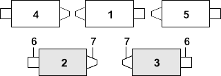
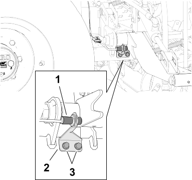
Adjusting the Cutting-Unit Counterbalance
Rear Cutting Units
|
Caution |
|
The springs are under tension, and adjusting them could result in minor or moderate personal injury.
Use caution when adjusting the springs.
Adjust the amount of counterbalance force applied to the rear cutting-units to help compensate for different turf conditions,
and to maintain a uniform height of cut in rough conditions or in areas of thatch buildup.
Adjust the counterbalance force of each torsion spring to 1 of 4 settings. Each increment increases or decreases the counterbalance
force on the cutting unit by 2.3 kg (5 lb).
Note: To remove all counterbalance force, position the long leg of the torsion spring below the bolt, washer, spacer, and locknut.
-
Park the machine on a level surface, lower the cutting units, engage the parking brake, shut off the engine, and remove the
key.
-
Insert a tube or similar object over the long leg of the spring, and lift the spring leg to relieve pressure on the spacer.
Note: Have another person help by lifting and lowering the spring leg.
G424029
-
Lift arm (rear—cutting unit #2 or #3)
-
Torsion spring
-
Locknut
-
Lift-arm plate
-
Spacer
-
Washer
-
Bolt
-
While holding the spring, remove the bolt, washer, and locknut from the lift plate.
-
Align the spring leg above the desired hole location.
-
Install the bolt, washer, spacer, and locknut at the hole location.
-
Slowly lower the spring leg onto the spacer.
-
Repeat steps 2 through 6 at the rear cutting-unit-lift arm.
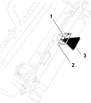
Adjusting the Cutting Unit-Turnaround Height
The lift-arm switch is located behind the right, front lift arm (cutting unit #5).
-
Park the machine on a level surface, lower the cutting units, engage the parking brake, shut off the engine, and remove the
key.
-
Loosen the 2 flange-head screws that secure the switch bracket to the carrier frame for the front cutting unit-lift arms.
-
Move the switch bracket as follows:
- To increase the cutting unit-turnaround height, move the bracket up.
- To decrease the cutting unit-turnaround height, move the bracket down.
-
Tighten the 2 flange-head screws.
Folding the Roll Bar
- Keep all nuts, bolts, and screws correctly torqued ensure that the equipment is in safe working condition.
- Replace worn or damaged parts for safety.
- Ensure that the seat belt and mountings are in safe working order.
- Wear the seat belt when the roll bar is raised and no seat belt when the roll bar is lowered.
You can fold the roll bar down to allow access into areas with restricted height.
|
Warning |
|
The machine does not have a rollover protection system (ROPS) when the roll bar is folded down and should not be considered
a ROPS.
Do not wear a seatbelt when the roll bar is lowered.
|
Caution |
|
When lowering and raising the roll bar, your fingers may get pinched between the machine and the roll bar, which could result
in minor or moderate injury.
Use caution when lowering and raising the roll bar.
|
Warning |
|
The roll bar is an integral safety device. It does not protect you from injury or even death from a rollover unless it is
secured in the raised position and you are wearing the seat belt.
- Keep the roll bar in the raised position whenever you operate the machine.
- Lower the roll bar temporarily only when necessary, then secure it in the raised position as soon as possible before continuing
operation.
The roll bar is an integral safety device. Keep the roll bar in the raised position when operating the mower. Lower the roll
bar temporarily only when absolutely necessary.
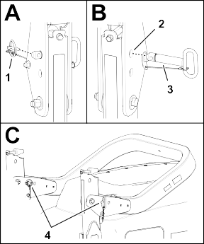
-
Park the machine on a level surface, lower the cutting units, engage the parking brake, shut off the engine, and remove the
key.
-
Remove the lynch pins that secure the roll-bar pins at each side of the roll bar.
G424045
-
Lynch pin
-
Upper holes (pivot brackets)
-
Roll-bar pin
-
Roll-bar and lynch pins (lower holes—pivot brackets)
-
Support the weight of the upper roll-bar tube while removing roll-bar pins from the pivot brackets.
-
Carefully lower the upper roll-bar tube until it rests on the stops.
-
Insert the roll-bar pins into the lower holes in the pivot brackets, and secure the roll-bar pins to the brackets with the
lynch pins.
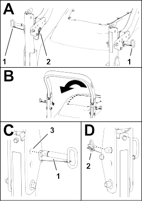
Raising the Roll Bar
|
Warning |
|
The ROPS protection system may not be effective if the roll-bar pins are loose, which, in a rollover, could result in death
or serious injury.
When the roll bar is in the raised position, you must install both roll-bar pins and both lynch pins to ensure full ROPS protection.
-
Park the machine on a level surface, lower the cutting units, engage the parking brake, shut off the engine, and remove the
key.
-
Remove the lynch pins that secure the roll-bar pins at each side of the roll bar.
-
Removing roll-bar pins from the pivot brackets .
-
Carefully lift the upper roll-bar tube until the holes in the pivot bracket align with the holes in the lower roll-bar tube.
-
Insert the roll-bar pins into the holes in the pivot bracket and lower roll-bar tube.
-
Secure the roll-bar pins to the brackets and lower roll-bar tubes with the lynch pins.
Operating Tips
Becoming Familiar with the Machine
- Before mowing grass, practice operating the machine in an open area.
- Start and shut off the engine.
- Operate in forward and reverse.
- Lower and raise the cutting units and engage and disengage the cutting units.
- When you become more familiar with the machine, practice operating up and down slopes at different speeds.
Overview of the Warning System
If the InfoCenter displays an operator advisory or a fault code during operation, stop the machine immediately and correct
the problem before continuing operation. Serious damage could occur if you operate the machine with a malfunction.
After Operation
Pushing or Towing the Machine
|
Warning |
|
While the tow bypass valve is open, the machine could unintentionally move, resulting in death or serious injury.
When you are not pushing or towing the machine, engage the parking brake.
In an emergency, you can move the machine by opening tow bypass valve of the traction hydraulic pump, installing a hydraulic
hose to bypass the check valve, and then pushing or towing the machine.
If you need to push or tow your machine, you may need to move it both forward and in reverse. To ensure that the drive system
does not become damaged from pushing or towing, it is best to prepare the machine for both forward and reverse pushing or
towing.
Preparing the Machine to Push or Tow in Reverse
Install the Reverse Tow Kit
Required Parts (purchased separately): Reverse Tow Kit, Toro Part No. 136-3620
If you need to push or tow the machine in reverse, you must first bypass the check valve in the 4-wheel-drive manifold.
-
Park the machine on a level surface, engage the parking brake, lower the cutting units, shut off the engine and remove the
key.
-
Loosely assemble the bypass hose and straight fittings of the reverse tow kit; refer to the Reverse Tow Kit Installation Instructions.
-
Remove the dust cap and the test fitting from the test port of the reverse traction tube.
-
Assemble the straight fitting of the bypass hose to the test port, and tighten the fitting and hose.
-
Remove the #6 hex-socket plug from the unmarked port (located between the fittings in port M8 and port P2) of the rear-traction
manifold.
-
Assemble the other straight fitting of the bypass hose into the unmarked rear-traction manifold port, and tighten the fitting
and hose.
-
Open the tow-bypass valve by rotating it 90° (1/4 turn) in either direction.
Note: Note the position of the valve when opening and closing it.
-
Push or tow the machine.
Do not push or tow the machine faster than 3 to 4.8 km/h (2 to 3 mph) or for more than 0.4 km (1/4 mile), because damage to
the hydraulic system may occur. The bypass valve must be open whenever you push or tow the machine.
Preparing the Machine for Operation
Remove the Reverse Tow Kit
-
Park the machine on a level surface, engage the parking brake, lower the cutting units, shut off the engine and remove the
key.
-
Remove the straight fitting and bypass hose of the reverse tow kit from the test port of the reverse traction tube; refer
to the Reverse Tow Kit Installation Instructions.
-
Install the test fitting and dust cap to the test port.
-
Remove the other straight fitting of the bypass hose from the unmarked (located between the fittings in port M8 and port P2)
rear-traction manifold port.
-
Install the new #6 hex-socket plug from the reverse tow kit into the unmarked port of the rear-traction manifold.
-
Close the tow-bypass valve by rotating it back 90° (1/4 turn) before starting the engine.
Note: Do not exceed 7 to 11 N∙m (5 to 8 ft-lb) torque to close the valve.
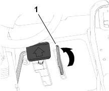
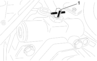
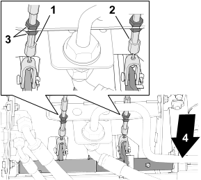
Pushing or Towing the Machine Forward
-
Open the hood and remove the center shroud.
-
Open the tow-bypass valve by rotating it 90° (1/4 turn) in either direction.
Note: Note the position of the valve when opening and closing it.
-
Push or tow the machine forward.
Do not push or tow the machine faster than 3 to 4.8 km/h (2 to 3 mph) or for more than 0.4 km (1/4 mile), because damage to
the hydraulic system may occur. The bypass valve must be open whenever you push or tow the machine.
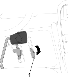
-
When the machine is ready for operation, close the tow-bypass valve by rotating it back 90° (1/4 turn) before starting the
engine.
Note: Do not exceed 7 to 11 N∙m (5 to 8 ft-lb) torque to close the valve.
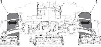
Tie-Down Point Locations
G424086
-
Front tie-down points
-
Rear tie-down point
Hauling the Machine
-
Follow the tips below when hauling the machine.
- Use full-width ramps for loading the machine onto a trailer or truck.
- Tie the machine down securely.
Note: Determine the left and right sides of the machine from the normal operating position.
Note: Download a free copy of the electrical or hydraulic schematic by visiting www.Toro.com and searching for your machine from the Manuals link on the home page.
Refer to your engine owner’s manual and cutting unit Operator's Manual for additional maintenance procedures.
Recommended Maintenance Schedule
|
After the first 8 hours
|
|
- |
- |
- |
|
After the first 50 hours
|
|
- |
- |
- |
|
After the first 200 hours
|
|
- |
- |
- |
|
Before each use or daily
|
|
- |
- |
- |
|
|
- |
- |
- |
|
|
108-3814 |
1 |
Outer air filter |
|
108-3816 |
1 |
Inner air filter |
|
|
121-6393 |
1 |
10W-30 Premium Engine Oil (5 gallons) |
|
121-6392 |
1 |
10W-30 Premium Engine Oil (55 gallons) |
|
121-6395
|
1 |
15W-40 Premium Engine Oil (5 gallons) |
|
121-6394
|
1 |
15W-40 Premium Engine Oil (55 gallons) |
|
|
- |
- |
- |
|
|
- |
- |
- |
|
|
- |
- |
- |
|
|
- |
- |
- |
|
|
- |
- |
- |
|
|
- |
- |
- |
|
|
- |
- |
- |
|
|
- |
- |
- |
|
Every 50 hours
|
|
108-1190 |
1 |
Premium all-purpose grease (14 oz) |
|
|
- |
- |
- |
|
Every 100 hours
|
|
120-5824
|
1 |
Alternator belt |
| |
|
Every 200 hours
|
|
-
|
- |
- |
|
Every 400 hours
|
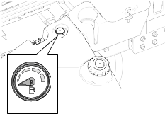
Service the air cleaner (more frequently in extremely dirty or dusty conditions). Service the air cleaner earlier if the air-cleaner indicator shows
red.
|
108-3814 |
1 |
Outer air filter |
|
108-3816 |
1 |
Inner air filter |
|
|
- |
- |
- |
|
|
110-9049 |
1 |
Fuel system water filter |
| |
|
|
- |
- |
- |
|
|
- |
- |
- |
|
|
- |
- |
- |
|
|
- |
- |
- |
|
Every 800 hours
|
|
- |
- |
- |
|
|
- |
- |
- |
|
|
- |
- |
- |
|
|
- |
- |
- |
|
|
75-1310 |
1 |
Hydraulic filter |
|
94-2621 |
1 |
Hydraulic filter |
If you are not using the recommended hydraulic fluid or have ever filled the reservoir with an alternative fluid, change the hydraulic fluid.
|
133-8086 |
1 |
PX Extended Life Hydraulic Fluid (5 gallons) |
|
133-8087 |
1 |
PX Extended Life Hydraulic Fluid (5 gallons) |
|
Every 1,000 hours
|
|
75-1310 |
1 |
Hydraulic filter |
|
94-2621 |
1 |
Hydraulic filter |
|
Every 2,000 hours
|
If you are using the recommended hydraulic fluid, change the hydraulic fluid. |
133-8086 |
1 |
PX Extended Life Hydraulic Fluid (5 gallons) |
|
133-8087 |
1 |
PX Extended Life Hydraulic Fluid (55 gallons) |
|
Before storage
|
|
- |
- |
- |
|
Every 2 years
|
Flush and replace the cooling system fluid (take the machine to an Authorized Service Dealer or Distributor or refer to the
Service Manual).
|
- |
- |
- |
|
Replace the hydraulic hoses (take the machine to an Authorized Service Dealer or Distributor or refer to the Service Manual).
|
- |
- |
- |
|
Replace the coolant hoses (take the machine to an Authorized Service Dealer or Distributor or refer to the Service Manual).
|
- |
- |
- |
Daily Maintenance Checklist
Duplicate this page for routine use.
|
Check the safety interlock operation.
|
|
|
|
|
|
|
|
|
Check the brake operation.
|
|
|
|
|
|
|
|
|
Check the levels of the engine oil and fuel.
|
|
|
|
|
|
|
|
|
Check the cooling-system fluid level.
|
|
|
|
|
|
|
|
|
Drain the water/fuel separator.
|
|
|
|
|
|
|
|
|
Check the air-filter service indicator.
|
|
|
|
|
|
|
|
|
Check the radiator, oil cooler, and screen for debris.
|
|
|
|
|
|
|
|
|
Check for unusual engine noises.1
|
|
|
|
|
|
|
|
|
Check for unusal operating noises.
|
|
|
|
|
|
|
|
|
Check the fluid level of the hydraulic system.
|
|
|
|
|
|
|
|
|
Check the hydraulic hoses for damage.
|
|
|
|
|
|
|
|
|
Check the fluid for leaks.
|
|
|
|
|
|
|
|
|
Check the tire pressure.
|
|
|
|
|
|
|
|
|
Check the instrument operation.
|
|
|
|
|
|
|
|
|
Check the reel-to-bedknife adjustment.
|
|
|
|
|
|
|
|
|
Check the height-of-cut adjustment.
|
|
|
|
|
|
|
|
|
Lubricate all grease fittings.2
|
|
|
|
|
|
|
|
|
Touch-up damaged paint.
|
|
|
|
|
|
|
|
-
Check the glow plug and injector nozzles if the engine starts hard, produces excess smoke, or runs rough.
-
Immediately after every washing, regardless of the interval listed
|
Refer to your engine operator’s manual for additional maintenance procedures.
|
Notation for Areas of Concern
Pre-Maintenance Procedures
Preparing for Maintenance
-
Park the machine on a level surface, lower the cutting units, and engage the parking brake.
-
Shut off the engine, remove the key, and wait for all moving parts to stop.
Opening the Hood
-
Release the 2 hood latches and rotate open the hood.
Closing the Hood
-
Carefully rotate the hood closed and secure it with the 2 hood latches .
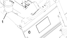
Accessing the Battery Compartment
-
Release the rubber latch from the battery-compartment cover and rotate the cover open.
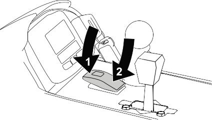
Lowering the Seat
-
Rotate the seat slightly, and lift the prop rod out of the detent of the seat support slot .
-
Carefully lower the seat until it latches securely.
Jacking Point Locations
Note: Support the machine with jack stands whenever you work under the machine.
Use the following as machine-lift points:
- Front—the frame of the machine, forward of the wheel-drive motors.
Do not support the machine at the wheel-drive motors. Keep the lifting equipment clear of hydraulic tubing and hoses.
- Rear—the center of the axle.
Note: Locate the jack stands of the specified capacity at both sides of the gear case and under the axle.
Do not support the machine at the tie rod.
Lubrication
Greasing the Bearings and Bushings
The machine has grease fittings that must be lubricated regularly. Dusty and dirty operating conditions could cause dirt to
get into the bearings and bushings, resulting in accelerated wear. Lubricate the grease fittings immediately after every washing,
regardless of the interval specified.
-
Prepare the machine for maintenance.
-
Grease all machine fittings with No. 2 lithium grease.
Grease Fitting Locations
Grease Specification: No. 2 lithium grease
|
Brake shaft pivot bearings (5)
|
|
|
Rear axle-pivot bushing and steering cylinder
|
|
|
Steering cylinder ball joints (2)
Tie rod ball joints (2)
King pin bushings (2)
Note: The top fitting on the king pin should only be lubricated annually (2 pumps)
|
G452387
-
Top fitting on king pin
|
|
Lift arm bushings (1 per cutting unit)
Lift cylinder bushings (2 per cutting unit)
|
|
|
Lift arm pivot bushings (1 per cutting unit)
Cutting unit carrier frame (2 per cutting unit)
Cutting unit lift arm pivot (1 per cutting unit)
|
|
Engine Maintenance
Engine Oil Specifications
Oil Type
Use high-quality, low-ash engine oil that meets or exceeds API service category CH-4 or higher.
Use the following engine oil viscosity grade:
- Preferred oil: SAE 15W-40 [-17°C (above 0°F)]
- Alternate oil: SAE 10W-30 or 5W-30 (all temperatures)
Toro Premium Engine Oil is available from your authorized Toro distributor in either 15W-40 or 10W-30 viscosity grades.
Crankcase Capacity
Approximately 9.5 L (10.0 US qt) with the filter
Checking the Engine-Oil Level
Note: Check the oil when the engine is cool. If the engine is warm, wait 10 minutes before checking.
The engine is shipped with oil in the crankcase; however, check the oil level before and after you first start the engine.
If the oil level is below the lower limit mark on the dipstick, add oil gradually until the level reaches the upper limit
mark on the dipstick.
Keep the engine-oil level between the upper and lower limits on the dipstick. Overfilling or underfilling the engine oil may
cause severe engine damage.
-
Prepare the machine for maintenance.
-
Unlatch and open the hood.
-
Check the level of the engine oil.
-
Close and latch the hood.
Changing the Engine Oil and Filter
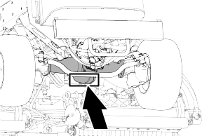
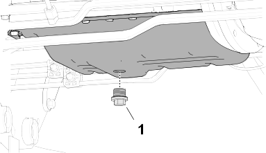
Draining the Engine Oil
-
Prepare the machine for maintenance.
-
Remove the oil fill cap.
-
Align a drain pan under the drain plug .
-
Remove the drain plug and let the oil drain into the pan.
-
When oil stops draining from the engine, install the drain plug and torque it to 54 to 63 N∙m (40 to 47 ft-lb).
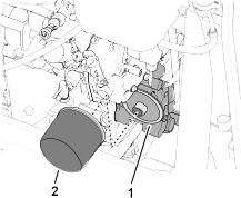
Changing the Oil Filter
-
Rotate the oil filter counterclockwise to remove it.
-
Wipe the filter adapter clean.
-
Apply a light coat of clean oil to the seal of the new filter.
-
Thread the filter onto the filter adapter until the filter contacts the adapter, then tighten the filter an additional turn.
Note: Do not overtighten the filter.
-
Add oil to the crankcase and install the filler cap.
Servicing the Air Cleaner
Removing the Filter
Service the air-cleaner filter only when the service indicator displays a red band. Changing the air filter before it is necessary
only increases the chance of dirt entering the engine when the filter is removed.
Make sure that the cover is seated correctly and seals with the air-cleaner body.
-
Prepare the machine for maintenance.
-
Open the hood.
-
Check the air-cleaner body for wear or damage which could cause an air leak. Check the whole intake system for leaks, damage,
or loose hose clamps.
Note: Replace a worn or damaged air cleaner and intake-system parts.
-
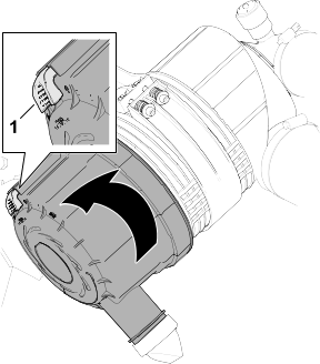
Pull the latch outward, rotate the air-cleaner cover counterclockwise, and remove the cover.
-
Before removing the filter, use low-pressure air—275 kPa (40 psi), clean and dry—to help remove large accumulations of debris packed between outside of primary filter and the air-cleaner housing.
Avoid using high-pressure air, which could force dirt through the filter into the intake tract.
-
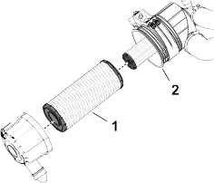
Remove the primary filter from the air-cleaner housing .
Note: Do not clean the primary filter.
Installing the Filter
-
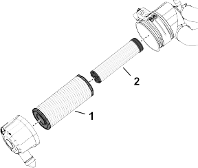
Check the safety-filter element . If it is dirty, replace it.
Never attempt to clean the safety filter. Replace the safety filter with a new one after every 3 primary filter services.
-
Inspect the new filter for shipping damage, checking the sealing end of the filter element and the body of the air filter.
Do not use a damaged filter element.
-
Assemble the primary-filter element . Apply pressure to the outer rim of the element to seat it in the air-filter housing.
Do not apply pressure to the flexible center of the filter.
-
Remove the dust-ejector valve from the air-cleaner cover, clean the cavity, and install the ejector valve to the cover.
-
Assemble the cover onto the air-cleaner housing, aligning the dust-ejector valve in a downward position—between approximately 5 o’clock to 7 o’clock when viewed from the end.
-
If a red band displays in the service indicator, press the reset button at the end of the indicator.
-
Close and latch the hood.
Fuel System Maintenance
Inspecting the Fuel Lines and Connections
-
Prepare the machine for maintenance.
-
Open the hood.
-
Inspect the fuel lines for wear, deterioration, damage, or loose fittings.
Note: Repair or replace any worn or damaged fuel lines; tighten any loose fittings.
-
Close and latch the hood.
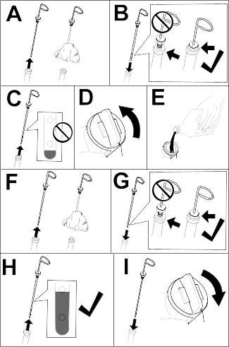
Draining the Fuel/Water Separator
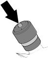
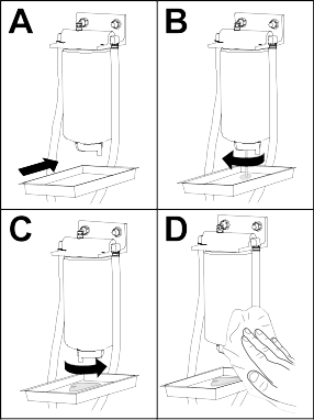
-
Prepare the machine for maintenance.
-
Drain the water separator as shown.
-
Start the engine, check for leaks, and shut off the engine.
Note: Repair all fuel leaks.
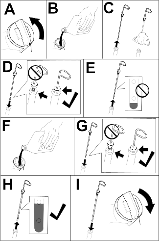
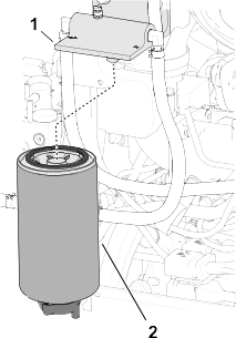
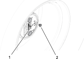
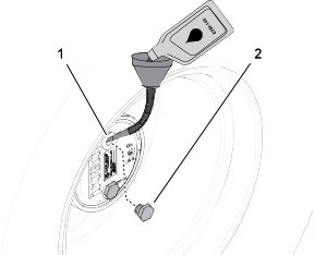
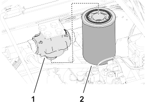
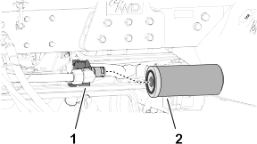
Replacing the Water-Separator Filter
-
Fully drain the fuel-water separator.
-
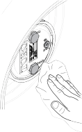
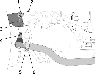
Clean the filter head and filter canister .
-
Remove the filter canister, and clean the mounting surface of the filter head.
-
Lubricate the gasket on the filter canister with clean fuel.
-
Install the filter canister by hand until the gasket contacts the mounting surface, then rotate it an additional 1/2 turn.
-
Tighten the drain valve at the bottom of the filter canister.
-
Start the engine and check for leaks.
-
Shut off the engine and remove the key.
-
Close and latch the hood.
Draining and Cleaning the Fuel Tank
Drain and clean the fuel tank if the fuel system becomes contaminated or if the machine is to be stored for an extended period.
Use clean fuel to flush out the tank.
-
Prepare the machine for maintenance.
-
Align a drain container under the drain valve at the bottom of the fuel tank.
-
Open the drain valve and allow the fuel to drain.
-
If needed, add clean fuel to the fuel tank to flush it out.
-
Close the drain valve.
Note: When you add fuel to the tank, check the drain valve for leaks.
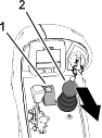
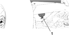
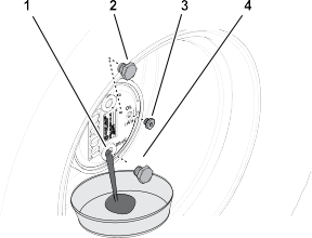
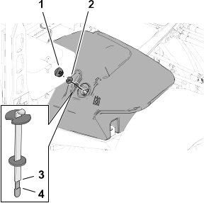
Cleaning the Fuel-Intake Screen
The fuel-intake tube, located inside the fuel tank, is equipped with a screen to help prevent debris from entering the fuel
system. Remove the fuel-intake tube and clean the screen as required.
-
Prepare the machine for maintenance.
-
Tilt the seat.
-
Remove the clamp that secures the hose to the fuel pick-up tube.
-
Remove the fuel pick-up tube and rubber bushing from the tank.
-
Clean the screen at the end of the fuel pick-up tube.
-
Insert the fuel pick-up tube and rubber bushing into the tank until the bushing is seated into the tank.
-
Assemble the hose onto the fuel pick-up tube and secure it with the clamp.
-
Lower and latch the seat.
Electrical System Maintenance
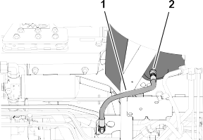
Disconnecting the Battery
|
Danger |
|
Battery electrolyte contains sulfuric acid, which is fatal if consumed and causes severe burns.
- Do not drink electrolyte and avoid contact with skin, eyes, or clothing.
- Wear safety glasses and rubber gloves.
- Fill the battery where clean water is always available for flushing the skin.
-
Prepare the machine for maintenance.
-
Open the battery-compartment cover.
-
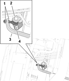
Disconnect the negative battery cable .
-
Slide the rubber boot off the positive battery-cable clamp, and disconnect the positive battery cable .
Connecting the Battery
-
Install the positive battery cable (red) to the positive (+) battery post.
-
Install the negative battery cable (black) to the negative (-) battery post.
-
Apply a coat of Grafo 112X (skin-over) grease, Toro Part No. 505-47 to the battery posts and battery-cable clamps.
-
Slide the rubber boot over the positive battery-cable clamp.
-
Close and latch the battery-compartment cover.
Charging the Battery
-
Disconnect the battery.
-
Connect a 3 to 4 A battery charger to the battery posts.
-
Charge the battery at a rate of 3 to 4 A for 4 to 8 hours.
-
When the battery is charged, disconnect the charger from the electrical outlet and battery posts.
-
Connect the battery.
Servicing the Battery
Note: Keep the terminals and the entire battery case clean because a dirty battery will discharge slowly.
-
Prepare the machine for maintenance.
-
Open the battery-compartment cover.
-
Check the condition of the battery.
Note: Replace a worn or damaged battery.
-
Disconnect the battery cables, and remove the battery from the machine.
-
Wash the entire battery case with a solution of sodium bicarbonate (baking soda) and water.
-
Rinse the case with clean water.
-
Assemble the battery to the machine and connect the battery cables.
-
Close and latch the battery-compartment cover.
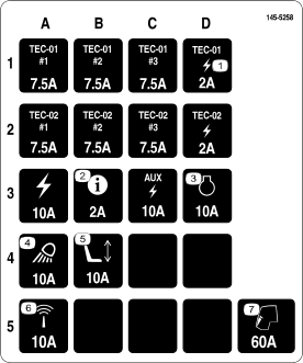
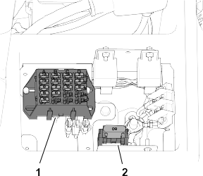
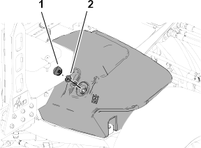
Replacing a Fuse
The fuse block is in the battery compartment.
-
Prepare the machine for maintenance.
-
Open the battery-compartment cover.
-
Replace the open fuse with the same fuse type and amperage rating.
G425167
- Fuse block
- Maxi fuse socket
G425168
-
Close and latch the battery-compartment cover.
Drive System Maintenance
Checking the Tire Pressure
|
Warning |
|
Low tire pressure decreases machine side hill stability. This could cause a rollover, which could result in death or serious
injury.
Do not under-inflate the tires.
Note: Maintain the recommended pressure in all tires to ensure a good quality of cut and proper machine performance.
-
Measure the air pressure in each tire. The correct air pressure in the tires is 83 to 103 kPa (12 to 15 psi).
-
If needed, add air to or remove air from the tires until you measure 83 to 103 kPa (12 to 15 psi).
Torquing the Wheel Nuts
|
Warning |
|
Failing to maintain proper torque of the wheel nuts could cause a wheel to come loose, which could result in death or serious
injury.
Torque the front and rear wheel nuts to 115 to 136 N∙m (85 to 100 ft-lb) after 1 to 4 hours of operation and again after 8 hours of operation. Torque the wheel nuts every 200
hours thereafter.
-
Prepare the machine for maintenance.
-
Torque the wheel nuts to 115 to 136 N∙m (85 to 100 ft-lb).
Note: The front wheel nuts are 1/2–20 UNF; the rear wheel nuts are M12 x 1.6-6H (metric).
Checking for End-Play in the Planetary Drives
|
Danger |
|
A machine on a jack may be unstable and slip off the jack, which could result in death or serious injury.
- Do not start the engine while the machine is on a jack.
- Always remove the key from the switch before getting off the machine.
- Block the tires when you are raising the machine with a jack.
- Support the machine with jack stands.
There should be no end-play in the planetary drives/drive wheels (i.e., the wheels should not move when you pull or push them
in a direction parallel to the axle).
-
Prepare the machine for maintenance.
-
Chock the rear wheels and raise the front of machine.
-
Support the front frame of the machine with jack stands.
-
Grasp a front drive wheel and push/pull it toward and away from the machine, noting any movement.
-
Repeat step 4 for the other drive wheel.
-
If either wheel moves, contact your authorized Toro distributor to have the planetary drive rebuilt.
Checking the Planetary Gear-Drive Lubricant
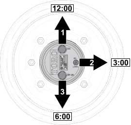
Lubricant Specification: high quality SAE 85W-140 gear oil
-
Park the machine on level surface, position the wheel so that the fill plug is at the 12 o'clock position, the check plug is at 3 o'clock position, and the drain plug is at the 6 o'clock position.
-
Remove the check plug at the 3 o’clock position.
Note: The oil level should be at the bottom of the check-plug hole .
-
If the oil level is low, remove the fill plug at the 12 o’clock position and add oil until it begins to flow out of the hole at the 3 o’clock position.
-
Check the O-ring for the plug(s) for wear or damage.
Note: Replace the O-ring(s) as needed.
-
Install the plug(s).
-
Repeat this procedure on the planetary gear assembly at the other side of the machine.
Changing the Planetary-Gear-Drive Oil
Lubricant specification: high quality SAE 85W-140 gear oil
Planetary and brake housing lubrication capacity: 0.65 L (22 fl oz)
Draining the Planetary-Gear-Drive
-
Park the machine on level surface, position the wheel so that the fill plug is at the 12 o'clock position, the check plug
is at 3 o'clock position, and the drain plug is at the 6 o'clock position.
-
Remove the fill plug at the 12 o’clock position and the check plug at the 3 o’clock position.
G425192
-
Drain-plug hole
-
Fill plug
-
Check plug
-
Drain plug
-
Place a drain pan under the planetary hub, remove the drain plug at the 6 o’clock position, and allow the oil to fully drain.
-
Check the O-rings for the fill, check, and drain plugs for wear or damage.
Note: Replace the O-ring(s) as needed.
-
Install the drain plug into the drain hole of the planetary housing.
-
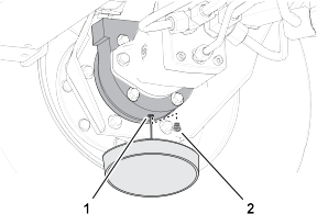
Place a drain pan under the brake housing, remove the drain plug, and allow the oil to fully drain.
G425193
-
Drain hole (brake housing)
-
Drain plug
-
Check the O-ring for the plug for wear or damage and install the drain plug into the brake housing.
Note: Replace the O-ring as needed.
Filling the Planetary-Gear-Drive with Lubricant
-
Through the fill-plug hole , slowly fill the planetary with 0.65 L (22 fl oz) of high quality SAE 85W-140 gear oil.
If the planetary fills before you add 0.65 L (22 fl oz) of oil, wait 1 hour or install the plug and move the machine approximately
3 m (10 ft) to distribute the oil through the brake system. Then, remove the plug and add the remaining oil.
-
Install the fill plug and the check plug.
-
Wipe clean the planetary and brake housings.
-
Drain and fill the planetary-gear-drive on the other side of the machine.
Inspecting the Rear Axle
-
Visually inspect the rear axle for leaks. Make all necessary repairs before operating.
Checking the Oil Level of the Rear Axle
Axle Oil Specification: SAE 85W-140 gear oil
-
Prepare the machine for maintenance.
-
Remove a check plug from the end of the axle housing.
-
Check the gear oil level in the axle through the check-plug hole.
Note: The gear-oil level is correct if the oil level is at the bottom of the check-plug hole.
-
If the gear-oil level low, remove the fill plug and add the specified gear oil to raise the oil level to the bottom of the check-plug hole.
-
Install the check plug.
-
If removed, install the fill plug.
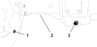
Changing the Oil in the Rear Axle
Rear Axle Oil Capacity: 2.4 L (80 fl oz)
-
Prepare the machine for maintenance.
-
Clean the area around the 3 drain plugs—1 at each bevel-gear case (outboard of the axle housings ) and 1 in the center-gear case .
-
Remove each drain plug and allow the oil to drain into a drain pan.
-
Remove the 2 axle housing check plugs and the fill plug to ease in draining of the oil.
-
Install the 3 drain plugs and the check plug at the axle housing with the breather fitting.
-
At the fill plug axle port, fill the axle with approximately 2.37 L (80 fl oz) of 85W-140 gear oil or until the oil level
is at the bottom of the hole.
-
Install the check plug and the fill plug.
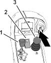
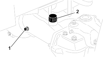
Inspecting the Reduction-Gear Case
-
Visually inspect the reduction-gear case for leaks. Make all necessary repairs before operating.
Checking the Lubricant in the Reduction-Gear Case
Reduction-Gear Case Oil Specification: SAE 85W-140 gear oil
-
Prepare the machine for maintenance.
-
Remove the check/fill plug from the left side of the reduction-gear case .
-
Check the O-ring for the plug is not worn or damaged.
-
Check the gear-case oil level.
Note: The gear-oil level is correct if the oil level is at the bottom of the check/fill-plug hole.
-
If the gear-oil level is low, add enough of the specified case oil to bring the level up to the bottom of the check/fill-plug
hole.
-
Install the check/fill plug.
Adjusting Maximum Mow-Ground Speed
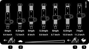
Adjusting the Mow Speed-Spacers
-
Prepare the machine for maintenance.
-
Use the Mow Speed-Spacer Table to determine the maximum ground speed when you mow, and the position of the short spacers that
limit mow-ground speed.
Note: Each short spacer adjusts the mowing speed by 0.8 km/h (0.5 mph).
-
Below the traction pedal, remove the stop bolt and flange locknut that secure the spacers to the mow-stop block.
G425372
-
Traction pedal
-
Mow-speed limiter
-
Stop bolt
-
Short spacers
-
Mow-stop block
-
Flange locknut
-
Position the long spacer above the mow-stop block.
-
Position the short spacers as you determined in step 2.
-
Secure the spacers to the mow-stop block with the stop bolt and flange locknut that you removed in step 3.
Note: You must install all 6 short spacers and the long spacer.
-
Set the mow speed in the InfoCenter.
Setting the Mow Speed in the InfoCenter
The mow speed setting in the InfoCenter is used by the TEC to adjust reel speed of the cutting units to the maximum mow-ground
speed.
-
In the InfoCenter, access the Main Menu.
-
In the Main Menu, press the middle button until the Settings option is highlighted, and press the right button.
-
In the Settings Menu, press the middle button until the Protected Menus option is highlighted, and press the right button.
-
In the Protected Menus screen, enter the PIN code.
-
In the Settings Menu, press the middle button until the Mow Speed option is highlighted, and press the right button.
-
In the Mow Speed screen, press the middle button or the right button until the mow speed shown in the display is the same as the maximum mow-ground
speed that you previously determined.
Note: The mow speed setting increases or decreases in 0.8 kph (0.5 mph) increments.
Note: The indicator light illuminates and Advisory #176 (Reel Speed Changed) displays.
-
Press the left button to exit the Settings Menu.
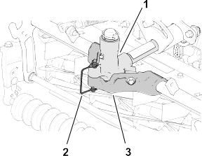
Adjusting the Traction Drive for Neutral
The machine must not move forward or backward when you release the traction pedal. If the machine moves, adjust the traction
drive for neutral.
-
Park the machine on a level surface, shut off the engine, position the speed control into the low range, and lower the cutting
units.
-
Press only the right brake pedal and engage the parking brake.
-
Jack up the left side of the machine until the left front tire is off the ground. Support the machine with jack stands to
prevent it from falling accidentally.
-
Start the engine and allow it run at low idle.
-
Adjust the jam nuts on the rod end to move the traction rod forward to eliminate forward creep or rearward to eliminate rearward
creep .
G425377
-
Jam nuts
-
Traction hub pivot
-
Traction rod
-
Rod end
-
When the wheel stops rotating, tighten the jam nuts to secure the adjustment.
-
Shut off the engine and remove the key.
-
Remove the jack stands and lower the machine to the ground.
-
Test drive the machine to ensure that it does not creep.
Checking the Rear-Wheel Alignment
-
Prepare the machine for maintenance.
-
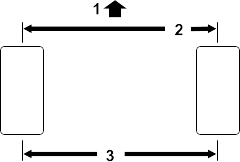
Measure the center-to-center distance (at axle height) at the front and rear of the steering tires.
Note: The front measurement must be 3 mm (1/8 inch) less than the rear measurement.
G416236
-
Front of the traction unit
-
3 mm (1/8 inch) less than the rear of the tire
-
Center-to-center distance
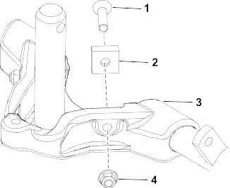
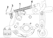
Adjusting the Rear-Wheel Toe-In
-
At the rear axle, remove the cotter pin and the slotted nut from either tie-rod end.
G425379
-
Slotted nut
-
Cotter pin
-
Axle case-steering arm
-
Tie-rod end
-
Clamp
-
Nut and bolt
-
Separate the tie-rod end from the axle case-steering arm.
-
Loosen the clamps at both ends of the tie rods.
-
Rotate the detached ball joint inward or outward a complete revolution.
-
Tighten the clamp at the detached end of the tie rod.
-
Rotate the entire tie-rod assembly the same direction (inward or outward) a complete revolution.
-
Tighten the clamp at the connected end of the tie rod.
-
Assemble the tie-rod end to the axle case-steering arm with the slotted nut.
-
Measure the toe-in.
-
If needed, remove the slotted nut and repeat steps 2 through 9.
-
When the difference between the front and rear measurements are 3 mm (1/8 inch) less, tighten the slotted nut and install
a new cotter pin.
Cooling System Maintenance
Coolant Specifications
The coolant reservoir is filled at the factory with a 50/50 solution of water and ethylene glycol base extended-life coolant.
Use only commercially available coolants that meet the specifications listed in the Extended Life Coolant Standards Table.
Do not use conventional (green) inorganic-acid technology (IAT) coolant in your machine. Do not mix conventional coolant with
extended-life coolant.
Coolant Type Table
|
Extended-life antifreeze
|
Organic-acid technology (OAT)
|
Do not rely on the color of the coolant to identify the difference between conventional (green) inorganic-acid technology
(IAT) coolant and extended-life coolant.
Coolant manufacturers may dye extended-life coolant in one of the following colors: red, pink, orange, yellow, blue, teal,
violet, and green. Use coolant that meets the specifications in the Extended Life Coolant Standards Table.
|
Extended Life Coolant Standards
|
D3306 and D4985
|
J1034, J814, and 1941
|
Coolant concentration should be a 50/50 mixture of coolant to water.
- Preferred: When mixing coolant from a concentrate, mix it with distilled water.
- Preferred option: If distilled water is not available, use a pre-mix coolant instead of a concentrate.
- Minimum requirement: If distilled water and pre-mix coolant are not available, mix concentrated coolant with clean drinkable water.
Cooling system capacity
Approximately 12.3 L (13 US qt)
Checking the Coolant Level
|
Caution |
|
If the engine has been running, the pressurized, hot coolant can escape, which could result in minor or moderate injury.
- Do not open the radiator cap when the engine is running.
- Use a rag when opening the radiator cap, and open the cap slowly to allow steam to escape.
-
Prepare the machine for maintenance.
-
Open the hood, and wait for the engine to cool..
-
Carefully remove the radiator cap .
-
Check the coolant level in the radiator.
Note: The coolant level is correct if it is to the top of the filler neck of the radiator.
-
Check the coolant level in the expansion tank.
Note: The coolant level is correct if it is to the Full mark of the expansion tank.
-
If the coolant is low, add the specified coolant to the radiator, expansion tank, or both.
-
Install the radiator cap and the expansion-tank cap .
-
Close and latch the hood.
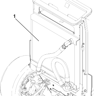
Servicing the Engine Cooling System
-
Prepare the machine for maintenance.
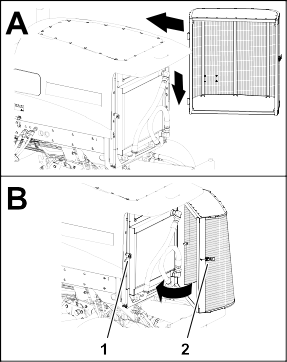
-
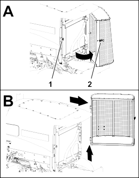
Unlatch and open the rear screen.
G425401
-
Latch keeper
-
Rear screen latch
-
Clean both sides of the screen.
-
Lift the screen off the hinge pins, and remove the screen from the machine.
-
Open the hood.
-
Clean both sides of the oil cooler/radiator area thoroughly with compressed air. Start from the front and blow the debris
out toward the back. Then clean from the back side and blow toward the front. Repeat the procedure several times until all
chaff and debris is removed.
Cleaning the oil cooler/radiator with water may promote premature corrosion damage to components and compact debris.
G425402
-
Oil cooler/radiator
-
Close and latch the hood.
-
Assemble the screen onto the hinge pins.
G425403
-
Latch keeper
-
Rear screen latch
-
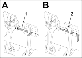
Close and latch the screen.
Brake Maintenance
Adjusting the Service Brakes
Adjust the service brakes when there is more than 13 mm (1/2 inch) of free travel of the brake pedal, or if the brakes slip.
Free travel is the distance the brake pedal moves before you feel braking-pedal resistance.
-
Prepare the machine for maintenance.
-
Disengage the pedal-locking latch between the brake pedals so that both pedals work independently of each other.
G425404
-
Brake pedals locked
-
Brake pedals unlocked
-
Loosen the front jam nut on the threaded end of the brake cable.
G425405
G425406
-
Left brake cable
-
Right brake cable
-
Jam nuts
-
Front of the machine
-
To reduce free travel of the brake pedals, tighten the rear jam nut to move the cable rearward until the brake pedals have
0 to 13 mm (0 to 1/2 inch) of free travel.
Note: Ensure that there is no brake-cable tension when the pedal is released.
-
Tighten the front jam nut after the brakes are adjusted correctly.
-
If needed, repeat steps 3 through 5 at the other brake cable.
Belt Maintenance
Tensioning the Alternator Belt
-
Prepare the machine for maintenance.
-
Open the hood.
-
Check the condition of the alternator belt.
Note: Replace a worn or damaged belt.
-
Check the tension of the alternator belt by pressing it midway between the pulleys.
Note: With 45 N (10 lb) of force, the belt should deflect 10 mm (3/8 inch).
-
If the deflection is incorrect, complete the following procedure to tension the belt:
-
Loosen the alternator mounting bolts .
-
Increase or decrease the alternator-belt tension, and tighten the mounting bolts.
-
Check the deflection of the belt again to ensure that the tension is correct.
-
Close and latch the hood.
Hydraulic System Maintenance
Inspecting the Hydraulic Lines and Hoses
-
Inspect the hydraulic lines and hoses for leaks, kinked lines, loose mounting supports, wear, loose fittings, weather deterioration,
and chemical deterioration.
Note: Make all necessary repairs before operating.
Hydraulic Fluid Specifications
The reservoir is filled at the factory with high-quality hydraulic fluid. Check the level of the hydraulic fluid before you
first start the engine and daily thereafter.
Recommended hydraulic fluid: Toro PX Extended Life Hydraulic Fluid; available in 19 L (5 US gallon) pails or 208 L (55 US gallon) drums.
Note: A machine using the recommended replacement fluid requires less frequent fluid and filter changes.
Alternative hydraulic fluids: If Toro PX Extended Life Hydraulic Fluid is not available, you may use another conventional, petroleum-based hydraulic fluid having
specifications that fall within the listed range for all the following material properties and that it meets industry standards.
Do not use synthetic fluid. Consult with your lubricant distributor to identify a satisfactory product.
Note: Toro does not assume responsibility for damage caused by improper substitutions, so use products only from reputable manufacturers
who will stand behind their recommendation.
High Viscosity Index/Low Pour Point Anti-wear Hydraulic Fluid, ISO VG 46
| Material Properties: |
|
| |
Viscosity, ASTM D445 |
cSt @ 40°C (104°F) 44 to 48 |
| |
Viscosity Index ASTM D2270 |
140 or higher |
| |
Pour Point, ASTM D97 |
-37°C to -45°C (-34°F to -49°F) |
| |
Industry Specifications: |
Eaton Vickers 694 (I-286-S, M-2950-S/35VQ25 or M-2952-S) |
Note: Many hydraulic fluids are almost colorless, making it difficult to spot leaks. A red dye additive for the hydraulic fluid
is available in 20 ml (0.67 fl oz) bottles. A bottle is sufficient for 15 to 22 L (4 to 6 US gallons) of hydraulic fluid.
Order Part No. 44-2500 from your authorized Toro distributor.
Toro Premium Synthetic Biodegradable Hydraulic Fluid is the only synthetic biodegradable fluid approved by Toro. This fluid is compatible with the elastomers used in Toro hydraulic systems and is suitable for a wide-range of temperature conditions. This fluid is compatible with conventional
mineral oils, but for maximum biodegradability and performance, the hydraulic system should be thoroughly flushed of conventional
fluid. The oil is available in 19 L (5 US gallon) pails or 208 L (55 US gallon) drums from your authorized Toro distributor.
Hydraulic tank capacity
28.4 L (7.5 US gallons)
Checking the Hydraulic-Fluid Level
The reservoir is filled at the factory with high-quality hydraulic fluid.
-
Prepare the machine for maintenance.
-
Clean the area around the filler neck and cap of the hydraulic tank.
-
Remove the hydraulic-tank cap from the tank.
-
Remove the dipstick from the filler neck and wipe it with a clean rag.
-
Insert the dipstick into the filler neck; then remove it and check the fluid level.
The correct hydraulic-fluid level is between the full mark and the add mark on the dipstick.
-
If the level is low, add the specified hydraulic fluid to raise the fluid level to the full mark.
-
Install the dipstick and hydraulic-tank cap to the tank.
Replacing the Hydraulic Filters
Use the following Toro hydraulic filters:
|
Return filter
|
94-2621
|
Below the right frame channel.
|
|
Charge filter
|
75-1310
|
Under the seat plate.
|
Using another type of filter may void the warranty on some components.
|
Changing the Charge Filter
-
Prepare the machine for maintenance.
-
Tilt the seat.
-
Clean the area around the charge filter and filter head .
-
Align a drain pan under the filter and remove the filter.
-
Wipe the filter mounting filter surface of the filter head with a clean rag.
-
Lubricate the new filter gasket and fill the filter with the specified hydraulic fluid.
-
Thread the filter onto the filter head until the gasket contacts the mounting plate, then tighten the filter an additional
1/2 turn.
Changing the Return Filter
-
Clean the area around the return filter and filter head .
-
Align a drain pan under the return filter and remove the filter.
-
Wipe the filter mounting filter surface of the filter head with a clean rag.
-
Lubricate the new filter gasket, fill the filter with the specified hydraulic fluid, and then drain the filter.
-
Thread the filter onto the filter head until the gasket contacts the mounting plate, then tighten the filter an additional
1/2 turn.
Purging Air from the Hydraulic System
-
Start the engine and let it run for about 2 minutes to purge air from the system.
-
Check around the filters and filter heads for hydraulic leaks.
Note: Repair any hydraulic leaks.
-
Shut off the engine and remove the key.
-
Lower the seat.
Changing the Hydraulic Fluid
Draining the Hydraulic Fluid
If the fluid becomes contaminated, contact your local authorized Toro distributor, because the system must be flushed. Contaminated fluid looks milky or black when compared to clean fluid.
Drain Pan Capacity: 30 L (8 US gallons) or more
-
Prepare the machine for maintenance.
-
Open the hood.
-
Align the drain pan under the hydraulic tank.
-
Disconnect the case-return hose from the straight fitting at the bottom of the tank, and drain hydraulic fluid.
-
When the hydraulic fluid stops draining, assemble the case-return hose to the tank fitting.
-
Torque the hose fitting to 50 to 63 N∙m (37 to 47 ft-lb).
Filling the Hydraulic Tank
-
Fill the reservoir with the specified hydraulic fluid.
Use only the hydraulic fluids specified. Other fluids could cause system damage.
-
Install the dipstick and hydraulic-tank cap to the tank.
-
Start the engine and operate all the hydraulic controls to distribute hydraulic fluid throughout the system.
-
Check for hydraulic leaks, shut off the engine, and remove the key.
Note: Repair all hydraulic leaks.
-
Close and latch the hood.
-
Check the fluid level.
Note: If needed, add enough to raise the level to the full mark on the dipstick. Do not overfill the hydraulic tank.
Cutting Unit Maintenance
Backlapping the Cutting Units
|
Warning |
|
Contact with the cutting units or other moving parts could result in death or serious injury.
- Keep your fingers, hands, and clothing away from the cutting units and other moving parts.
- Never attempt to turn the cutting units by hand or foot while the engine is running.
Note: Additional instructions and procedures on backlapping are available in the Toro Sharpening Reel and Rotary Mowers Manual, Form No. 80-300SL.
Preparing the Machine
-
Park the machine on a level surface, lower the cutting units, engage the parking brake, shut off the engine, and move the
PTO switch to the Disengage position.
-
Open the hood.
-
Make initial reel-to-bedknife adjustments appropriate for backlapping on all cutting units which are to be backlapped; refer
to the cutting unit Operator's Manual.
-
Rotate the front, rear, or both backlap levers to the R (backlap) position.
G425459
-
Backlap lever (front cutting units 4, 1, and 5)
-
Backlap lever (rear cutting units 2 and 3)
-
Reverse rotation (backlap)
Lapping the Reels and Bedknife
|
Warning |
|
Changing the engine speed while backlapping may cause the cutting units to stall, which could result in death or serious injury.
- Never change the engine speed while backlapping.
- Backlap only at idle engine speed.
Note: When backlapping, the front units all operate together, and the rear units operate together.
-
Ensure that the traction pedal is in the neutral position and the parking brake is engaged.
-
Start the engine and run it at low-idle speed.
-
Rotate the lever for the mow-speed limiter forward to the Mow position.
-
Press the PTO switch to the Engage position.
-
Move the lower mow/raise control lever forward.
Note: The reels you set for backlapping run backward.
-
Apply lapping compound to the reels with a long-handled brush.
|
Danger |
|
Contacting the cutting units when they are moving will result in death or serious injury.
- Do not use a short-handled brush.
- To avoid personal injury, ensure that you are clear of the cutting units before proceeding.
-
If the reels stall or become erratic while backlapping, increase the throttle speed until the reel stabilizes.
-
If you need to make an adjustment to the cutting units while backlapping, perform the following steps:
-
Move the lower mow/raise control lever rearward.
Note: The cutting units shut off, but do not raise.
-
Press the PTO switch to the Disengage position.
-
Shut off the engine and remove the key.
-
Adjust the cutting units.
-
Repeat steps 2 through 7.
-
Repeat step 6 for all cutting units that you want to backlap.
Finishing Backlapping
If you do not return the backlap switch to the Off position after backlapping, the cutting units will not raise or function properly.
-
Shut off the engine and remove the key.
-
Wash all lapping compound off of the cutting units.
-
Adjust the cutting unit reel-to-bedknife as needed.
-
Rotate the backlap levers to the F (mow) position.
G425519
-
Backlap lever (front cutting units 4, 1, and 5)
-
Backlap lever (rear cutting units 2 and 3)
-
Forward rotation (mow)
-
For a better cutting edge, run a file across the front face of the bedknife after lapping.
Note: This removes any burrs or rough edges that may have built up on the cutting edge.
-
Close and latch the hood.
Chassis Maintenance
Inspecting the Seat Belt
-
Inspect the seat belt for wear, cuts, and other damage. Replace the seat belt(s) if any component does not operate properly.
-
Clean the seat belt as necessary.
Cleaning
Washing the Machine
-
Wash the machine as needed using water alone or with a mild detergent. You may use a rag when washing the machine.
- Do not use brackish or reclaimed water to clean the machine.
- Do not use power-washing equipment to wash the machine. Power-washing equipment may damage the electrical system, loosen important
decals, or wash away necessary grease at friction points. Avoid excessive use of water near the control panel, engine, and
battery.
- Do not wash the machine with the engine running. Washing the machine with the engine running may result in internal engine
damage.
Storing the Machine
-
Park the machine on a level surface, lower the cutting units, engage the parking brake, shut off the engine, and remove the
key.
-
Thoroughly clean the traction unit, cutting units, and the engine.
-
Check the tire pressure.
-
Check all fasteners for looseness; tighten them as necessary.
-
Grease or oil all grease fittings and pivot points. Wipe up any excess lubricant.
-
Lightly sand and use touch-up paint on painted areas that are scratched, chipped, or rusted. Repair any dents in the metal
body.
-
Service the battery and cables as follows:
-
Remove the battery terminals from the battery posts.
-
Clean the battery, terminals, and posts with a wire brush and baking-soda solution.
-
Coat the cable terminals and battery posts with Grafo 112X skin-over grease (Toro Part No. 505-47) or petroleum jelly to prevent corrosion.
-
Slowly charge the battery every 60 days for 24 hours to prevent lead sulfation of the battery.
-
Prepare the engine as follows:
-
Drain the engine oil from the oil pan and install the drain plug.
-
Remove and discard the oil filter. Install a new oil filter.
-
Fill the engine with specified motor oil.
-
Start the engine and run it at idle speed for approximately 2 minutes.
-
Shut off the engine and remove the key.
-
Flush the fuel tank with fresh, clean fuel.
-
Secure all the fuel-system fittings.
-
Thoroughly clean and service the air-cleaner assembly.
-
Seal the air-cleaner inlet and the exhaust outlet with weatherproof tape.
-
Check the antifreeze protection and add a 50/50 solution of water and ethylene glycol antifreeze as needed for the expected
minimum temperature in your area.
Storing the Battery
If you are storing the machine for more than 30 days, remove the battery and charge it fully. Either store it on the shelf
or on the machine. Leave the cables disconnected if they are stored on the machine. Store the battery in a cool atmosphere
to avoid quick deterioration of the charge in the battery. To prevent the battery from freezing, ensure that it is fully charged.
The specific gravity of a fully charged battery is 1.265 to 1.299.