Installation
Note: Determine the left and right sides of the machine from the normal operating position.
Preparing the Machine
-
Park the machine on a level surface.
-
Engage the parking brake.
-
Shut off the machine and remove the key.
-
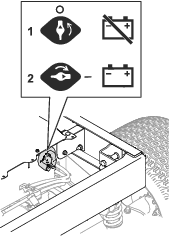
Turn the battery-disconnect switch to the OFF position (Figure 1).
-
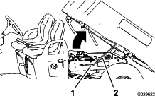
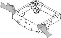
Lift the lever on either side of the cargo bed and lift the bed up (Figure 2).
-
Pull the prop rod into the detent slot to secure the bed (Figure 3).
Warning
A raised bed could fall and injure persons that are working beneath it.
-
Always use the prop rod to hold the bed up before working under the bed.
-
Remove any load material from the bed before raising it.
-
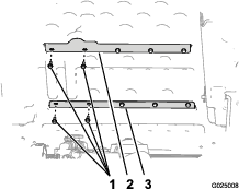
-
Remove the 4 flange nuts securing the latch-rod brackets to the underside of the bed (Figure 4).
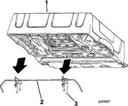
-
Remove and retain the latch rod and latches.
Installing the Bed-Lift Brackets
Parts needed for this procedure:
| Outboard-lift bracket (short flanges) | 1 |
| Inboard-lift bracket (long flanges) | 1 |
| Hex-head bolt (5/16 x 5-1/2 inches) | 1 |
| Flange nut (5/16 inch) | 1 |
Perform the bed bracket installation at the bottom side of the bed.
-
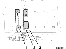
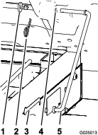
Remove the 2 left-most bolts (5/16 x 3/4 inch) that secure upper-bed brace to the bed (Figure 5).
-
Remove the 2 left-most bolts (5/16 x 3/4 inch) that secure lower-bed brace to the bed (Figure 5).
Note: Retain the 4 bolts for installation.
-
Align the left outboard-lift bracket (the bracket with the short flanges) to the outboard holes in the upper- and lower-bed braces (Figure 6).
-
Secure the outboard lift bracket to the bed using the 2 bolts that you removed in step 1, and hand-tighten the bolts (Figure 6).
-
Align the inboard-lift bracket (the bracket with the long flanges) to the inboard holes in the upper- and lower-bed braces (Figure 6).
-
Secure the inboard-lift bracket to the bed with the 2 bolts that you removed in step 2, and hand-tighten the bolts (Figure 6).
-
Insert the hex-head bolt (5/16 x 5-1/2 inches) through the hole (8 mm or 5/16 inch) in the inboard-lift bracket (long flanges), bed structure, and the outboard bed-lift bracket (short flanges) as shown in Figure 7.
-
Secure the bolt with the flange nut (5/16 inch) hand-tight (Figure 7).
Installing the Switch
Parts needed for this procedure:
| Switch | 1 |
| Hex washer head screw (#10 x 3/4 inch) | 2 |
| Relay | 2 |
-
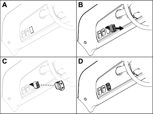
Cut out the opening in the dashboard decal for the switch.
-
Install the switch connector through the opening in the dashboard.
-
Route the switch to the switch connector.
-
Ensure that the switch is oriented properly and install the switch into the dash.
Note: The switch should snap and lock into position.
-
Secure the relays to the back of the dash with 2 hex washer head screws (#10 x 3/4 inch).
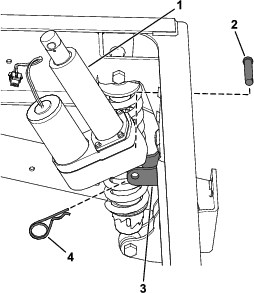
Installing the Lift Actuator
Parts needed for this procedure:
| Lift actuator | 1 |
| Clevis pin (3-1/2 inches) | 1 |
| Clevis pin (2-1/4 inches) | 1 |
| Hairpin | 2 |
| Hex-head bolt (1/2 x 5-1/2 inches) | 1 |
| Locknut (1/2 inch) | 1 |
-
Align the hole in the lower-mount point for the lift actuator with the holes in the chassis-mount brackets (Figure 10).
-
Secure the lift actuator to the chassis-mount brackets with the clevis pin (2-1/4 inches) and hairpin (Figure 10).
-
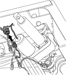
Connect the 2-socket electrical connector of the rear wire harness of the machine to the 2-pin connector of the lift actuator (Figure 11).
Note: The 2-socket electrical connector of the rear wire harness is located on the back of the battery box, above the battery-disconnect switch.
-
Turn the battery-disconnect switch to the ON position (Figure 1).
-
Press the bed-lift switch up to extend the actuator (Figure 8).
-
Press the up paddle on the bed-lift switch to extend the lift-actuator rod until the hole in the rod is aligned with the holes in the inboard and outboard-lift brackets (Figure 12).
-
Secure the lift-actuator rod to the lift brackets with the clevis pin (3-1/2 inches) and hairpin (Figure 12).
-
Tighten the 4 bolts (5/16 x 3/4 inch) that secure the inboard and outboard-lift brackets to the bed (Figure 6) to 15 to 16.6 N∙m (133 to 147 in-lb).
-
Align the hex-head bolt (1/2 x 5-1/2 inches) through the remaining 12.7 mm (1/2 inch) holes in the inboard and outboard-lift brackets (Figure 12) and secure it with a locknut (1/2 inch) until the nut is snug.
-
Tighten the flange nut that secures the bolt (5/16 inch) until it is snug (Figure 7).
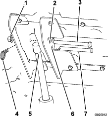
Removing the Prop Rod
Warning
A raised bed could fall and injure persons that are working beneath it.
-
Always use the prop rod to hold the bed up before working under the bed.
-
Remove any load material from the bed before raising it.
-
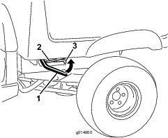
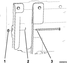
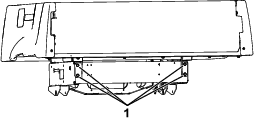
Remove the hairpin and washer that secure the prop rod to the bottom of the bed (Figure 13).
-
Slide the prop rod forward to remove it from the bracket on the frame (Figure 13).
Note: Retain the prop rod components for future use.
Note: If the electric box lift is ever removed, install the prop rod and latch rod again, using the existing fasteners and the prop-rod bracket.
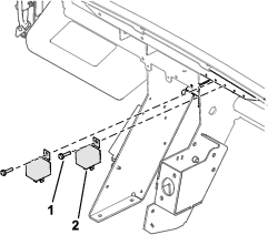
Installing the Foam Pads
Parts needed for this procedure:
| Foam pad | 2 |
-
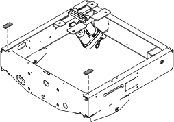
Clean the 2 areas of the frame (Figure 14) so that the adhesive on the foam pads adhere properly to the frame.
-
Remove the backing from the foam pads and adhere them as shown in Figure 15.
-
Fully lower the cargo bed and ensure that the cargo bed makes contact with the foam pads.
-
If the cargo bed does not make contact with the foam pads in both locations, loosen the 4 cargo bed hinge bolts (Figure 16).
Once the cargo bed makes contact with the foam pads, torque the 4 cargo bed hinge bolts to 37 to 44 N∙m (27 to 33 ft-lb).
Operation
Warning
Driving the machine with the cargo bed raised could cause the machine to tip or roll easier. You could damage the structure of the cargo bed if you operate the machine with the bed raised.
-
Operate the machine when the cargo bed is down.
-
After emptying the cargo bed, lower it.
Warning
The weight of the bed may be heavy. Hands or other body parts could be crushed.
Keep your hands and other body parts clear when lowering the bed.
Important: When you hear a ratcheting sound, the bed lift is completely extended or retracted. Do not continue pressing the switch.
Raising the Bed
-
Turn the key switch to the ON position.
-
Push the top of the switch to raise the bed.
Lowering the Bed
Push the bottom of the switch to lower the bed.
Note: The actuator may cause slight deformation to the bed after it is fully lowered and before the actuator clutch engages. Release the switch when you hear a ratcheting noise.