Installation
Note: Determine the left and right sides of the machine from the normal operating position.
Preparing the Machine
-
Park the machine on a level surface.
-
Disengage the blade-control switch.
-
Move the motion-control levers outward to the NEUTRAL-LOCK position.
-
Engage the parking brake.
-
Shut off the engine and remove the key.
-
Disconnect the negative battery cable.
-
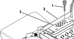
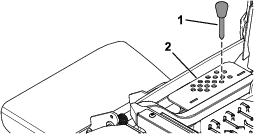
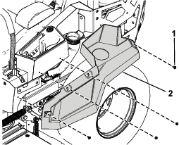
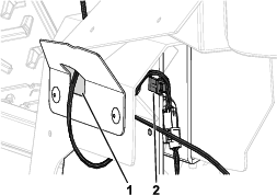
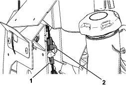
Push the deck-lift pedal fully forward to lock the mower deck in the TRANSPORT position (Figure 1).
-
Support the mower deck using 4x4 blocks of wood.
-
Remove the height-of-cut pin from the height-of-cut bracket (Figure 2).
Removing the Left Side Pod and Fuel-Tank Cap
-
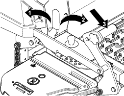
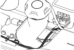
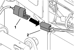
Remove the fuel-tank cap from the left side pod (Figure 3).
Retain the fuel-tank cap for later installation.
-
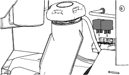
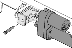
Remove the 4 shoulder screws securing the left side pod and remove the left side pod (Figure 4).
Retain the left side pod and 4 shoulder screws for later installation.
-
Install the fuel-tank cap (Figure 3).
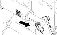
Removing the Existing Left Motion-Control Lever
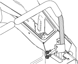
Remove the 2 flange-head bolts (3/8 x 1 inch) securing the existing left motion-control lever and remove the left motion-control lever (Figure 5).
Retain the 2 flange-head bolts (3/8 x 1 inch) for later installation.
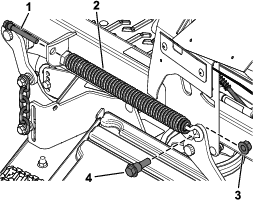
Removing the Deck-Lift Spring
Installing the New Left Motion-Control Lever
Parts needed for this procedure:
| Left motion-control lever | 1 |
-
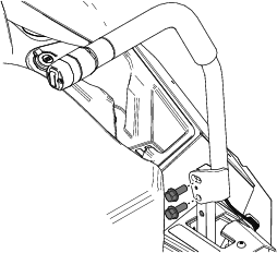
Secure the new left motion-control lever using the previously removed 2 flange-head bolts (3/8 x 1 inch) as shown in Figure 7.
-
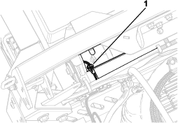
Route the wire harness on the motion-control lever through the hole in the left cover plate (Figure 8).
-
Secure the wire harness to the notch in the left motion-control plate (Figure 8).
Drilling the Frame
Parts needed for this procedure:
| Drilling template | 1 |
-
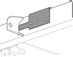
Install the drilling template onto the frame tube. Ensure the template is flush to the spring bracket.
Warning
Using a drill without proper eye protection may allow debris to enter the eye, causing injury.
When drilling, always wear eye protection.
-
Drill holes into the frame using a Letter X drill bit.
Important: Do not drill completely through one side. Drill from one side and then finish drilling from the other side.
-
Remove the drilling template from the frame tube.
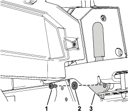
Installing the Actuator Brackets
Parts needed for this procedure:
| Button-head cap screws | 3 |
| Locknuts | 2 |
| Bracket | 1 |
| Actuator pivot pin | 1 |
-
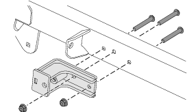
Install the bracket with 3 button-head cap screws and 2 locknuts.
-
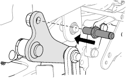
Install the actuator pivot pin.
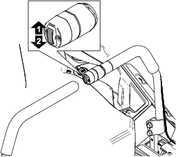
Routing the Wire Harness and Installing the Relays
Parts needed for this procedure:
| Deck lift wire harness | 1 |
| Push-mount fastener | 1 |
| Relay | 2 |
| Taptite screw | 1 |
-
Install the front push-mount fastener into the parking-brake lever bracket (Figure 12).
Note: The rear push-mount fastener is already installed.
-
Route the wire harness (Figure 13) along the left side of the frame, through the push-mount fastener you installed in step 1.

-
Install the second push-mount fastener into the rear fuel-tank bracket (Figure 14).
-
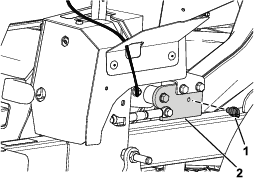
Secure the wire harness near the relays using the taptite screw (Figure 15).
-
Install the 2 relays (Figure 16).
Install the Left Side Pod and Fuel-Tank Cap
Connecting the Wire Harness
-
Connect the kit wire harness to the machine wire harness connector labeled .
-
Connect the kit wire harness connector to the new left motion-control lever connector (Figure 17).
-
Connect the kit wire harness to the actuator.
-
Pull the boot cover off the positive battery terminal.
-
Remove the nut from the positive battery terminal and install the kit wire harness positive terminal ring onto the bolt (Figure 18).
-
Secure the positive terminal ring using the previously removed nut (Figure 18).
-
Install the boot cover over the positive battery terminal.
-
Remove the nut from the negative battery terminal and install the kit wire harness negative terminal ring onto the bolt (Figure 18).
-
Secure the negative terminal ring using the previously removed nut (Figure 18).
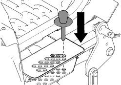
Installing the Actuator
Parts needed for this procedure:
| Actuator | 1 |
| Pin clip | 1 |
| Shoulder screw | 1 |
-
Plug the actuator wire harness into the deck lift wire harness.
-
Install the actuator.
Note: If the actuator does not line up with the pin, power up the actuator and extend or retract as needed.
-
Secure the actuator to the rear deck-lift arm using the pin clip.
-
Rotate the actuator upward and align the actuator with the hole in the outer actuator bracket.
If the holes do not align, turn the machine on, and carefully press the deck-lift switch on the motion-control lever up or down until the holes align.
Removing the Transport Lock
-
Push the deck-lift switch upward until you hear a ratcheting sound or clicking sound from the actuator.
-
Turn off the machine.
-
Remove the bolt, washer, and transport lock (Figure 22).
Checking the Mower Deck Height of Cut and Rake
Refer to the Adjusting the Side-to-Side Leveling and the Blade Slope procedure in the Operator's Manual.
Operation
Machine Transport with Electric Deck Lift
-
Push up on the deck-lift switch until the deck is completely raised.
-
Insert the height-of-cut pin into the 140 mm (5-1/2 inches) height-of-cut position of the bracket.
-
Push down on the deck-lift switch until the height-of-cut linage slightly contacts the height-of-cut pin.
Important: Transporting the machine without the deck resting on the height-of-cut pin will cause unnecessary damage to the deck lift actuator.
Adjusting the Height of Cut
-
Push up on the deck-lift switch.
-
Select a hole in the height-of-cut bracket corresponding to the height of cut desired, and insert the pin.
-
Push down on the deck-lift switch until the height-of-cut linkage slightly contacts the height-of-cut pin.
Note: Too much contact between the height-of-cut linkage and height-of-cut pin can negatively affect the mower deck height of cut and leveling.