| Maintenance Service Interval | Maintenance Procedure |
|---|---|
| Before each use or daily |
|
Introduction
This rotary-blade, riding lawn mower is intended to be used by professional, hired operators. It is designed primarily for cutting grass on well-maintained lawns on residential or commercial properties. Using this product for purposes other than its intended use could prove dangerous to you and bystanders.
Read this information carefully to learn how to operate and maintain your product properly and to avoid injury and product damage. You are responsible for operating the product properly and safely.
Visit www.Toro.com for product safety and operation training materials, accessory information, help finding a dealer, or to register your product.
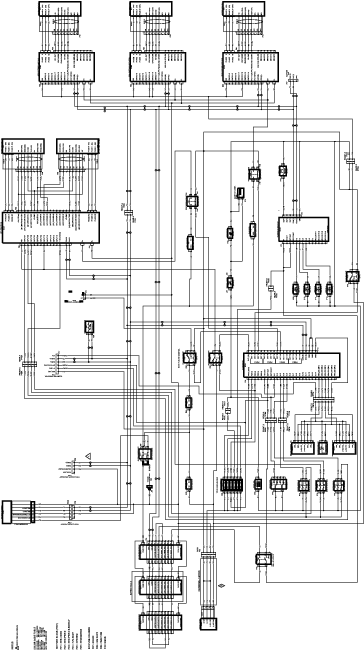
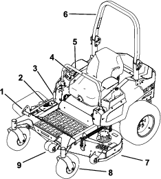
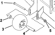
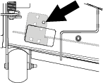
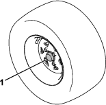
Whenever you need service, genuine Toro parts, or additional information, contact an Authorized Service Dealer or Toro Customer Service and have the model and serial numbers of your product ready. Figure 1 identifies the location of the model and serial numbers on the product. Write the numbers in the space provided.
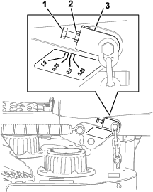
Important: With your mobile device, you can scan the QR code on the serial number decal (if equipped) to access warranty, parts, and other product information.
Warning
CALIFORNIA
Proposition 65 Warning
The power cord on this product contains lead, a chemical known to the State of California to cause birth defects or other reproductive harm. Wash hands after handling.
Battery posts, terminals, and related accessories contain lead and lead compounds, chemicals known to the State of California to cause cancer and reproductive harm. Wash hands after handling.
Use of this product may cause exposure to chemicals known to the State of California to cause cancer, birth defects, or other reproductive harm.
Safety
General Machine Safety Warnings
 WARNING—Read all safety warnings, instructions, illustrations
and specifications provided with this machine.
WARNING—Read all safety warnings, instructions, illustrations
and specifications provided with this machine.
Failure to follow the warnings and instructions may result in electric shock, fire and/or serious injury.
The term “machine” in all of the warnings listed below refers to your mains-operated (corded) machine or battery-operated (cordless) machine.
-
Work area safety
-
Keep work area clean and well lit.Cluttered or dark areas invite accidents.
-
Do not operate the machine in explosive atmospheres, such as in the presence of flammable liquids, gasses, or dust.The machine creates sparks, which may ignite the dust or fumes.
-
Keep children and bystanders away while operating the machine.Distractions can cause you to lose control.
-
-
Electrical safety
-
Machine plugs must match the outlet. Never modify the plug in any way. Do not use any adapter plugs with an earthed (grounded) machine.Unmodified plugs and matching outlets will reduce risk of electric shock.
-
Avoid body contact with earthed or grounded surfaces, such as pipes, radiators, ranges, and refrigerators.There is an increased risk of electric shock if your body is earthed or grounded.
-
Do not expose the machine to rain or wet conditions.Water entering a machine will increase the risk of electric shock.
-
Do not abuse the cord. Never use the cord for carrying, pulling or unplugging the machine. Keep cord away from heat, oil, sharp edges, or moving parts.Damaged or entangled cords increase the risk of electric shock.
-
When operating the machine outdoors, use an extension cord suitable for outdoor use.Use of a cord suitable for outdoor use reduces the risk of electric shock.
-
If operating the machine in a damp location is unavoidable, use a residual current device (RCD) protected supply.Use of an RCD reduces the risk of electric shock.
-
-
Personal safety
-
Stay alert, watch what you are doing, and use common sense when operating the machine. Do not use the machine while you are tired or under the influence of drugs, alcohol, or medication.A moment of inattention while operating the machine may result in serious personal injury.
-
Use personal protective equipment. Always wear eye protection.Protective equipment such as a dust mask, non-skid safety shoes, or hearing protection used for appropriate conditions will reduce personal injuries.
-
Prevent unintentional starting. Ensure the switch is in the off-position before connecting to power source and/or battery pack.Energising a machine that has the switch on invites accidents.
-
Remove any adjusting key or wrench before turning the machine on.A wrench or a key left attached to a rotating part of the machine may result in personal injury.
-
Do not overreach. Keep proper footing and balance at all times.This enables better control of the machine in unexpected situations.
-
Dress properly. Do not wear loose clothing or jewelry. Keep your hair and clothing away from moving parts.Loose clothes, jewelry or long hair can be caught in moving parts.
-
If devices are provided for the connection of dust extraction and collection facilities, ensure these are connected and properly used.Use of dust collection can reduce dust-related hazards.
-
Do not let familiarity gained from frequent use of the machine allow you to become complacent and ignore machine safety principles.A careless action can cause severe injury within a fraction of a second.
-
-
Machine use and care
-
Do not force the machine. Use the correct machine for your application.The correct machine will do the job better and safer at the rate for which it was designed.
-
Do not use the machine if the switch does not turn it on and off.Any machine that cannot be controlled with the switch is dangerous and must be repaired.
-
Disconnect the plug from the power source and/or remove the battery pack, if detachable, from the machine before making any adjustments, changing accessories, or storing the machine.Such preventive safety measures reduce the risk of starting the machine accidentally.
-
Store an idle machine out of the reach of children and do not allow persons unfamiliar with the machine or these instructions to operate the machine.A machine is dangerous in the hands of untrained users.
-
Maintain the machine and accessories. Check for misalignment or binding of moving parts, breakage of parts and any other condition that may affect the operation of the machine. If damaged, have the machine repaired before use.Many accidents are caused by a poorly maintained machine.
-
Keep cutting tools sharp and clean.Properly maintained cutting tools with sharp cutting edges are less likely to bind and are easier to control.
-
Use the machine, accessories, and tool bits etc., in accordance with these instructions, taking into account the working conditions and the work to be performed.Use of the machine for operations different from those intended could result in a hazardous situation.
-
Keep handles and grasping surfaces dry, clean and free from oil and grease.Slippery handles and grasping surfaces do not allow for safe handling and control of the machine in unexpected situations.
-
-
Battery machine use and care
-
Recharge only with the charger specified by a manufacturer.A charger that is suitable for one type of battery pack may create a risk of fire when used with another battery pack.
-
Use the machine only with specifically designated batteries.Use of any other batteries may create a risk of injury and fire.
-
When battery pack is not in use, keep it away from other metal objects, like paper clips, coins, keys, nails, screws or other small metal objects, that can make a connection from one terminal to another.Shorting the battery terminals together may cause burns or a fire.
-
Under abusive conditions, liquid may be ejected from the battery; avoid contact. If contact accidentally occurs, flush with water. If liquid contacts eyes, additionally seek medical help.Liquid ejected from the battery may cause irritation or burns.
-
Do not use a battery pack or machine that is damaged or modified.Damaged or modified batteries may exhibit unpredictable behavior resulting in fire, explosion or risk or injury.
-
Do not expose a battery pack or machine to fire or excessive temperature.Exposure to fire temperature above 130°C (265°F) may cause an explosion.
-
Follow all charging instructions and do not charge the battery pack or machine outside the temperature range specified in the instructions.Changing improperly or at temperatures outside the specified range may damage the battery and increase the risk of fire.
-
-
Service
-
Have your machine serviced by a qualified repair person using only identical replacement parts.This will ensure that the safety of the machine is maintained.
-
Never service damaged battery packs.Service of battery packs should be performed only by the manufacturer or authorized service providers.
-
Lawn Mower Safety Warnings
-
Do not use the lawnmower in bad weather conditions, especially when there is a risk of lightning.This decreases the risk of being struck by lightning.
-
Thoroughly inspect the area for wildlife where the lawnmower is to be used.Wildlife may be injured by the lawnmower during operation.
-
Thoroughly inspect the area where the lawnmower is to be used and remove all stones, sticks, wires, bones, and other foreign objects.Thrown objects can cause personal injury.
-
Before using the lawnmower, always visually inspect to see that the blade and the blade assembly are not worn or damaged.Worn or damaged parts increase the risk of injury.
-
Keep guards in place. Guards must be in working order and be properly mounted.A guard that is loose, damaged, or is not functioning correctly may result in personal injury.
-
Keep all cooling air inlets clear of debris.Blocked air inlets and debris may result in overheating or risk of fire.
-
While operating the lawnmower, always wear non-slip and protective footwear. Do not operate the lawnmower when barefoot or wearing open sandals.This reduces the chance of injury to the feet from contact with the moving blade.
-
While operating the lawnmower, always wear long trousers.Exposed skin increases the likelihood of injury from thrown objects.
-
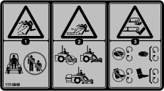
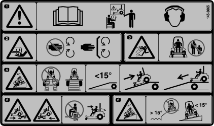
Do not operate the lawnmower on slopes greater than 15°. This reduces the risk of loss of control, slipping, and rollover which may result in personal injury.
-
Exercise extreme caution when working on slopes.This reduces the risk of loss of control, slipping, and rollover which may result in personal injury.
-
Use extreme caution when reversing the lawnmower.Always be aware of your surroundings.
-
Do not touch blades and other hazardous moving parts while they are still in motion.This reduces the risk of injury from moving parts.
-
When clearing jammed material or cleaning the lawnmower, make sure all power switches are off and remove (or activate) the disabling device.Unexpected operation of the lawnmower may result in serious personal injury.
Save all warnings and instructions for future reference.
Additional Safety Messages
Safety-Alert Symbol
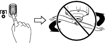
The safety-alert symbol (Figure 2) shown in this manual and on the machine identifies important safety messages that you must follow to prevent accidents.
The safety-alert symbol appears above information that alerts you to unsafe actions or situations and is followed by the word DANGER, WARNING, or CAUTION.
DANGER indicates an imminently hazardous situation which, if not avoided, will result in death or serious injury.
WARNING indicates a potentially hazardous situation which, if not avoided, could result in death or serious injury.
CAUTION indicates a potentially hazardous situation which, if not avoided, may result in minor or moderate injury.
This manual uses two other words to highlight information. Important calls attention to special mechanical information and Note emphasizes general information worthy of special attention.
General Safety
This product is capable of amputating hands and feet and of throwing objects. Always follow all safety instructions to avoid serious personal injury or death.
-
Keep clear of the discharge opening.
-
Allow only responsible and physically capable people to operate the machine.
-
Shut off the machine, remove the key, and wait for all moving parts to stop before leaving the operator's position. Allow the machine to cool before servicing, adjusting, or cleaning it.
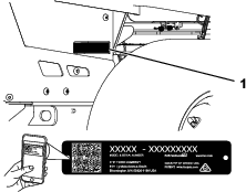
Slope Indicator
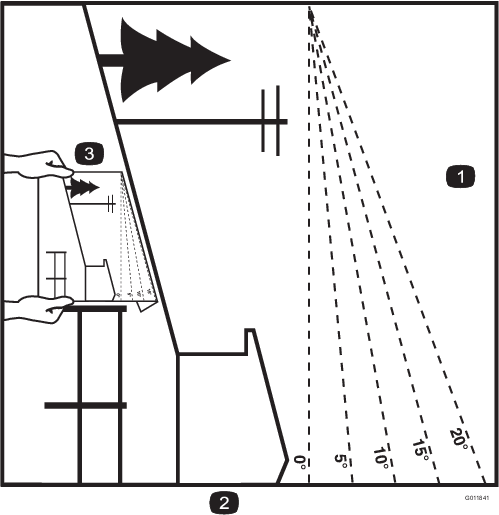
Safety and Instructional Decals
 |
Safety decals and instructions are easily visible to the operator and are located near any area of potential danger. Replace any decal that is damaged or missing. |

Decal 132-5067 is for machines with MyRide only.


Setup
Adjusting the Machine Settings
Use the InfoCenter to adjust the machine settings; refer to InfoCenter Display.
Mounting the Battery Charger on a Wall
Optional
You can mount the charger on a wall using the wall-mount key holes cut into the back of the unit. Use screws that have a 6 mm (1/4 inch) diameter shaft and a head diameter of 11 mm (0.45 inch).
Important: Survey your work area and determine a location that best meets the criteria for safe and effective operation of the charger.
Charging the Batteries
Check the battery-system charge; charge them as needed. Refer to Monitoring the Battery-System Charge Level.
Product Overview
Become familiar with all the controls before you start and operate the machine.
Control Panel
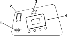
Key Switch
The key switch has 2 positions: ON and OFF.
Use the key switch to turn on or shut off the machine; refer to Starting the Machine and Shutting Off the Machine.
Power-Takeoff Switch (PTO)
Use the power-takeoff switch (PTO) to engage and disengage mower blades; refer to Operating the Mower Blade-Control Switch (PTO).
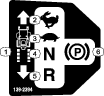
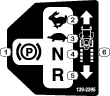
Motion-Control Levers
Use the motion-control levers to drive the machine forward, reverse, and turn either direction.
Park Position
Move the motion-control levers outward from the center to the PARK position when exiting the machine to engage the electric brake.
Always move the motion-control levers to the PARK position when you stop the machine or leave it unattended.
Light Switch
Use the light switch to illuminate and shut off the light.
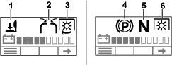
InfoCenter Display
The InfoCenter LCD display shows information about your machine, such as the operating status, various diagnostics, and other information about the machine.
-
Splash screen: shows the battery charge for a few seconds after you move the key to the ON position.

-
Charging screen: shows the battery charge percentage and amperage.

-
Main information screens: shows current machine information while the key is in the ON position. This screen shows the battery-system charge level and the status of various components. Press the
 button to cycle through
the screens. Use the – and + buttons to adjust the maximum traction speed and mower blade speed.
button to cycle through
the screens. Use the – and + buttons to adjust the maximum traction speed and mower blade speed.


 | Next |
 | Scroll up |
 | Scroll down |
 | Enter main menu. |
 | Change language setting. |
 | Increase |
 | Decrease |
 | Exit menu |
 | Save |
 | Operating hours |
 | Battery charge |
 | Operator is off the seat. |
 | Motion-control levers are in the unlocked position. |
 | Motion-control levers are in the NEUTRAL position. |
 | Parking brake is engaged. |
 | PTO is engaged. |
 | Mower blade |
 | Traction drive |
 | Fast |
 | Slow |
 | Energy-saving |
 | The traction speed or menu item is locked. |
InfoCenter Menus
To access the main menu, press the button from any of the
main information screens.
Refer to the following tables for a description of the options available from the menus:
Note:  Protected
under Protected Menus—accessible only by entering PIN.
Protected
under Protected Menus—accessible only by entering PIN.
| Menu Item | Description |
| FAULTS | The FAULTS menu contains a list of the recent machine faults. Refer to the Service Manual or your Authorized Service Dealer for more information on the FAULTS menu. |
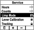
| SERVICE | The Service menu contains information on the machine such as hours of use and counts, power, lever calibration, and tracking. |
| DIAGNOSTICS | The DIAGNOSTICS menu lists various states and data that the machine currently has. You can use this information to troubleshoot certain issues. |
| SETTINGS | The SETTINGS menu allows you to customize and modify configuration variables on the InfoCenter display. |
| ABOUT | The ABOUT menu lists the model number, serial number, and software version (if PIN is entered) of your machine. |
| Menu Item | Description |
| CURRENT | Lists the total number of key-on hours (i.e., hours that the key has been in the ON position). |
| LAST | Indicates the last key-on hour that the fault occurred on. |
| FIRST | Indicates the first key-on hour that the fault occurred on. |
| OCCURRENCES | Indicates the number of fault occurrences. |
| Menu Item | Description |
| HOURS | Lists the total number of hours various components have been
used:
|
| COUNTS | Lists the counts of various components:
|
| MAX SPEED RANGE | Limits the maximum traction speed of the machine; refer to Adjusting the Maximum Speed Range. |
| LIMP MODE | Displays and adjusts the battery percentage before limp mode starts. Refer to Adjusting the Battery Percentage for Limp Mode. |
| LEVER CALIBRATION | Calibrates the motion-control levers. Refer to Calibrating the Levers. |
| TRACKING | Adjusts the tracking of the motion-control levers. Refer to Adjusting the Tracking. |
| Menu Item | Description |
| BATTERY STACK | Indicates the status of the batteries. |
| BATTERY PACKS | Indicates the status of individual batteries. |
| CU MOTORS | Indicates the status of each cutting unit motor. |
| TU MOTORS | Indicates the status of each traction unit motor. |
| Menu Item | Description |
| LANGUAGE | Controls the language used on the InfoCenter. |
| BACKLIGHT | Controls the brightness of the LCD display. |
| CONTRAST | Controls the contrast of the LCD display. |
| PROTECTED MENUS | Allows you to access protected menus by inputting a passcode. |
| Menu Item | Description |
| MODEL | Displays the model number of the machine. |
| SN | Displays the serial number of the machine. |
| MAIN CONTROLLER | Displays the software part number and revision of the main controller. |
| DISPLAY CONTROLLER | Displays the software part number and revision of the display controller. |
| TU MOTORS | Displays the software part number and revision of the traction unit motors. |
| CU MOTORS | Displays the software part number and revision of the cutting unit motors. |
| BATTERY PACKS | Displays the software part number and revision of the battery packs. |
Accessing Protected Menus
Note: The factory default PIN code for your machine is 1234.If you changed the PIN code and forgot the code, contact your Authorized Service Dealer for assistance.
Note: The InfoCenter displays only 2 items at a time; however, the following figures show the full menus for context.
-
In the MAIN MENU, scroll down to SETTINGS and press the
button.
-
In the SETTINGS menu, scroll down to PROTECTED MENUS and press the
button.
-
To enter the PIN code, use the 2 center buttons to input each digit, and press the
button to move on to the next digit. Repeat this
step until the last digit is entered and press the button again.
-
Press the
 button to confirm the PIN code.
Note: If the InfoCenter accepts the PIN code and the protected menu is unlocked, the word “PIN” displays in the upper right corner of the screen.
Note: Specifications and design are subject to change without notice.
| 48-inch Deck | 52-inch Deck | 60-inch Deck | |
|---|---|---|---|
| Deflector up | 140 cm (55 inches) | 150 cm (59 inches) | 165 cm (65 inches) |
| Deflector down | 160 cm (63 inches) | 170 cm (67 inches) | 191 cm (75 inches) |
| Deflector removed | 132 cm (52 inches) | 142 cm (56 inches) | 157 cm (62 inches) |
| All Models | |
|---|---|
| Roll bar up | 206 cm (81 inches) |
| Roll bar down | 216 cm (85 inches) |
| All Models | |
|---|---|
| Roll Bar up (all models) | 183 cm (72 inches) |
| Roll Bar down (MyRide models) | 127 cm (50 inches) |
| Roll Bar down (Non-MyRide models) | 119 cm (47 inches) |
| Model 18748 | Model 18752 | Model 18752TA | Model 18760 | Model 18765 |
|---|---|---|---|---|
| 623 kg (1374 lb) | 630 kg (1389 lb) | 630 kg (1389 lb) | 652 kg (1437 lb) | 687 kg (1515 lb) |
| All Models | |
|---|---|
| Battery Quantity | 10 |
| Rated Voltage | 63 VDC maximum and 55.2 VDC nominal usage |
| Amp Hours | 414 Ah |
Attachments/Accessories
A selection of Toro approved attachments and accessories is available for use with the machine to enhance and expand its capabilities. Contact your Authorized Service Dealer or authorized Toro distributor or go to www.Toro.com for a list of all approved attachments and accessories.
To ensure optimum performance and continued safety certification of the machine, use only genuine Toro replacement parts and accessories. Replacement parts and accessories made by other manufacturers could be dangerous, and such use could void the product warranty.
Operation
Note: Determine the left and right sides of the machine from the normal operating position.
Before Operation
Before Operation Safety
-
Do not operate the machine unless all safety switches and other devices are in place and working properly.
-
Before leaving the operator's position for any reason, do the following:
-
Park the machine on a level surface.
-
Disengage the drives and the power take-off.
-
Engage the parking brake.
-
Shut off the machine and remove the key.
-
Wait for all moving parts to stop.
-
-
Before mowing, always inspect the machine to ensure that the blades, blade bolts, and cutting assemblies are in good working condition.
-
This product generates an electromagnetic field. If you wear an implantable electronic medical device, consult your health care professional before using this product.
-
Use only accessories and attachments approved by Toro.
-
Do not carry passengers on the machine and keep bystanders and pets away from the machine during operation.
-
This machine produces a sound power level that exceeds 85 dBA at the operator’s ear, which can cause hearing loss through extended periods of exposure. Wear hearing protection when operating this machine.
-
Before operating the machine, ensure that the operator presence controls and either the discharge deflector or the entire grass collection system are in place and working properly. Otherwise, do not operate the machine.
-
When you shut off the machine, the blades should stop. If not, stop using the machine immediately and contact an Authorized Service Dealer.
-
Shut off the machine and attachment(s) if anyone enters the area.
Performing Daily Maintenance
Before starting the machine each day, perform the Each Use/Daily procedures listed in .
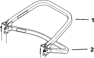
Using the Rollover-Protection System (ROPS)
Warning
To avoid injury or death from rollover, keep the roll bar in the fully raised, locked position and use the seat belt.
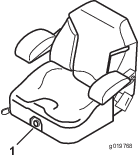
Ensure that the seat is secured to the machine.
Warning
There is no rollover protection when the roll bar is in the down position.
-
Lower the roll bar only when absolutely necessary.
-
Do not wear the seat belt when the roll bar is in the down position.
-
Drive slowly and carefully.
-
Raise the roll bar as soon as clearance permits.
-
Check carefully for overhead clearances (i.e., branches, doorways, electrical wires) before driving under any objects and do not contact them.
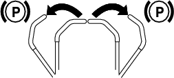
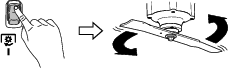
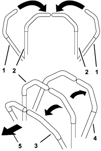
Lowering the Roll Bar
Important: Lower the roll bar only when absolutely necessary.
-
For both sides of the roll bar, remove the hairpin cotter and pin.
-
Lower the roll bar to the down position.
Note: There are 2 down positions, as shown in Figure 19.
-
Install the 2 pins and secure them with the hairpin cotters.
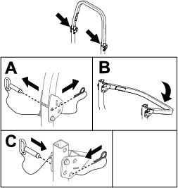
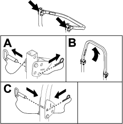
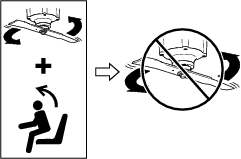
Raising the Roll Bar
Important: Always use the seat belt with the roll bar in the raised position.
-
Remove the hairpin cotters and remove the 2 pins.
-
Raise the roll bar to the upright position.
-
Install the 2 pins, and secure them with the hairpin cotters.
Using the Safety-Interlock System
Danger
If safety-interlock switches are disconnected or damaged, the machine could operate unexpectedly, which will result in serious injury or death.
-
Do not tamper with the interlock switches.
-
Check the operation of the interlock switches daily, and replace any damaged switches before operating the machine.
Understanding the Safety-Interlock System
The safety-interlock system prevents the PTO from engaging unless you do the following:
-
Sit on the seat.
-
Press the ON position on the PTO switch.
Symbols display on the InfoCenter to notify the user when each interlock component is in the correct position.
Testing the Safety-Interlock System
Test the safety-interlock system before you use the machine each time.
Note: If the safety system does not operate as described, have an Authorized Service Dealer repair the safety-interlock system immediately.
-
Sit on the seat and start the machine.
-
Verify that each safety-interlock icon in Figure 21 displays on the InfoCenter when the interlock is active and disappears when it is inactive.
-
Press the ON position on the PTO switch.
Note: The mower blades should engage.
-
Rise slightly from the seat.
Note: The blades should stop.
-
Press the OFF position on the PTO switch and shut off the machine.
Positioning the Seat
The seat can move forward and backward. Position the seat where you have the best control of the machine and are most comfortable.
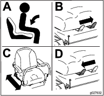
Changing the Seat Suspension
Machines without MyRide™ Suspension System Only
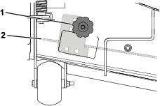
The seat suspension is adjustable to provide a smooth and comfortable ride. Turn the knob either direction to adjust the suspension.
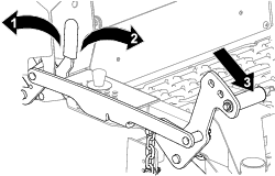
Adjusting the Rear-Shock Assemblies
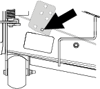
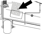
Machines with MyRide™ Suspension System Only
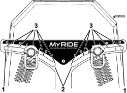
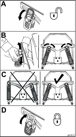
The MyRide™ suspension system adjusts to provide a smooth and comfortable ride. Adjust the rear 2-shock assemblies to quickly and easily change the suspension system to where you are most comfortable.
The slots for the rear-shock assemblies have detent positions for reference. You can position the rear-shock assemblies anywhere in the slot, not just in the detent positions.
Note: Always adjust the left and right rear-shock assemblies to the same positions.
Adjust the rear-shock assemblies as shown.
During Operation
During Operation Safety
General Safety
-
Wet grass or leaves can cause serious injury if you slip and contact the blade. Avoid mowing in wet conditions.
-
Before you start the machine, ensure that all drives are in neutral.
-
Keep away from holes, ruts, bumps, rocks, and other hidden hazards. Use care when approaching blind corners, shrubs, trees, tall grass or other objects that may hide obstacles or obscure vision. Uneven terrain could overturn the machine or cause you to lose your balance or footing.
-
Shut off the machine and disengage the drive to the cutting unit after striking a foreign object or if an abnormal vibration occurs. Inspect the cutting unit for damage and make repairs before starting and operating the machine.
-
Be alert, slow down, and use caution when making turns and crossing roads and sidewalks with the machine. Always yield the right-of-way.
-
Do not use the machine as a towing vehicle.
-
Never raise the mower deck with the blades running.
-
Be aware of the mower discharge path and direct discharge away from others. Avoid discharging material against a wall or obstruction as the material may ricochet back toward the operator. Stop the blades, slow down, and use caution when crossing surfaces other than grass and when transporting the mower.
-
Do not leave a running machine unattended.
-
Be alert and shut off the machine if children enter the area.
Slope Safety
-
Slopes are a major factor related to loss of control and rollover accidents, which can result in severe injury or death. You are responsible for safe slope operation. Operating the machine on any slope requires extra caution. Before using the machine on a slope, do the following:
-
Review and understand the slope instructions in the manual and on the machine.
-
Use an angle indicator to determine the approximate slope angle of the area.
-
Never operate on slopes greater than 15°.
-
Evaluate the site conditions of the day to determine if the slope is safe for machine operation. Use common sense and good judgment when performing this evaluation. Changes in the terrain, such as moisture, can quickly affect the operation of the machine on a slope.
-
-
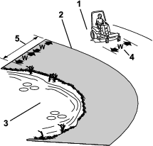
Identify hazards at the base of the slope. Do not operate the machine near drop-offs, ditches, embankments, water, or other hazards. The machine could suddenly roll over if a wheel goes over the edge or the edge collapses. Keep a safe distance (twice the width of the machine) between the machine and any hazard. Use a walk-behind machine or a handheld tool to operate in these areas.
-
Avoid starting, stopping, or turning the machine on slopes. Avoid making sudden changes in speed or direction; turn slowly and gradually.
-
Do not operate a machine under any conditions where traction, steering or stability is in question. Be aware that operating the machine on wet grass, across slopes or downhill may cause the machine to lose traction. Loss of traction to the drive wheels may result in sliding and a loss of braking and steering. The machine can slide even if the drive wheels are stopped.
-
Remove or mark obstacles such as ditches, holes, ruts, bumps, rocks or other hidden hazards. Tall grass can hide obstacles. Uneven terrain could overturn the machine.
-
Use extra care while operating with accessories or attachments. These can change the stability of the machine and cause a loss of control. Follow directions for counterweights.
-
If possible, keep the deck lowered to the ground while operating on slopes. Raising the deck while operating on slopes can cause the machine to become unstable.
Rollover Protection System (ROPS) Safety
-
The ROPS is an integral and effective safety device. Do not remove or alter the ROPS.
-
There is no rollover protection when the roll bar is down.
-
Keep the roll bar in the fully raised and locked position and always wear your seat belt whenever the roll bar is up.
-
Ensure that the seat belt can be released quickly in the event of an emergency.
-
Lower the roll bar only when absolutely necessary. Do not wear the seat belt when the roll bar is down.
-
Raise the roll bar as soon as clearance permits.
-
Wheels dropping over edges, ditches, steep banks, or water can cause rollovers, which may result in serious injury or death.
-
Check carefully for overhead clearances before driving under any objects and do not contact them.
-
In the event of a rollover, take the machine to an Authorized Service Dealer and have the ROPS inspected.
-
Replace damaged ROPS components. Do not repair or alter them.
-
Use only accessories and attachments installed on the ROPS that are approved by Toro.
Entering the Operator’s Position
Use the mower deck as a step to get into the operator’s position.
Starting the Machine
-
Sit on the seat.
-
Turn the key switch to the ON position.
Shutting Off the Machine
Caution
Children or bystanders may be injured if they move or attempt to operate the machine while it is unattended.
Always remove the key and engage the parking brake when leaving the machine unattended.
-
Disengage the PTO.
-
Move the motion-control levers outward to the PARK position.
Note: The electric brake will engage automatically.
-
Turn the key switch to the OFF position and remove the key.
-
Wait for all moving parts to stop before leaving the operating position.
Operating the Mower Blade-Control Switch (PTO)
The blade-control switch (PTO) starts and stops the mower blades.
Danger
The rotating blades under the mower deck are dangerous. Blade contact will cause serious injury or death.
Do not put your hands or feet under the mower or mower deck when the blades are engaged.
Danger
An uncovered discharge opening allows objects to be thrown toward you or bystanders. Also, contact with the blade could occur. Thrown objects or blade contact will cause serious injury or death.
Do not operate the mower with the discharge deflector raised, removed, or altered unless a grass collection system or mulch kit is in place and working properly.
Engaging the Blade-Control Switch (PTO)
Disengaging the Blade-Control Switch (PTO)
Driving the Machine
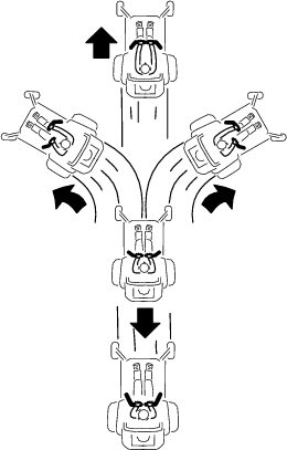
The drive wheels turn independently, powered by motors on each axle. You can turn 1 side in reverse while you turn the other forward, causing the machine to spin rather than turn. This greatly improves the machine maneuverability but may require some time for you to adapt to how it moves.
Caution
Positioning one lever too far in front of the other causes the machine to spin very rapidly. As a result, you may lose control of the machine, causing personal injury to you and damage to the machine.
Slow down the machine before making sharp turns.
-
Move the motion-control levers down to the center, unlocked position.
-
Slowly push the motion-control levers forward or rearward. Move 1 lever farther than the other lever to turn.
Note: The farther you move the motion-control levers, the faster the machine moves in that direction.
-
To stop, pull the motion-control levers back to the NEUTRAL position.
Side Discharging or Mulching the Grass
This machine has a hinged grass deflector that disperses clippings to the side and down toward the turf.
Danger
Without the grass deflector, discharge cover, or complete grass catcher assembly mounted in place, you and bystanders are exposed to blade contact and thrown debris. Contact with rotating mower blade(s) and thrown debris will cause injury or death.
-
Do not remove the grass deflector from the machine, because the grass deflector routes material down toward the turf. If the grass deflector is ever damaged, replace it immediately.
-
Never try to clear the discharge area or mower blades unless the power takeoff (PTO) is off. Rotate the key to the OFF position and remove the key.
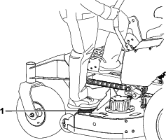
Using the Transport Lock
-
Push the deck-lift pedal fully forward to lock the mower deck in the TRANSPORT position.
-
Push the deck-lift pedal forward and push the transport lock forward to the UNLOCK position, then slowly lower the mower deck.
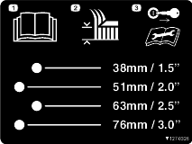
Adjusting the Height-of-Cut
You can adjust the height of cut from 38 to 140 mm (1-1/2 to 5-1/2 inches) in 6 mm (1/4 inch) increments.
-
Push the deck-lift pedal fully forward to lock the mower deck in the Transport position (also the 140 mm or 5-1/2 inches height-of-cut position).
-
Remove the pin from the height-of-cut bracket.
-
Select a hole in the height-of-cut bracket corresponding to the height of cut desired, and insert the pin.
-
Push the deck-lift pedal forward, push the transport lock forward, and slowly lower the mower deck.
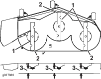
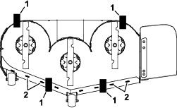
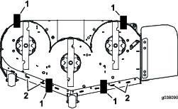
Adjusting the Anti-Scalp Rollers
Whenever you change the height-of-cut, adjust the height of the anti-scalp rollers.
-
Park the machine on a level surface, disengage the PTO, and move the motion-control levers outward to the PARK position.
-
Shut off the machine, remove the key, and wait for all moving parts to stop before leaving the operating position.
-
Adjust the anti-scalp rollers as shown.
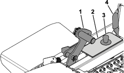
Positioning the Flow Baffle
The following figures are recommendations only. Adjustments vary by grass type, moisture content, and the height of the grass.
Remove the knob and carriage bolt, adjust the baffle to the appropriate position, and install the knob and carriage bolt.
Note: Some machines will use the outer or inner holes, depending on the size of the mower deck.
Note: If the power draws down and the mower ground speed is the same, open the baffle.
Position A
This is the fully-rear position. The suggested use for this position is as follows:
-
Short, light grass mowing conditions
-
Dry conditions
-
Smaller grass clippings
-
Propels grass clippings farther away from the mower
Position B
Use this position when bagging.
Position C
This is the fully-forward position. The suggested use for this position is as follows:
-
Tall, dense grass mowing conditions
-
Wet conditions
-
Lowers the power consumption
-
Allows increased ground speed in heavy conditions
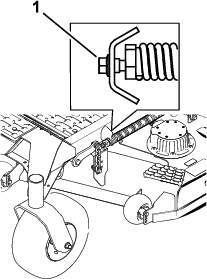
Adjusting the Rake of the Mower Deck
Adjusting the rake of the mower deck can improve the machine run time. You can raise the rear of the mower deck in 6.3 mm (1/4 inch) increments, up to 25.4 mm (1 inch).
-
Park the machine on a level surface, disengage the PTO, and move the motion-control levers outward to the PARK position.
-
Shut off the machine, remove the key, and wait for all moving parts to stop before leaving the operating position.
-
Raise the mower deck to the Transport position.
-
Loosen the jam nut.
-
Turn the bolt to move the adjustment yoke until the edge aligns with the desired slope on the decal.
-
Tighten the jam nut.
Monitoring the Battery-System Charge Level
Refer to the main information screen in the InfoCenter to determine the battery-system charge level.
-
Low battery: When the battery level reaches a low percentage, a low-battery advisory appears on the InfoCenter.
Finish mowing, then transport the machine to a designated battery-charging area and charge the batteries.
-
Limp mode: If the battery level drops below the set limp-mode battery percentage, an advisory appears on the InfoCenter, and the mower blades will disengage and cannot be engaged.
Transport your machine to a designated battery-charging area and charge the batteries.
-
Ultra-limp mode: If the battery level becomes too low during limp mode, an advisory appears on the InfoCenter and traction speed automatically decreases.
Transport your machine to a designated battery-charging area and charge the batteries.
Refer to Charging the Lithium-Ion Batteries.
Adjusting the Battery Percentage for Limp Mode
Note: The InfoCenter displays only 2 items at a time; however, the following figures show the full menus for context.
-
Park the machine on a level surface, disengage the PTO, and move the motion-control levers outward to the PARK position.
-
In the MAIN MENU, scroll down to SERVICE and press the
button.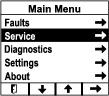
-
In the SERVICE menu, scroll down to LIMP MODE and adjust the percentage using the – and + buttons.
After Operation
After Operation Safety
-
Disengage the PTO whenever you are transporting or not using the machine.
-
Use full-width ramps for loading the machine into a trailer or truck.
-
Tie the machine down securely using straps, chains, cable, or ropes. Both front and rear straps should be directed down and outward from the machine.
-
Replace all worn, damaged, or missing parts and decals. Keep all fasteners tight to ensure that the machine is working properly.
Battery and Charger Safety
General
-
WARNING: Risk of fire and electric shock—The batteries have no user-serviceable parts.
-
Confirm the voltage that is available in your country before using the charger.
-
Do not get the charger wet; keep it protected from rain and snow.
-
A risk of fire, electric shock, or injury may result from using an accessory not recommended or sold by Toro.
-
To reduce risk of a battery explosion, follow these instructions and the instructions for any equipment that you intend to use near the charger.
-
Batteries could emit explosive gasses if they are significantly overcharged.
-
Refer to an Authorized Service Dealer to service or replace a battery.
Training
-
Never allow children or untrained people to operate or service the charger. Local regulations may restrict the age of the operator. The owner is responsible for training all operators and mechanics.
-
Read, understand, and follow all instructions on the charger and in the manual before operating the charger. Be familiar with the proper use of the charger.
Preparation
-
Keep bystanders and children away while charging.
-
Wear appropriate clothing while charging, including eye protection; long pants; and substantial, slip-resistant footwear.
-
Shut off the machine and wait until the machine has completely powered down before charging. Failure to do this may cause arcing.
-
Ensure that the area is well ventilated while charging.
-
The charger is for use on only nominal 120 to 240 VAC operation. For use with 240 V circuits, contact your Authorized Service Dealer for the correct power cord.
Operation
-
Do not charge a frozen battery.
-
Do not abuse the cord. Do not carry the charger by the cord or yank on the power supply cord to disconnect the charger from the receptacle. Keep the cord from heat, oil, and sharp edges.
-
Connect the charger directly to a grounding receptacle. Do not use the charger on an ungrounded outlet, even with a grounding adapter.
-
Do not alter the provided power cord or plug.
-
Remove metal items such as rings, bracelets, necklaces, and watches when working with a lithium-ion battery. A lithium-ion battery can produce enough current to cause a severe burn.
-
Never operate the charger without good visibility or light.
-
Use an extension cord capable of handling 15 A or more. If you are charging outdoors, use an extension cord rated for outdoor use.
-
If the power supply cord is damaged while it is plugged in, disconnect the cord from the wall receptacle and contact an Authorized Service Dealer for a replacement.
-
Unplug the charger from the electrical outlet when not in use, before moving it to another location, or prior to servicing it.
Maintenance and Storage
-
Store the charger indoors in a dry, secure place that is out of the reach of unauthorized users.
-
Do not disassemble the charger. Take the charger to an Authorized Service Dealer when service or repair is required.
-
Unplug the power cord from the outlet before starting any maintenance or cleaning to reduce risk of electric shock.
-
Maintain or replace safety and instruction labels as needed.
-
Do not operate the charger with a damaged cord or plug. Contact an Authorized Service Dealer to obtain a replacement cord.
-
If the charger has received an impact, been dropped, or otherwise damaged, do not use it; take it to an Authorized Service Dealer.
Moving a Non-Functioning Machine
Important: Do not tow the machine without first disengaging the transmission, otherwise you could damage motor components.
Caution
The machine does not have brakes when the transmission is disengaged. It will roll uncontrolled, possibly causing injury.
Use caution when towing the machine and engage the transmission after moving it.
-
Disengage the PTO and move the motion-control levers outward to the PARK position.
-
Shut off the machine, remove the key, and wait for all moving parts to stop before leaving the operating position.
-
Remove the cap from the motor.
-
Disengage the transmission.
-
Insert a ratchet with a 3/8 inch drive into the square hole in the motor hub.
-
Rotate it counterclockwise until it stops (approximately 4 full rotations) to disengage the transmission.
-
Torque to 41 to 68 N∙m (30 to 50 ft-lb).
Note: The wheel will spin freely.
-
-
Repeat for the other motor.
-
Move the machine to the desired location.
Important: Do not move the machine faster than 8 km/h (5 mph).
-
Immediately after moving the machine, engage the transmission for operation.
-
Insert a ratchet with a 3/8 inch drive into the square hole in the motor hub.
-
Rotate it clockwise until it stops (approximately 4 full rotations).
-
Torque to 41 to 68 N∙m (30 to 50 ft-lb).
-
Transporting the Machine
Use a heavy-duty trailer or truck to transport the machine. Use a full-width ramp. Ensure that the trailer or truck has all the necessary brakes, lighting, and marking as required by law. Please carefully read all the safety instructions. Knowing this information could help you or bystanders avoid injury. Refer to your local ordinances for trailer and tie-down requirements.
Warning
Driving on the street or roadway without turn signals, lights, reflective markings, or a slow-moving-vehicle emblem is dangerous and can lead to accidents, causing personal injury.
Do not drive the machine on a public street or roadway.
Warning
Loading a machine onto a trailer or truck increases the possibility of backward tip-over and could cause serious injury or death.
-
Use only full-width ramps; do not use individual ramps for each side of the machine.
-
Ensure that the roll bar is in the up position and use the seat belt when loading or unloading the machine. Ensure that the roll bar will clear the top of an enclosed trailer.
-
Do not exceed a 15-degree angle between the ramp and the ground or between the ramp and the trailer or truck.
-
Ensure that the length of ramp is at least 4 times as long as the height of the trailer or truck bed to the ground.
-
Use extreme caution when operating a machine on a ramp.
-
Back the machine up the ramp and drive it forward down the ramp.
-
Avoid sudden acceleration or deceleration while driving the machine on a ramp as this could cause a loss of control or a tip-over situation.
Selecting a Trailer
Loading the Machine
-
If using a trailer, connect it to the towing vehicle and connect the safety chains.
-
If applicable, connect the trailer brakes and lights.
-
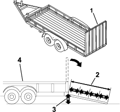
Lower the ramp, ensuring that the angle between the ramp and the ground does not exceed 15 degrees (Figure 49).
-
Back the machine up the ramp.
-
Shut off the machine, remove the key, and engage the parking brake.
-
Tie down the machine near the front caster wheels and the rear frame with straps, chains, cable, or ropes. Refer to local regulations for tie-down requirements.
Transporting the Lithium-Ion Batteries
The US Department of Transportation and international transportation authorities require that lithium-ion batteries be transported using special packaging and only be transported by carriers certified to haul them. In the US, you are allowed to transport a battery when it is installed on the machine as battery powered equipment, with some regulatory requirements. Contact the US Department of Transportation or the appropriate government body in your country for detailed regulations on transportation of your batteries or the machine with the batteries equipped.
For detailed information on shipping a battery, contact your Authorized Service Dealer.
Using the Lithium-Ion Battery Charger
Refer to Figure 52 for an overview of the battery-charger cords.
Connecting to a Power Source
Danger
Contact with water while charging the machine could cause electric shock, causing injury or death.
-
Do not handle the plug or the charger with wet hands or while standing in water.
-
Do not charge the batteries in the rain or in wet conditions.
To reduce the risk of electric shock, this charger has a 3-prong grounded plug (type B). If the plug does not fit into the wall receptacle, other grounded plug types are available; contact an Authorized Service Dealer.
Do not change the charger or the power-supply-cord plug in any way.
Important: Check the power supply cord periodically for holes or cracks in the insulation. Do not use a damaged cord. Do not run the cord through standing water or wet grass.
-
Insert the charger plug on the power-supply cord into the matching input power socket on the charger.
Warning
A damaged charger cord can cause an electrical shock or a fire.
Thoroughly inspect the power supply cord before using the charger. If the cord is damaged, do not operate the charger until you obtain a replacement.
-
Insert the wall plug end of the power supply cord into a grounded electrical outlet.
Charging the Lithium-Ion Batteries
Caution
Attempting to charge the batteries with a charger not provided by Toro can result in excessive heat and other related product malfunctions, which can lead to property damage and/or injury.
Use the Toro-provided chargers to charge the batteries.
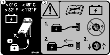
Recommended temperature range for charging: 0° to 45°C (32° to 113°F)
Important: Charge the batteries only in temperatures within the recommended range.
Note: The charger will not function in temperatures exceeding the minimum or maximum temperatures.
-
Park the machine in the designated location for charging.
-
Shut off the machine and remove the key.
Note: Do not turn the battery-disconnect switch to the OFF position, otherwise the batteries will not charge.
-
Ensure that the connectors are free of dust and debris.
-
Slide the charger-output connector into the charger connector on the machine.
-
Connect the charger power cord to a power source.
-
Ensure that the InfoCenter screen shows that the batteries are charging.
Note: The InfoCenter shows the battery charge percentage and amperage. Batteries with a lower voltage charge first; once they reach the voltage of the other batteries, all batteries charge simultaneouslyWhen charging is complete, the machine InfoCenter displays 10 solid bars

-
When the machine reaches a sufficient level, disconnect the charger connector from the machine connector.
-
Place the charger connector and cord in a storage position that avoids damage.
-
Start the machine.
-
Verify the charge level using the InfoCenter display.
Maintenance
Note: Determine the left and right sides of the machine from the normal operating position.
Warning
Modifying the original machine, parts, and/or accessories may alter the warranty, controllability, and safety of the machine. Making unauthorized modifications to the original machine and/or not using genuine Toro parts could lead to serious injury or death.
-
Do not make unauthorized modifications to the machine, parts, and/or accessories.
-
Use only genuine Toro parts.
Maintenance Safety
-
Before adjusting, cleaning, servicing, or leaving the machine, do the following:
-
Park the machine on a level surface.
-
Disengage the drives and the power take-off.
-
Engage the parking brake.
-
Shut off the machine and remove the key.
-
Wait for all moving parts to stop.
-
Allow machine components to cool.
-
-
Carefully release pressure from components with stored energy.
-
Check the parking brake operation frequently. Service the brake as needed.
-
Never tamper with safety devices. Check their proper operation regularly.
-
Do not rely solely on mechanical or hydraulic jacks to support the machine; support the machine with jack stands whenever you raise the machine.
-
Use care when checking the blades. Wrap the blades or wear gloves, and use caution when servicing the blades. Only replace or sharpen the blades; never straighten or weld them.
-
On multi-bladed machines, take care as rotating one blade can cause other blades to rotate.
-
Keep your hands and feet away from hot surfaces.
-
Keep all hardware tightened, especially the blade-attachment hardware.
Recommended Maintenance Schedule(s)
| Maintenance Service Interval | Maintenance Procedure |
|---|---|
| After the first 50 hours |
|
| After the first 100 hours |
|
| Before each use or daily |
|
| Every 50 hours |
|
| Every 100 hours |
|
| Every 500 hours |
|
| Before storage |
|
| Yearly |
|
Pre-Maintenance Procedures
Raising the Machine
Whenever you raise the rear of the machine, support the machine under the rear bracket.
Important: Do not support the machine under the batteries; otherwise, you could damage the batteries.
Removing the Rear Cover
-
Park the machine on a level surface, disengage the blade-control switch, and move the motion-control levers outward to the PARK position.
-
Shut off the machine, remove the key, and wait for all moving parts to stop before leaving the operating position.
-
Turn the battery-disconnect switch to the OFF position.
-
Remove the 8 screws securing the rear cover.
-
Remove the cover.
Lubrication
Lubricating the Mower Deck-Lift Pivots
| Maintenance Service Interval | Maintenance Procedure |
|---|---|
| Every 100 hours |
|
Use light oil or spray lubricant to lubricate the deck-lift pivots.
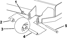
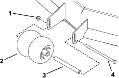
Greasing the Caster-Wheel Hubs
| Maintenance Service Interval | Maintenance Procedure |
|---|---|
| Yearly |
|
Grease type: Lithium or molybdenum grease
-
Park the machine on a level surface, disengage the PTO, and move the motion-control levers outward to the PARK position.
-
Shut off the machine, remove the key, and wait for all moving parts to stop before leaving the operating position.
-
Remove the caster wheel from the caster forks.
-
Remove the seal guards from the wheel hub.

-
Remove 1 spacer nut from the axle assembly in the caster wheel.
Note: Thread-locking adhesive has been applied to lock the spacer nuts to the axle.
-
Remove the axle with the other spacer nut still assembled to it from the wheel assembly.
-
Pry out the seals, inspect bearings for wear or damage, and replace them if necessary.
-
Pack the bearings with a general-purpose grease.
-
Insert 1 bearing and 1 new seal into the wheel.
Note: You must replace the seals.
-
If both spacer nuts in the axle assembly have been removed (or broken loose), apply thread-locking adhesive to 1 spacer nut, threading it onto the axle with the wrench flats facing outward.
Note: Do not thread the spacer nut all of the way onto the end of the axle. Leave approximately 3 mm (1/8 inch) from the outer surface of the spacer nut to the end of the axle inside the nut.
-
Insert the assembled nut and axle into the wheel on the side of the wheel with the new seal and bearing.
-
With the open end of the wheel facing up, fill the area inside the wheel around the axle full of general-purpose grease.
-
Insert the second bearing and the new seal into the wheel.
-
Apply thread-locking adhesive to the second spacer nut, threading it onto the axle with the wrench flats facing outward.
-
Torque the nut to 8 to 9 N∙m (71 to 80 in-lb), loosen it, then torque it to 2 to 3 N∙m (20 to 25 in-lb).
Note: Make sure that the axle does not extend beyond either nut.
-
Install the seal guards over the wheel hub and insert the wheel into the caster fork.
-
Install the caster bolt and tighten the nut fully.
Important: To prevent seal and bearing damage, check the bearing adjustment often by spinning the caster wheel. The wheel should not spin freely (more than 1 or 2 revolutions) or have any side play. If the wheel spins freely, adjust the torque on the spacer nut until there is a slight amount of drag, then apply thread-locking adhesive.
Electrical System Maintenance
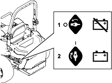
Using the Battery-Disconnect Switch
-
Park the machine on a level surface, disengage the PTO, and move the motion-control levers outward to the PARK position.
-
Shut off the machine, remove the key, and wait for all moving parts to stop before leaving the operating position.
-
Unplug the battery charger if it is connected.
-
Position the battery disconnect switch to electrically de-energize or energize the machine.
Servicing the Batteries
Note: The machine is equipped with 10 lithium-ion batteries.
A lithium-ion battery must be disposed of or recycled in accordance with local and federal regulations. If a battery requires service, contact your Authorized Service Dealer for assistance.
Do not open the main compartment of a battery. If you are having problems with a battery, contact your Authorized Service Dealer for assistance.
Maintaining the Lithium-Ion Batteries
Warning
The batteries contain high voltage, which could burn or shock you.
-
Do not attempt to open the batteries.
-
Use extreme care when handling a battery with a cracked case.
-
Use only the charger designed for the batteries.
The lithium-ion batteries hold a sufficient charge to perform intended work during its life span.
To achieve maximum life and use from your batteries, follow these guidelines:
-
Do not open the battery.
-
Store/park the machine in a clean, dry garage or storage area, away from direct sunlight, heat sources, rain, and wet conditions. Do not store it in a location where the temperature exceeds the range specified in Battery Storage Requirements. Temperatures outside of this range will damage your batteries. High temperatures during storage, especially at a high state of charge, reduces the life of the batteries.
-
When storing the machine for more than 10 days, ensure that the machine is in a cool and dry location, out of sunlight, rain, and wet conditions.
-
If you are mowing in hot conditions or in strong, direct sunlight, the battery may overheat. If this happens, a high-temperature alert will appear on the InfoCenter, the cutting units will disengage, and the machine will slow down.
Immediately drive the machine to a cool location out of the sun, turn off the machine, and allow the batteries to cool fully before resuming operation.
-
Maintain the sharpness of the mower blades. A dull blade increases power consumption and reduces the amount of work that the machine performs on each charge.
-
Use lights only when it is necessary.
Maintaining the Battery Charger
Important: All electrical repairs should be performed by an Authorized Toro Dealer only.
The charger requires little maintenance other than protecting it from damage and weather.
-
Clean the battery-charger cords and case with a slightly damp cloth after each use.
Note: Do not clean the dielectric grease from the terminals.
-
Coil the cords when not in use.
-
Periodically examine the cords for damage, and replace them when necessary with Toro-approved parts.
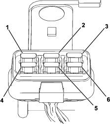
Locating the Fuses
The electrical system is protected by fuses. It requires no maintenance. Refer to the Service Manual for information on testing and servicing the motor fuses.
Remove the rear cover to access the fuses.

Drive System Maintenance
Checking the Seat Belt
| Maintenance Service Interval | Maintenance Procedure |
|---|---|
| Before each use or daily |
|
Inspect the seat belt for wear, cuts, and proper operation of the retractor and buckle. Replace the seat belt if it is damaged.
Checking the Tire Pressure
| Maintenance Service Interval | Maintenance Procedure |
|---|---|
| Every 50 hours |
|
Maintain the air pressure in the rear tires at 83 to 97 kPa (12 to 14 psi).
Important: Uneven tire pressure can cause an uneven cut.
Note: The front tires are semi-pneumatic tires and do not require air-pressure maintenance.
Checking the Wheel-Lug Nuts
| Maintenance Service Interval | Maintenance Procedure |
|---|---|
| After the first 100 hours |
|
Check and torque the wheel-lug nuts to 75 to 88 N∙m (55 to 65 ft-lb).
Changing the Transmission Fluid
| Maintenance Service Interval | Maintenance Procedure |
|---|---|
| After the first 50 hours |
|
| Every 500 hours |
|
Fluid type: Toro Synthetic HV Electric Motor Drive Oil
Capacity: 150 mL (5 fl oz)
-
Park the machine on a level surface, disengage the PTO, and move the motion-control levers outward to the PARK position.
-
Shut off the machine, remove the key, and wait for all moving parts to stop before leaving the operating position.
-
Remove the tire.
-
Place a drain pan under the transmission.
-
Remove the top plug and bottom plug. Allow the fluid to drain.
-
Install the bottom plug and torque it to 7 to 8 N∙m (62 to 70 in-lb).
-
Remove a side plug.
-
Add fluid, as specified at the beginning of this procedure, through the top hole until the level reaches the side plug opening.
-
Install the top plug and side plug . Torque them to 7 to 8 N∙m (62 to 70 in-lb).
-
Install the tire and torque the lug nuts to 75 to 88 N∙m (55 to 65 ft-lb).
-
Repeat for the other transmission.
Adjusting the Maximum Speed Range
Note: The InfoCenter displays only 2 items at a time; however, the following figures show the full menus for context.
-
Park the machine on a level surface, disengage the PTO, and move the motion-control levers outward to the PARK position.
-
Enable access to protected menus; refer to Accessing Protected Menus.
-
In the MAIN MENU, scroll down to SERVICE and press the
button . -
In the SERVICE menu, scroll down to MAX SPEED RANGE and press the
button.
-
Adjust the maximum speed range as desired.
Note: The number indicates the maximum speed setting (2 through 7) that the operator can select on the main information screen as shown.

-
Press the
 button to save the new value.
Controls System Maintenance
Adjusting the Control-Handle Position
Adjusting the Height
You can adjust the motion control levers higher or lower for maximum comfort.
-
Park the machine on a level surface, disengage the blade-control switch (PTO), and move the motion-control levers outward to the PARK position.
-
Shut off the machine, remove the key, and wait for all moving parts to stop before leaving the operating position.
-
Remove the hardware holding the motion-control lever to the control-arm shaft.
-
Move the control lever to the next set of holes. Secure the lever with the hardware.
-
Repeat the adjustment for the opposite control lever.
Adjusting the Tilt
-
Park the machine on a level surface, disengage the blade-control switch (PTO), and move the motion-control levers outward to the PARK position.
-
Shut off the machine, remove the key, and wait for all moving parts to stop before leaving the operating position.
-
Loosen the upper bolt holding the control lever to the control arm shaft.
-
Loosen the lower bolt just enough to pivot the control lever fore or aft. Tighten both bolts to secure the control in the new position.
-
Repeat the adjustment for the opposite control lever.

Calibrating the Levers
Note: The InfoCenter displays only 2 items at a time; however, the following figures show the full menus for context.
-
Park the machine on a level surface, disengage the PTO, and move the motion-control levers outward to the PARK position.
-
Enable access to protected menus; refer to Accessing Protected Menus.
-
In the MAIN MENU, scroll down to SERVICE and press the
button . -
In the SERVICE menu, scroll down to LEVER CALIBRATION and press the
button.
-
Follow the prompts on the screen. Press the
 button after each step;
to exit calibration, press the Exit button.
button after each step;
to exit calibration, press the Exit button.Screen Action 
Press the button.
Hold the left motion-control lever in the full FORWARD position and press the button.
Hold the left motion-control lever in the full REVERSE position and press the button.
Hold the left motion-control lever in the NEUTRAL position and press the button.
Hold the right motion-control lever in the full FORWARD position and press the button.
Hold the right motion-control lever in the full REVERSE position and press the button.
Hold the right motion-control lever in the NEUTRAL position and press the button.
Press the button. -
When you complete, exit, or fail calibration, shut off then start the machine to clear the screen.

Adjusting the Tracking
If you push both motion-control levers forward the same distance and the machine pulls to 1 side, adjust the tracking as follows.
Note: The InfoCenter displays only 2 items at a time; however, the following figures show the full menus for context.
-
Park the machine on a level surface, disengage the PTO, and move the motion-control levers outward to the PARK position.
-
In the MAIN MENU, scroll down to SERVICE and press the
button. -
In the SERVICE menu, scroll down to TRACKING and press the
button.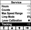
-
Adjust the tracking to the left or right.
Note: Adjusting the tracking to the left causes the machine to steer toward the left; adjusting the tracking to the right causes the machine to steer toward the right.

-
Press the
button.
Mower Deck Maintenance
Servicing the Cutting Blades
To ensure a superior quality of cut, keep the blades sharp. For convenient sharpening and replacement, keep extra blades on hand.
Before Inspecting or Servicing the Blades
-
Park the machine on a level surface, disengage the PTO, and move the motion-control levers outward to the PARK position.
-
Shut off the machine, remove the key, and wait for all moving parts to stop before leaving the operating position.
-
Unplug the battery charger if it is connected.
-
Turn the battery-disconnect switch to the OFF position.
Inspecting the Blades
| Maintenance Service Interval | Maintenance Procedure |
|---|---|
| Before each use or daily |
|
-
Inspect the cutting edges.
-
If the edges are not sharp or have nicks, remove and sharpen the blade; refer to Sharpening the Blades.
-
Inspect the blades, especially in the curved area.
-
If you notice any cracks, wear, or a slot forming in this area, immediately install a new blade.
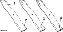
Checking for Bent Blades
Warning
A blade that is bent or damaged could break apart and could critically injure you or bystanders.
-
Always replace a bent or damaged blade with a new blade.
-
Do not file or create sharp notches in the edges or surfaces of the blade.
-
Rotate the blades until the ends face forward and backward.
-
Measure from a level surface to the cutting edge, position A, of the blades.
-
Rotate the opposite ends of the blades forward.
-
Measure from a level surface to the cutting edge of the blades at the same position as in step 2 above.
Note: The difference between the dimensions obtained in steps 2 and 3 must not exceed 3 mm (1/8 inch).
Note: If this dimension exceeds 3 mm (1/8 inch), replace the blade.
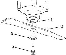
Removing the Blades
Replace the blades if they hit a solid object or if the blade is out of balance or bent.
-
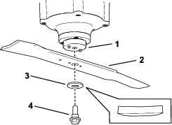
Place a wrench on the flat of the blade retainer or hold the blade end using a rag or thickly padded glove.
-
Remove the blade bolt, washer, and blade from the spindle shaft.
Sharpening the Blades
-
Use a file to sharpen the cutting edge at both ends of the blade.
Note: Maintain the original angle.
Note: The blade retains its balance if the same amount of material is removed from both cutting edges.
-
Check the balance of the blade by putting it on a blade balancer.
Note: If the blade stays in a horizontal position, the blade is balanced and can be used. If the blade is not balanced, file some metal off the end of the sail area only.
-
Repeat this procedure until the blade is balanced.
Installing the Blades
Warning
Operating a machine after incorrectly installing the blade assembly and/or not using genuine Toro blade and blade hardware could allow a blade or blade component to be thrown out from under the deck, resulting in serious injury or death.
Always install genuine Toro blades and blade hardware according to the instructions.
-
Install the blade to the shaft.
Note: Ensure that the washer curves downward, as shown, to ensure proper cutting.
-
Place a wrench on the flat of the spindle shaft and torque the blade bolt to 75 to 81 N∙m (55 to 60 ft-lb).
Leveling the Mower Deck
Preparing the Machine
Ensure that the mower deck is level any time you install the mower deck or when you see an uneven cut on your lawn.
Level the mower deck side to side before adjusting the front-to-rear slope.
-
Park the machine on a level surface, disengage the PTO, and move the motion-control levers outward to the PARK position.
-
Shut off the machine, remove the key, and wait for all moving parts to stop before leaving the operating position.
-
Unplug the battery charger if it is connected.
-
Turn the battery-disconnect switch to the OFF position.
-
Check the tire pressure of both drive tires; refer to Checking the Tire Pressure.
-
Check the mower deck for bent blades; remove and replace any bent blades; refer to Servicing the Cutting Blades.
-
Raise the mower deck to the transport-lock position or the highest height-of-cut setting.
-
Set the rake of the mower deck to the lowest setting; refer to Adjusting the Rake of the Mower Deck.
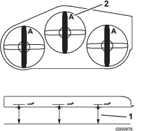
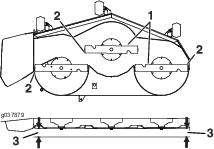
Checking the Mower Deck Side-to-Side Height
-
Position the blades side to side.
-
Measure between the blade tip and the flat surface.
Note: If both measurements are not within 5 mm (3/16 inch), an adjustment is required; refer to Leveling the Mower Deck
Checking the Mower Deck Front-to-Rear Pitch
-
With the machine on level surface, position the blades front-to-rear.
-
Measure from the tip of the front blade to the flat surface and the tip of the rear blade to the flat surface.
Note: The mower blades should be 4.8 to 6 mm (3/16 to 1/4 inch) lower in front than in the rear.
Leveling the Mower Deck
-
Set the anti-scalp rollers to top holes or remove them completely.
-
Raise the mower deck to the transport-lock position or the highest height-of-cut setting.
-
Slowly loosen the adjusting screw on the lift-assist spring until you can remove the screw.
Note: Save the screw for installation.
-
Place 4 blocks, each having a thickness of 7.3 cm (2-7/8 inches), under the rear and front edges of the mower deck. Ensure to not place the blocks under the anti-scalp rollers or welds.
-
Set the height-of-cut lever to the 76 mm (3 inches) position.
-
Carefully rotate the blades side to side.
-
Loosen the locknuts on all 4 corners of the deck and ensure that the mower deck is sitting securely on all 4 blocks.
-
Remove any slack from the deck chains and ensure that the deck-lift foot lever is pushed back against the stop.
-
Tighten the 4 locknuts.
-
Ensure that the blocks fit snugly under the deck skirt and that all attachment bolts are tight
-
Check the mower deck side-to-side level and blade slope; repeat this procedure as necessary.
-
Raise the deck to the transport position (140 mm or 5-1/2 inches).
-
Install any removed anti-scalp rollers.
-
Install the lift-assist spring adjusting screw previously removed in step 3.
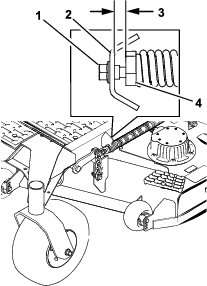
-
Set the gap between the spring adjuster and the bracket to 22 to 29 mm (7/8 to 1-1/8 inches).
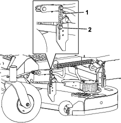
Replacing the Grass Deflector
Danger
An uncovered discharge opening allows objects to be thrown toward you or bystanders. Also, contact with the blade could occur. Thrown objects or blade contact will cause serious injury or death.
Do not operate the mower with the discharge deflector raised, removed, or altered unless a grass collection system or mulch kit is in place and working properly.
-
Remove the locknut, bolt, spring, and spacer holding the deflector to the pivot brackets.
-
Remove the damaged or worn grass deflector.
-
Place the spacer and the spring onto the grass deflector.
-
Place 1 J-hook end of the spring behind the deck edge.
Note: Make sure that 1 J-hook end of spring is installed behind deck edge before installing the bolt as shown in Figure 93.
-
Install the bolt and the nut.
-
Place 1 J-hook end of the spring around the grass deflector.
Important: The grass deflector must be able to rotate. Lift the deflector up to the full open position, and ensure that it rotates into the full-down position.
Cleaning
Cleaning under the Mower Deck
| Maintenance Service Interval | Maintenance Procedure |
|---|---|
| Before each use or daily |
|
Remove the grass buildup under the mower daily.
Important: Do not use water to clean the machine. Water can damage the motors and other electric components. Use compressed air to clean debris from the machine.
Warning
Using compressed air improperly to clean the machine could result in serious injury.
-
Wear appropriate personal protective equipment, such as eye protection, hearing protection, and a dust mask.
-
Do not aim compressed air at any part of your body or at anyone else.
-
Refer to the manufacturer’s instructions for the air compressor for operating and safety information.
-
Park the machine on a level surface, disengage the PTO, and move the motion-control levers outward to the PARK position.
-
Shut off the machine, remove the key, and wait for all moving parts to stop before leaving the operating position.
-
Turn the battery-disconnect switch to the OFF position.
-
Raise the front of the machine and use jack stands to support the mower.
-
Clean debris from the machine using compressed air.
Cleaning the Suspension System
Machines with MyRide™ Suspension System Only

| Maintenance Service Interval | Maintenance Procedure |
|---|---|
| Before each use or daily |
|
Use compressed air to clean the suspension system.
Important: Do not clean the shock assemblies with pressurized water.
Disposing of Waste
Engine oil, batteries, hydraulic fluid, and engine coolant are pollutants to the environment. Dispose of these according to your state and local regulations.
Storage
Cleaning and Storage
| Maintenance Service Interval | Maintenance Procedure |
|---|---|
| Before storage |
|
-
Park the machine on a level surface, disengage the PTO, and move the motion-control levers outward to the PARK position.
-
Shut off the machine, remove the key, and wait for all moving parts to stop before leaving the operating position.
-
Remove grass clippings, dirt, and grime from the external parts of the entire machine using compressed air.
Important: Do not use water to clean the machine, otherwise you could damage the motors and other electric components.
-
Check the brake; refer to Park Position.
-
Grease the machine; refer to Lubrication.
-
Check the tire pressure; refer to Checking the Tire Pressure.
-
Check and tighten all fasteners. Repair or replace any part that is damaged or missing.
-
Paint all scratched or bare metal surfaces with paint from an Authorized Service Dealer.
-
Store the machine in a clean, dry, garage or storage area. Remove the key from the switch and store it in a memorable place. Cover the machine to protect it and keep it clean.
-
For prolonged storage, follow the battery storage requirements; refer to Battery Storage Requirements.
Battery Storage Requirements
Note: You do not need to remove the batteries from the machine for storage.
Refer to the temperature limits for storage in the following table:
| Storage Temperature | Appropriate Storage Time |
| 45° to 55°C (113° to 131°F) | 1 week |
| 25° to 45°C (77° to 113°F) | 3 weeks |
| -20° to 25°C (-4° to 77°F) | 52 weeks |
Important: Temperatures outside of these ranges will damage your batteries.The temperature that the batteries are stored at will affect their long-term life. Storage for long periods of time at extreme temperatures will reduce the battery life. For temperatures above 25°C (77°F), only store the machine for the appropriate amount of time indicated in the table.
-
Before you store the machine, charge or discharge the batteries between 40% to 60% (54.3V to 57.3V).
Note: A 50% charge is optimal to ensure a maximum battery life. When the batteries are charged to 100% before storage, the battery life shortens.If you anticipate that the machine will be stored for a longer period of time, charge the batteries to around 60%.
-
For every 6 months of storage, check the battery-charge level and ensure that it is between 40% to 60%. If the charge is below 40%, charge the batteries between 40% to 60%.
-
You can use a multimeter to check the charge level when the machine is off. Refer to the following table for the amount of voltage that is equal to the charge level:
Voltage Charge Level 57.3V 60% 55.4V 50% 54.3V 40% -
After charging the batteries, disconnect the battery charger from power. Disconnect the power connector during storage to minimize the discharging of the batteries.
-
If you leave the charger on the machine, it will shut off after the batteries are fully charged and does not turn back on unless the charger is disconnected and reconnected.
Storing the Charger
-
Disconnect the power to the machine; refer to Using the Battery-Disconnect Switch.
-
Disconnect the power supply cord from the charger and coil it securely.
-
Examine the power supply cord thoroughly for signs of wear or damage. Replace it if it is worn or damaged.
-
Examine the charger thoroughly for worn, loose, or damaged parts. To repair or replace parts, contact your authorized Toro distributor for assistance.
-
Store the charger with the power supply cord in a clean, dry place where it will not be bumped or damaged and not exposed to caustic fumes.
Troubleshooting
| Problem | Possible Cause | Corrective Action |
|---|---|---|
| The machine does not start or fails to keep running. |
|
|
| The machine pulls to the left or right (with both motion-control levers fully forward). |
|
|
| There is abnormal vibration. |
|
|
| The cutting height is uneven. |
|
|
| The blades do not rotate. |
|
|
| Problem | Possible Cause | Corrective Action |
|---|---|---|
| SPN 4992, FMI 16 or FMI 3 |
|
|
| SPN 4990, FMI 31 |
|
|
| SPN 520196, FMI 16 |
|
|
| SPN 4992, FMI 4 |
|
|
| SPN 520193, FMI 3 |
|
|
| SPN 524032, FMI 3 |
|
|
| SPN 520193, FMI4 |
|
|
| SPN 524033, FMI 31 |
|
|
| SPN 524035 or SPN 524042, FMI 31 |
|
|
| SPN 524035 or SPN 524042, FMI 9 |
|
|

| Problem | Possible Cause | Corrective Action |
|---|---|---|
| SPN 524160, FMI 31 |
|
|
Schematics
Electrical Schematic