

Maintenance
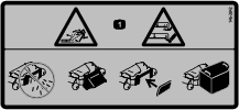
Caution
If you leave the key in the ignition switch, someone could accidently start the engine and seriously injure you or other bystanders.
Remove the key from the ignition and disconnect the wire from the spark plug before you do any maintenance. Set the wire aside so that it does not accidentally contact the spark plug.
Danger
Engines can become hot when they are operating. Severe burns can occur from contacting hot surfaces.
Allow engines, especially the muffler, to cool before touching.
Danger
Debris, such as leaves, grass, or brush can catch fire. A fire in the engine area can cause personal injury and property damage.
-
Keep the engine and muffler area free of debris accumulation.
-
Take care when opening the bagger cover to keep debris from falling onto the engine and muffler area.
-
Allow the machine to cool before storing it.
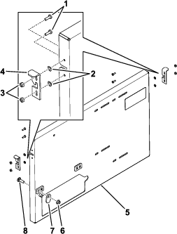
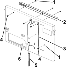
Inspecting the Bagger
| Maintenance Service Interval | Maintenance Procedure |
|---|---|
| After the first 10 hours |
|
| Before storage |
|
-
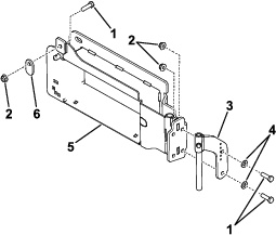
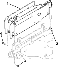
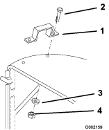
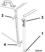
Inspect all the fasteners and latches; replace any that are missing or damaged.
-
Inspect the bag for damage and replace any damaged parts.
-
Tighten all hardware.
Warning
You or bystanders could be severely injured by flying debris or thrown objects that may pass through torn, worn, or deteriorated grass bags.
-
Check the grass bags for holes, rips, wear, and other deterioration.
-
If the bag has deteriorated, install new grass bags supplied by the manufacturer of this bagger attachment.
-
Cleaning the Bagger
| Maintenance Service Interval | Maintenance Procedure |
|---|---|
| Before each use or daily |
|
Clean the bagger after each use.
-
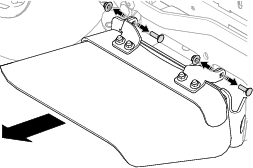
Remove the bag and wash the back plate and the underside of the mower. Use a mild automotive detergent to remove stubborn dirt.
Important: Do not pressure wash the bagger.
-
Remove matted grass from all parts.
-
After washing, let all parts dry thoroughly.
Note: Do not wash the grass bags.
Storing the Grass Catcher
-
Clean the bagger; refer to Cleaning the Bagger.
-
Inspect the bagger for damage; refer to Inspecting the Bagger.
-
Ensure that the bag is empty and dry.
-
Store the bagger in a clean, dry place out of direct sunlight. This extends the life of the bagger. If you must store it outside, cover it with a weatherproof cover.