| Maintenance Service Interval | Maintenance Procedure |
|---|---|
| Before each use or daily |
|
Introduction
This utility vehicle is intended to be primarily used off-highway to transport people and material loads. Using this product for purposes other than its intended use could prove dangerous to you and bystanders.
Read this information carefully to learn how to operate and maintain your product properly and to avoid injury and product damage. You are responsible for operating the product properly and safely.
Visit www.Toro.com for product safety and operation training materials, accessory information, help finding a dealer, or to register your product.
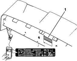
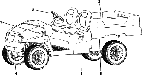
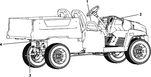
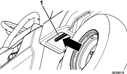
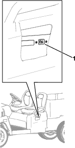
Whenever you need service, genuine Toro parts, or additional information, contact an Authorized Service Distributor or Toro Customer Service and have the model and serial numbers of your product ready. Figure 1 identifies the location of the model and serial numbers on the product. Write the numbers in the space provided.
Important: With your mobile device, you can scan the QR code on the serial number decal (if equipped) to access warranty, parts, and other product information.
This manual uses 2 words to highlight information. Important calls attention to special mechanical information and Note emphasizes general information worthy of special attention.
The safety-alert symbol (Figure 2) appears both in this manual and on the machine to identify important safety messages that you must follow to avoid accidents. This symbol will appear with the word Danger, Warning, or Caution.
-
Danger indicates an imminently hazardous situation which, if not avoided, will result in death or serious injury.
-
Warning indicates a potentially hazardous situation which, if not avoided, could result in death or serious injury.
-
Caution indicates a potentially hazardous situation which, if not avoided, may result in minor or moderate injury.

This product complies with all relevant European directives; for details, please see the separate product specific Declaration of Conformity (DOC) sheet.
Warning
CALIFORNIA
Proposition 65 Warning
The power cord on this product contains lead, a chemical known to the State of California to cause birth defects or other reproductive harm. Wash hands after handling.
Battery posts, terminals, and related accessories contain lead and lead compounds, chemicals known to the State of California to cause cancer and reproductive harm. Wash hands after handling.
Use of this product may cause exposure to chemicals known to the State of California to cause cancer, birth defects, or other reproductive harm.
Safety
General Safety
-
This product is capable of causing personal injury or death. Always follow all safety instructions to avoid serious personal injury.
-
Improper operation, maintenance, or poor housekeeping of the machine may cause it to become unstable; other factors include terrain conditions, slope, speed, and poor operator judgment.
-
Read and understand the contents of this Operator’s Manual before you start the machine. Ensure that everyone using this product knows how to use it and understands the warnings.
-
Use your full attention while operating the machine. Do not engage in any activity that causes distractions; otherwise, injury or property damage may occur.
-
Do not put your hands or feet near moving components of the machine.
-
Do not operate the machine without all guards and other safety protective devices in place and in good working order.
-
Keep bystanders and children out of the operating area. Never allow children to operate the machine.
-
Stop and shut off the machine and remove the key before servicing.
-
Improperly using or maintaining this machine can result in injury. To reduce the potential for injury, comply with these safety instructions and always pay attention to the safety-alert symbol
 , which means Caution, Warning,
or Danger—personal safety instruction. Failure to comply with
these instructions may result in personal injury or death.
, which means Caution, Warning,
or Danger—personal safety instruction. Failure to comply with
these instructions may result in personal injury or death.
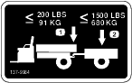
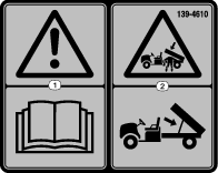
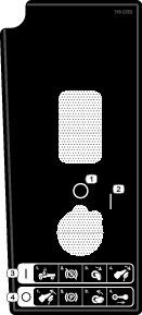
Safety and Instructional Decals
 |
Safety decals and instructions are easily visible to the operator and are located near any area of potential danger. Replace any decal that is damaged or missing. |


Setup
Installing the Steering Wheel
International Models Only
Parts needed for this procedure:
| Steering wheel | 1 |
| Locknut | 1 |
| Wheel cover | 1 |
| Screw | 3 |
-
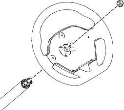
Place the steering wheel on the steering shaft.
Ensure that the steering wheel is centered (i.e., the flat bottom should be parallel with the ground).
-
Use the locknut to secure the steering wheel to the steering shaft.
-
Torque the locknut to 27 N∙m (20 ft-lb).
-
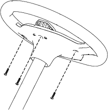
Use 3 screws to secure the wheel cover to the steering wheel.
-
Torque the 3 screws to 0.6 N∙m (5 in-lb).
Charging the Machine
Charge the machine; refer to Understanding the Lithium-Ion Battery Charger.
Checking the Fluid Levels and Tire Pressure
-
Check the brake-fluid level before you first start the machine; refer to Checking the Brake-Fluid Level.
-
Check the transaxle-fluid level before you first start the machine; refer to Checking the Transaxle-Fluid Level.
-
Check the air pressure in the tires; refer to Checking the Tire Pressure.
Burnishing the Brakes
To ensure optimum performance of the brake system, burnish (break-in) the brakes before use.
-
Bring the machine up to full speed, apply the brakes to rapidly stop the machine without locking up the tires.
-
Repeat this procedure 10 times, waiting 1 minute between stops, to avoid overheating the brakes.
Important: This procedure is most effective if the machine is loaded with 227 kg (500 lb).
Reading the Manual and Viewing the Setup Material
Parts needed for this procedure:
| Operator's Manual | 1 |
| Registration card | 1 |
| Predelivery Inspection Form | 1 |
| Certificate of Quality | 1 |
| Key | 2 |
-
Read the Operator's Manual.
-
Fill out the registration card.
-
Complete the Predelivery Inspection Form.
-
Review the Certificate of Quality.
Product Overview
Control Panel
Accelerator Pedal
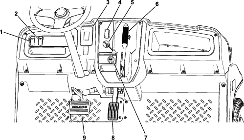
Use the accelerator pedal (Figure 7) to vary ground speed of the machine. Pressing down the accelerator pedal starts the machine. Pressing the pedal farther increases ground speed. Releasing the pedal slows the machine, and the machine shuts off.
The maximum forward speed in performance mode is 26 km/h (16 mph) as shown in Figure 18.
The maximum forward speed in economy mode is 19 km/h (12 mph) as shown in Figure 18.
Brake Pedal
Use the brake pedal to stop or slow the machine.
Warning
Operating a machine with worn or incorrectly adjusted brakes can result in personal injury.
If the brake pedal travels within 25 mm (1 inch) of the machine floor board, adjust or repair the brakes.
Parking-Brake Lever
The parking-brake lever is located on the control panel (Figure 7).
Whenever you shut off the machine, engage the parking brake to prevent the machine from accidentally moving. If the machine is parked on a steep grade, ensure that you engage the parking brake.
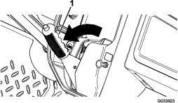
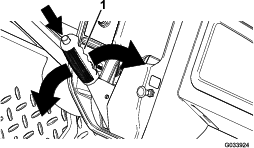
To engage the parking brake, pull the parking-brake lever toward you (Figure 8).
To disengage the parking brake, push down the button on top of the parking-brake lever, pull the parking-brake lever toward you to release pressure, and then push the parking-brake lever forward (Figure 9).
Direction Selector
The direction selector is located to the left of the parking-brake lever. The direction selector has 2 positions: FORWARD andREVERSE (Figure 7).
Important: Always stop the machine before changing direction.
Horn Switch
The horn switch is located on the control panel (Figure 7). Press the horn switch to sound the horn.
Light Switch
Use the light switch (Figure 7) to illuminate the headlights. Push the light switch up to turn on the headlights. Push the light switch down to turn off the lights.
USB Port
Use the USB port (Figure 7) to power mobile devices.
Important: When you are not using the USB port, insert the rubber plug to prevent damage to the port.
Key Switch
Use the key switch (Figure 7), to run and shut off the machine.
The key switch has 2 positions: ON and OFF. Rotate the key clockwise to the ON position to operate the machine. When you stop the machine, rotate the key counterclockwise to the OFF position to shut off the machine. Remove the key whenever you leave the machine.
Display
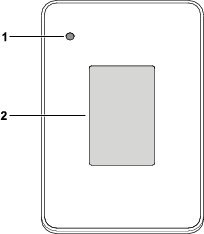
The display shows information about your machine, such as the operating status, various diagnostics, and other information about the machine (Figure 10).
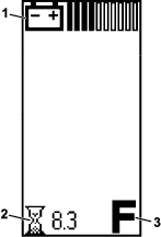
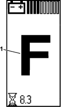
There is a startup screen, run screen, and charging screen on the display (Figure 11, Figure 12, and Figure 13).
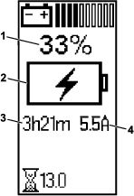
Figure 12 shows what you may see on the display when you run the machine. The startup screen displays for a few seconds after you turn the key to the ON position, then the run screen displays.

The run screen with the direction position (Figure 14) appears when you change directions.
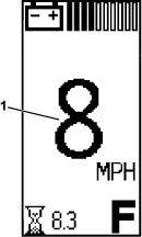
The run screen with the current machine speed (Figure 15) appears when you are driving the machine.
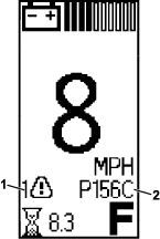
An active fault code (Figure 16) appears on the display if there is an issue with the machine.
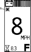
When the cold battery indicator (Figure 17) appears, the machine performance changes until the battery temperature is above 0°C (32°F).
Icon Descriptions
 | Direction—FORWARD position |
 | Direction—REVERSE position |
 | Parking brake is engaged. |
 | Hour meter |
 | Battery voltage |
 | Battery charge level |
 |
Battery currently charging |
 |
Low-battery advisory |
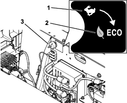
 | Eco Mode is on. |
 | Active fault |
 | Hot battery indicator—battery temperature is greater than 67°C (152°F) |
 | Cold battery indicator—battery temperature is less than 0°C (32°F) |
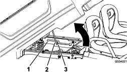
Supervisor Speed-Limit Switch
The supervisor speed-limit switch, located under the seat assembly, has 2 positions: PERFORMANCE and ECONOMY. Rotate the switch clockwise to the ECONOMY position to limit the maximum machine speed to 19 km/h (12 mph). Rotate the switch counterclockwise to the PERFORMANCE position to restore the maximum speed of the machine to 26 km/h (16 mph) as shown in Figure 18.
Passenger Handholds
The passenger handholds are located on the outside of each seat (Figure 19).
Note: Specifications and design are subject to change without notice.
| Base weight | 445 kg (980 lb) |
| Rated capacity (on level ground) | 544 kg (1,200 lb) total, including 91 kg (200 lb) operator and 91 kg (200 lb) passenger, load, accessories, and attachments |
| Gross vehicle weight (GVW)—on level ground | 988 kg (2,180 lb) total, including all of the weights listed above |
| Maximum cargo capacity (on level ground) | 363 kg (800 lb) total, including rear-mounted accessories |
| Maximum rear cargo bed accessory mount capacity | 45 kg (100 lb) total |
| Tow capacity | Tongue weight: 91 kg (200 lb) |
| Gross trailer weight (GTW): 680 kg (1,500 lb) | |
| Overall width | 119 cm (47 inches) |
| Overall length | 302 cm (119 inches) |
| Overall height | 127.5 cm (50-3/16 inches) |
| Ground clearance | 21.6 cm (8-1/2 inches) at the front with no load or operator |
| 14 cm (5-1/2 inch) at the rear with no load or operator | |
| Wheel base | 220 cm (86-5/8 inches) |
| Wheel tread (center line to center line) | Front: 119 cm (47 inches) |
| Rear: 119 cm (47 inches) | |
| Cargo bed length | Inside: 102 cm (40 inches) |
| Outside: 114.3 cm (45 inches) | |
| Cargo bed width | Inside: 98 cm (38-1/2 inches) |
| Outside of the molded fenders: 107.3 cm (42-5/16 inches) | |
| Cargo bed height | 28 cm (11 inches) inside |
Attachments/Accessories
A selection of Toro approved attachments and accessories is available for use with the machine to enhance and expand its capabilities. Contact your Authorized Service Dealer or authorized Toro distributor or go to www.Toro.com for a list of all approved attachments and accessories.
To ensure optimum performance and continued safety certification of the machine, use only genuine Toro replacement parts and accessories. Replacement parts and accessories made by other manufacturers could be dangerous, and such use could void the product warranty.
Operation
Note: The procedures in this section show a machine with a plastic cargo bed and bucket seat; for additional procedures for other attachments, refer to the Operation section (if applicable) in the Installation Instructions. Visit www.Toro.com for your instructions or scan the QR code (if applicable) on your attachment.
Before Operation
Before Operation Safety
General Safety
-
Never allow children or people who are not trained or physically capable to safely operate or service the machine. Local regulations may restrict the age of the operator. The owner is responsible for training all operators and mechanics.
-
Become familiar with the safe operation of the equipment, operator controls, and safety signs.
-
Shut off the machine, remove the key, and wait for all movement to stop before you leave the operator’s position. Allow the machine to cool before adjusting, servicing, cleaning, or storing it.
-
Know how to stop and shut off the machine quickly.
-
Ensure that there are not more occupants (you and your passenger(s)) than the number of handholds equipped on the machine.
-
Check that all safety devices and decals are in place. Repair or replace all safety devices and replace all illegible or missing decals. Do not operate the machine unless they are present and functioning properly.
Performing Daily Maintenance
Before starting the machine each day, perform the Each Use/Daily procedures listed in .
Checking the Tire Pressure
| Maintenance Service Interval | Maintenance Procedure |
|---|---|
| Before each use or daily |
|
Front and rear tires air pressure specification: 165 to 207 kPa (24 to 30 psi)
Important: Do not exceed the maximum air pressure indicated on the sidewall of the tire.
Note: The air pressure needed in the tires is determined by the payload that you intend to carry.
-
Check the air pressure in the tires.
-
Use lower air pressure in the tires for lighter payloads, for less soil compaction, for a smoother ride, and to minimize tire marks on the ground.
-
Use higher air pressure in the tires for carrying heavier payloads at higher speeds.
-
-
If necessary, adjust the air pressure in the tires by adding or removing air in the tires.
Breaking in a New Machine
| Maintenance Service Interval | Maintenance Procedure |
|---|---|
| After the first 100 hours |
|
Perform the breaking in a new machine guidelines to provide proper performance and long life for the machine.
-
Check the brake fluid.
-
Avoid hard braking situations for the first several hours of new machine break-in operation. New brake linings may not be at optimum performance until several hours of use has caused the brakes to become burnished (broken-in).
-
Refer to for any special low hour checks.
-
Check the front suspension positioning and adjust it, if necessary; refer to Adjusting the Wheel Alignment.
-
For optimal battery performance and battery life, charge the batteries to 100% when you receive your machine.
During Operation
During Operation Safety
General Safety
-
The owner/operator can prevent and is responsible for accidents that may cause personal injury or property damage.
-
Passengers should sit in the designated seating positions only. Do not carry passengers in the cargo bed. Keep bystanders and pets away from the machine during operation.
-
Wear appropriate clothing, including eye protection; long pants; substantial, and slip-resistant footwear. Tie back long hair and do not wear loose clothing or loose jewelry.
-
Use your full attention while operating the machine. Do not engage in any activity that causes distractions; otherwise, injury or property damage may occur.
-
Do not operate the machine while ill, tired, or under the influence of alcohol or drugs.
-
Do not exceed the maximum gross vehicle weight (GVW) of the machine.
-
Use extra caution when operating, braking, or turning the machine with a heavy load in the cargo bed.
-
Carrying oversized loads in the cargo bed reduces the stability of the machine. Do not exceed the carrying capacity of the bed.
-
Carrying material that cannot be bound to the machine adversely affects the steering, braking, and stability of the machine. When you carry material that cannot be bound to the machine, use caution when steering or braking.
-
Carry a reduced load and reduce the ground speed of the machine when operating on rough, uneven terrain, and near curbs, holes, and other sudden changes in terrain. Loads may shift, causing the machine to become unstable.
-
Before you start the machine, ensure that the transmission is in neutral, the parking brake is engaged, and you are in the operating position.
-
You and your passengers should remain seated whenever the machine is moving. Keep your hands on the steering wheel; your passengers should use the handholds provided. Keep arms and legs within the machine body at all times.
-
Operate the machine only in good visibility. Watch for holes, ruts, bumps, rocks, or other hidden objects. Uneven terrain could overturn the machine. Tall grass can hide obstacles. Use care when approaching blind corners, shrubs, trees, or other objects that may obscure your vision.
-
Do not drive the machine near drop-offs, ditches, or embankments. The machine could suddenly roll over if a wheel goes over the edge or if the edge gives way.
-
Always watch out for and avoid low overhangs such as tree limbs, door jambs, overhead walkways, etc.
-
Look behind and down before reversing the machine to be sure of a clear path.
-
When using the machine on public roads, follow all traffic regulations and use any additional accessories that may be required by law, such as lights, turn signals, slow-moving vehicle (SMV) signs, and others as required.
-
If the machine ever vibrates abnormally, stop and shut off the machine immediately, wait for all movement to stop, and inspect for damage. Repair all damage to the machine before resuming operation.
-
It can take longer to stop the machine on wet surfaces than on dry surfaces. To dry out wet brakes, drive slowly on level ground while putting light pressure on the brake pedal.
-
Operating the machine at high speed and then quickly stopping may cause the rear wheels to lock up, which impairs your control of the machine.
-
Do not touch the motor while the motor is running, or soon after you turn off the motor, because these areas may be hot enough to cause burns.
-
Do not leave a running machine unattended.
-
Before you leave the operating position, do the following:
-
Park the machine on a level surface.
-
Engage the parking brake.
-
Shut off the machine and remove the key.
-
Wait for all movement to stop.
-
-
Do not operate the machine when there is the risk of lightning.
-
Use accessories and attachments approved by The Toro® Company only.
Multi-Passenger Safety
-
Do not exceed the gross vehicle weight (GVW) of the machine. You must account for yourself, your passengers, and the load in the cargo bed contributing to the overall GVW of the machine.
-
Passengers should sit in the designated seating positions only. Do not allow passengers to sit in the cargo bed.
-
You and your passengers should remain seated whenever the machine is in motion.
-
The additional machine length results in a larger turn radius, so allow more space to maneuver the machine.
Slope Safety
Note: A 2-post Rollover Protection System (ROPS) is available for this machine as an accessory. Use a ROPS if you will work next to drop-offs, near water, in rough terrain, or on a slope, which could result in a rollover. Contact an authorized Toro distributor for more information.
Slopes are a major factor related to loss-of-control and tip-over accidents, which can result in severe injury or death.
-
Survey the site to determine which slopes are safe for operating the machine and establish your own procedures and rules for operating on those slopes. Always use common sense and good judgment when performing this survey.
-
If you feel uneasy operating the machine on a slope, do not do it.
-
Keep all movement on slopes slow and gradual. Do not suddenly change the speed or direction of the machine.
-
Avoid operating the machine on wet terrain. Tires may lose traction. A rollover can occur before the tires lose traction.
-
Travel straight up and down a slope.
-
If you begin to lose momentum while climbing a slope, gradually engage the brakes and slowly reverse the machine straight down the slope.
-
Turning while going up or down a slope can be dangerous. If you must turn on a slope, do it slowly and cautiously.
-
Heavy loads affect stability on a slope. Carry a reduced load and reduce your ground speed when operating on a slope or if the load has a high center of gravity. Secure the load to the cargo bed of the machine to prevent the load from shifting. Take extra care when hauling loads that shift easily (e.g., liquids, rock, sand, etc.).
-
Avoid starting, stopping, or turning the machine on a slope, especially with a load. Stopping while going down a slope takes longer than stopping on level ground. If you must stop the machine, avoid sudden speed changes, which can cause the machine to tip or roll over. Do not engage the brakes suddenly when rolling rearward, as this may cause the machine to overturn.
Loading and Dumping Safety
-
Do not exceed the gross vehicle weight (GVW) of the machine when operating it with a load in the cargo bed and/or towing a trailer; refer to Specifications.
-
Distribute the load in the cargo bed evenly to improve the stability and control of the machine.
-
Before dumping, ensure that there is no one behind the machine.
-
Do not dump a loaded cargo bed while the machine is sideways on a slope. The change in weight distribution may cause the machine to overturn.
Operating the Cargo Bed
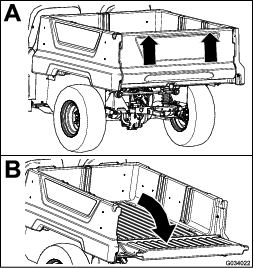
Raising the Cargo Bed to the Dump Position
Warning
A raised bed could fall and injure persons that are working beneath it.
-
Always use the prop rod to hold the bed up before working under the bed.
-
Remove any load material from the bed before raising it.
Warning
Driving the machine with the cargo bed raised could cause the machine to tip or roll easier. You could damage the structure of the cargo bed if you operate the machine with the bed raised.
-
Operate the machine when the cargo bed is down.
-
After emptying the cargo bed, lower it.
Caution
If a load is concentrated near the back of the cargo bed when you release the latches, the bed may unexpectedly tip open, injuring you or bystanders.
-
Center loads in the cargo bed, if possible.
-
Hold the cargo bed down and ensure that no one is leaning over the bed or standing behind it when releasing the latches.
-
Remove all cargo from the bed before lifting the bed up to service the machine.
Raising the Cargo Bed to the Service Position
Lowering the Cargo Bed
Warning
The weight of the bed may be heavy. Hands or other body parts could be crushed.
Keep your hands and other body parts away when lowering the bed.
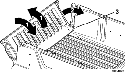
Opening the Tailgate
Closing the Tailgate
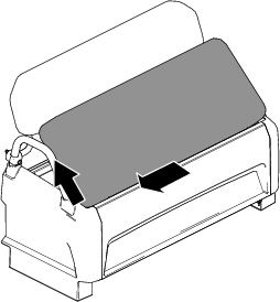
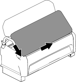
If you unloaded loose material such as sand, landscaping rock, or wood chips from the cargo bed of the machine, some of the material that you unloaded may have lodged in the hinge area of the tailgate. Perform the following steps before closing the tailgate.
-
Use your hands to remove as much of the material from the hinge area as possible.
-
Rotate the tailgate to approximately the 45° position (Figure 24).
-
Use a short, shaking motion to rotate the tailgate back and forth several times (Figure 24).
Note: This action helps move material away from the hinge area.
-
Lower the tailgate and check for material remaining in the hinge area.
-
Repeat steps 1 through 4 until the material is removed from the hinge area.
-
Rotate the tailgate up and lift the tailgate into the notches in the cargo bed.
Monitoring the Battery-System Charge Level
Refer to the display to determine the battery-system charge level; refer to Display.
Understanding the Low Battery-Level Advisories
If the battery level becomes too low (i.e., below 10%), a low-battery icon appears on the display. When you are operating at this battery percentage, drive the machine to a designated battery-charging area and charge the batteries; refer to Charging the Lithium-Ion Batteries.
If you operate the machine while the battery charge level is blank, the machines operates at a reduced speed (i.e., 5 km/h or 3 mph).
Stopping the Machine
Important: When stopping the machine on an incline, use the service brakes to stop the machine and engage the parking brake to hold the machine in place. Using the accelerator to stall the machine on the hill can overheat the motor or drain the batteries.
-
Remove your foot from the accelerator pedal.
-
Slowly press the brake pedal to apply the service brakes until the machine comes to a complete stop.
Note: The stopping distance may vary depending on the machine load and speed.
Loading the Cargo Bed
Use the following guidelines when loading the cargo bed and operating the machine:
-
Observe the weight capacity of the machine and limit the weight of the load that you carry in the cargo bed as described in Specifications and on the gross vehicle weight tag of the machine.
Note: The load rating is specified for machine operation on a level surface only.
-
Reduce the weight of the load that you carry in the cargo bed when operating the machine on hills and rough terrain.
-
Reduce the weight of the load that you carry when the materials are tall (and have a high center of gravity), such as a stack of bricks, landscaping timbers, or fertilizer bags. Distribute the load as low as possible to ensure that the load does not reduce your ability to see behind the machine when operating it.
-
Keep loads centered by loading the cargo bed as follows:
-
Evenly position the weight in the cargo bed from side to side.
Important: Tipping over is more likely to occur if the cargo bed is loaded to 1 side.
-
Evenly position the weight in the cargo bed from front to back.
Important: Loss of steering control or the machine may tip over if you position the load behind the rear axle and the traction on the front tires is reduced.
-
-
Use extra caution when transporting oversized loads in the cargo bed, particularly when you cannot center the weight of the oversize load to the cargo bed.
-
Whenever possible, secure the load by binding it to the cargo bed so that it does not shift.
-
When transporting liquids, use caution when driving the machine uphill or downhill, when suddenly changing speed or stopping, or when driving over rough surfaces.
The capacity of the cargo bed is 0.28 m3 (10 ft3). The amount (volume) of material that you can place in the bed without exceeding the load ratings of the machine can vary greatly depending on the density of the material.
Refer to the following table for load volume limits with various materials:
| Material | Density | Maximum Cargo Bed Capacity(on level ground) |
| Gravel, dry | 1522 kg/m3 (95 lb/ft3) | Full |
| Gravel, wet | 1922 kg/m3 (120 lb/ft3) | 3/4 Full |
| Sand, dry | 1442 kg/m3 (90 lb/ft3) | Full |
| Sand, wet | 1922 kg/m3 (120 lb/ft3) | 3/4 Full |
| Wood | 721 kg/m3 (45 lb/ft3) | Full |
| Bark | <721 kg/m3 (<45 lb/ft3) | Full |
| Earth, packed | 1602 kg/m3 (100 lb/ft3) | 3/4 Full (approximately) |
After Operation
After Operation Safety
General Safety
-
Before you leave the operating position, do the following:
-
Park the machine on a level surface.
-
Engage the parking brake.
-
Shut off the machine and remove the key.
-
Wait for all movement to stop.
-
-
Allow the machine to cool before adjusting, servicing, cleaning, or storing it.
-
Do not store the machine where there is an open flame, spark, or pilot light, such as on a water heater or other appliance.
-
Keep all parts of the machine in good working condition and all hardware tightened.
-
Maintain and clean the seat belt(s) as necessary.
-
Replace all worn, damaged, or missing decals.
Battery and Charger Safety
General
-
WARNING: Risk of fire and electric shock—The batteries have no user-serviceable parts.
-
Confirm the voltage that is available in your country before using the charger.
-
Do not get the charger wet; keep it protected from rain and snow.
-
A risk of fire, electric shock, or injury may result from using an accessory not recommended or sold by Toro.
-
To reduce risk of a battery explosion, follow these instructions and the instructions for any equipment that you intend to use near the charger.
-
Batteries could emit explosive gasses if they are significantly overcharged.
-
Refer to an authorized Toro distributor to service or replace a battery.
Training
-
Never allow children or untrained people to operate or service the charger. Local regulations may restrict the age of the operator. The owner is responsible for training all operators and mechanics.
-
Read, understand, and follow all instructions on the charger and in the manual before operating the charger. Be familiar with the proper use of the charger.
Preparation
-
Keep bystanders and children away while charging.
-
Wear appropriate clothing while charging, including eye protection; long pants; and substantial, slip-resistant footwear.
-
Shut off the machine and wait until the machine has completely powered down before charging. Failure to do this may cause arcing.
-
Ensure that the area is well ventilated while charging.
-
The charger is for use on only nominal 120 to 240 VAC operation. For use with 240 V circuits, contact your authorized Toro distributor for the correct power cord.
Operation
-
Do not charge a frozen battery.
-
Do not abuse the cord. Do not carry the charger by the cord or yank on the power supply cord to disconnect the charger from the receptacle. Keep the cord from heat, oil, and sharp edges.
-
Connect the charger directly to a grounding receptacle. Do not use the charger on an ungrounded outlet, even with a grounding adapter.
-
Do not alter the provided power cord or plug.
-
Remove metal items such as rings, bracelets, necklaces, and watches when working with a lithium-ion battery. A lithium-ion battery can produce enough current to cause a severe burn.
-
Never operate the charger without good visibility or light.
-
Use an extension cord capable of handling 15 A or more. If you are charging outdoors, use an extension cord rated for outdoor use.
-
If the power supply cord is damaged while it is plugged in, disconnect the cord from the wall receptacle and contact an authorized Toro distributor for a replacement.
-
Unplug the charger from the electrical outlet when not in use, before moving it to another location, or prior to servicing it.
Maintenance and Storage
-
Store the charger indoors in a dry, secure place that is out of the reach of unauthorized users.
-
Do not disassemble the charger. Take the charger to an authorized Toro distributor when service or repair is required.
-
Unplug the power cord from the outlet before starting any maintenance or cleaning to reduce risk of electric shock.
-
Maintain or replace safety and instruction labels as needed.
-
Do not operate the charger with a damaged cord or plug. Contact an authorized Toro distributor to obtain a replacement cord.
-
If the charger has received an impact, been dropped, or otherwise damaged, do not use it; take it to an authorized Toro distributor.
Hauling the Machine
-
Use care when loading or unloading the machine into a trailer or a truck.
-
Use full-width ramps for loading the machine into a trailer or a truck.
-
Tie the machine down securely.
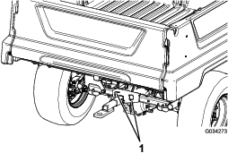
Refer to Figure 25 and Figure 26 for the tie-down locations on the machine.
Note: Load the machine on the trailer with the front of the machine facing forward. If that is not possible, secure the machine hood to the frame with a strap, or remove the hood and transport and secure it separately or the hood may blow off during transport.
Caution
Loose seats may fall off the machine and trailer when transporting the machine, and the seats may land on another machine or obstruct the roadway.
Remove the seats or ensure that the seats are secured by the pivot pins.
Towing the Machine
In case of an emergency, you can tow the machine for a short distance; however, this should not be a standard operating procedure.
Warning
Towing at excessive speeds could cause a loss of steering control, resulting in personal injury.
Never tow the machine at faster than 8 km/h (5 mph).
Towing the machine is a 2-person job. If you must move the machine a considerable distance, transport it on a truck or trailer; refer to Towing a Trailer.
-
Shut off the machine and remove the key.
Important: If you tow the machine with the key in the ON position, the electrical system may be damaged.
-
Affix a tow line to the tongue at the front of the machine frame (Figure 25).
-
Disengage the parking brake.
Towing a Trailer
The machine is capable of pulling trailers. Tow hitches are available for the machine, contact your authorized Toro distibutor for details.
When hauling cargo or towing a trailer, do not overload your machine or trailer. Overloading either the machine or the trailer can cause poor performance or damage to the brakes, axle, motor, transaxle, steering, suspension, body structure, or tires.
Always load a trailer with 60% of the cargo weight in the front of the trailer. This places approximately 10% of the gross trailer weight (GTW) on the tow hitch of the machine.
To provide adequate braking and traction, always load the cargo bed when using a trailer. Do not exceed the GTW or GVW limits.
Avoid parking a machine with a trailer on a hill. If you must park on a hill, engage the parking brake and block the tires of the trailer.
Transporting the Lithium-Ion Batteries
The US Department of Transportation and international transportation authorities require that lithium-ion batteries be transported using special packaging and only be transported by carriers certified to haul them. In the US, you are allowed to transport a battery when it is installed on the machine as battery powered equipment, with some regulatory requirements. Contact the US Department of Transportation or the appropriate government body in your country for detailed regulations on transportation of your batteries or the machine with the batteries equipped.
For detailed information on shipping a battery, contact your authorized Toro distributor.
Understanding the Lithium-Ion Battery Charger
Connecting to a Power Source
Danger
Contact with water while charging the machine could cause electric shock, causing injury or death.
-
Do not handle the plug or the charger with wet hands or while standing in water.
-
Do not charge the batteries in the rain or in wet conditions.
To reduce the risk of electric shock, this charger has a 3-prong grounded plug (type B). If the plug does not fit into the wall receptacle, other grounded plug types are available; contact an authorized Toro distributor.
Do not change the charger or the power-supply-cord plug in any way.
Important: Check the power supply cord periodically for holes or cracks in the insulation. Do not use a damaged cord. Do not run the cord through standing water or wet grass.
See Figure 27 for power source requirements.
-
Plug the power-supply cord into the machine charger outlet (Figure 28).
Warning
A damaged charger cord can cause an electrical shock or a fire.
Thoroughly inspect the power supply cord before using the charger. If the cord is damaged, do not operate the charger until you obtain a replacement.
-
Insert the wall plug end of the power-supply cord into a grounded electrical outlet.
Charging the Lithium-Ion Batteries
Caution
Attempting to charge the batteries with a charger not provided by Toro can result in excessive heat and other related product malfunctions, which can lead to property damage and/or injury.
Use the Toro-provided chargers to charge the batteries.
Recommended temperature range for charging: 0° to 45°C (32° to 113°F)
Important: Charge the batteries only in temperatures that are within the recommended range.
Note: The charger will not function in temperatures exceeding the minimum or maximum temperatures. The hot or cold battery indicators will appear on the display.
The charging status is shown on the display.
If there is a fault, an error message will appear in the display. To correct an error, refer to the machine Service Manual.
Completing the Charging Process
-
Remove the power-supply cord from the machine charger outlet.
-
Place the cord in a storage position that avoids damage.
-
Turn on the machine.
-
Verify the charge level; refer to Monitoring the Battery-System Charge Level.
Maintenance
Note: The procedures in this section show a machine with a plastic cargo bed and bucket seat; for additional procedures for other attachments, refer to the Maintenance section (if applicable) in the Installation Instructions. Visit www.Toro.com for your instructions or scan the QR code (if applicable) on your attachment.
Maintenance Safety
-
Do not allow untrained personnel to service the machine.
-
Before you leave the operating position, do the following:
-
Park the machine on a level surface.
-
Engage the parking brake.
-
Shut off the machine and remove the key.
-
Wait for all movement to stop.
-
-
Allow the machine to cool before adjusting, servicing, cleaning, or storing it.
-
Support the machine with jack stands whenever you work under the machine.
-
Do not work under a raised bed without the proper bed safety support in place.
-
Do not charge the batteries while servicing the machine.
-
To ensure that the entire machine is in good condition, keep all hardware properly tightened.
-
To reduce the potential fire hazard, keep the machine area free of excessive grease, grass, leaves, and accumulation of dirt.
-
If possible, do not perform maintenance while the machine is running. Keep away from moving parts.
-
If you must run the machine to perform a maintenance adjustment, keep your hands, feet, clothing, and any parts of the body away from any moving parts. Keep bystanders away from the machine.
-
Check the parking brake operation as recommended in the maintenance schedule and adjust and service it as required.
-
Keep all parts of the machine in good working condition and all the hardware properly tightened. Replace all worn or damaged decals.
-
Never interfere with the intended function of a safety device or reduce the protection provided by a safety device.
-
If major repairs are ever necessary or assistance is required, contact an authorized Toro distributor.
-
Altering this machine in any manner may affect the operation of the machine, performance, durability, or its use may result in injury or death. Such use could void the product warranty of The Toro® Company.
Recommended Maintenance Schedule(s)
| Maintenance Service Interval | Maintenance Procedure |
|---|---|
| After the first 100 hours |
|
| Before each use or daily |
|
| Every 100 hours |
|
| Every 300 hours |
|
| Every 400 hours |
|
| Every 800 hours |
|
| Every 1,000 hours |
|
Note: Download a free copy of the electrical schematic by visiting www.Toro.com and searching for your machine from the Manuals link on the home page.
Warning
Failure to properly maintain the machine could result in premature failure of machine systems, causing possible harm to you or bystanders.
Keep the machine well maintained and in good working order as indicated in these instructions.
Maintaining the Machine under Special Operating Conditions
Important: If the machine is subjected to any of the conditions listed below, perform maintenance twice as frequently:
-
Desert operation
-
Cold climate operation—below 10°C (50°F)
-
Trailer towing
-
Frequent operation in dusty conditions
-
Construction work
-
After extended operation in mud, sand, water, or similar dirty conditions, do the following:
-
Have your brakes inspected and cleaned as soon as possible. This prevents any abrasive material from causing excessive wear.
-
Wash the machine using water alone or with a mild detergent.
Important: Do not use brackish or reclaimed water to clean the machine.
-
Pre-Maintenance Procedures
Warning
Raise the cargo bed before performing maintenance. A raised cargo bed can fall and injure persons that are underneath it.
-
Always use the prop rod to hold the cargo bed up before working underneath it.
-
Remove any load material from the cargo bed before working underneath it.
Preparing the Machine for Maintenance
-
Park the machine on a level surface.
-
Engage the parking brake.
-
Shut off the machine and remove the key.
-
Empty and raise the cargo bed.
Lifting the Machine
Danger
The machine may be unstable when using a jack. The machine could slip off the jack, injuring anyone beneath it.
-
Do not start the machine while the machine is on a jack.
-
Always remove the key from the key switch before getting off the machine.
-
Block the tires when the machine is supported by lifting equipment.
-
Use jack stands to support the machine once you have lifted it.
Important: Whenever you run the machine for routine maintenance and/or diagnostics, ensure that the rear wheels of the machine are 25 mm (1 inch) off the ground, with the rear axle supported on jack stands.
-
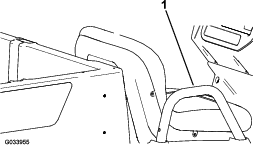
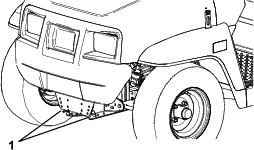
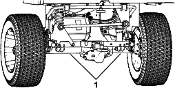
The lifting point at the front of the machine is located at the front of the frame, behind the towing tongue (Figure 29).
-
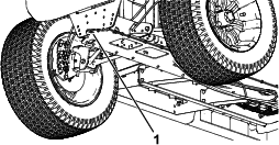
The lifting point at the rear of the machine is located under the axle tubes (Figure 30).
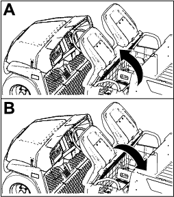
Accessing the Hood
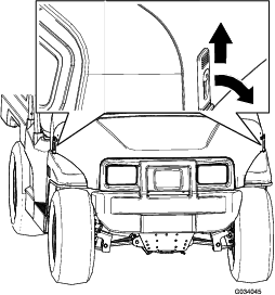
Raising and Lowering the Seat Assembly
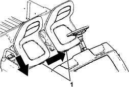
Removing a Bucket Seat
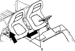
Installing a Bucket Seat
Slide the seat assembly onto the pins and lower the seat assembly (Figure 34).
Removing a Bench Cushion
-
Push the bench cushion forward to the raised position.
-
Slide the cushion to the side, out of the pins, and lift the cushion upward (Figure 35).
Installing a Bench Cushion
Slide the bench cushion onto the pins and lower the cushion (Figure 36).
Lubrication
Greasing the Front Wheel Bearings
| Maintenance Service Interval | Maintenance Procedure |
|---|---|
| Every 300 hours |
|
Grease specification: Mobilgrease XHP™-222
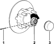
Removing the Hub and Rotor
-
Lift the front of the machine and support it with jack stands.
-
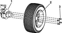
Remove the 4 lug nuts that secure the wheel to the hub (Figure 37).
-
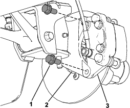
Remove the flange-head bolts (3/8 x 3/4 inch) that secure the bracket for the brake assembly to the spindle and separate the brake from the spindle (Figure 38).
Note: Support the brake assembly before proceeding to the next step.
-
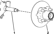
Remove the dust cap from the hub (Figure 39).
-
Remove the cotter pin and nut retainer from the spindle and spindle nut (Figure 39).
-
Remove the spindle nut from the spindle, and separate the hub and rotor assembly from the spindle (Figure 39 and Figure 40).
-
Wipe clean the spindle with a rag.
-
Repeat steps 1 through 7 to the hub and rotor at the other side of the machine.
Greasing the Wheel Bearings
-
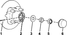
Remove the outboard bearing and bearing race from the hub (Figure 41).
-
Remove the seal, inboard bearing from the hub (Figure 41).
-
Wipe clean the seal and check for wear and damage.
Note: Do not use cleaning solvent to clean the seal. Replace the seal if it is worn or damaged.
-
Clean the bearings and races, and check these parts for wear and damage.
Note: Replace all worn or damaged parts. Ensure that the bearings and races are clean and dry.
-
Clean the cavity of the hub of all grease, dirt, and debris (Figure 41).
-
Pack the bearings with the specified grease.
-
Fill the cavity of hub 50 to 80% full of the specified grease (Figure 41).
-
Assemble the inboard bearing onto the race at the inboard side of the hub and install the seal (Figure 41).
-
Repeat steps 1 through 8 to the bearings for the other hub.
Installing the Hub and Rotor
-
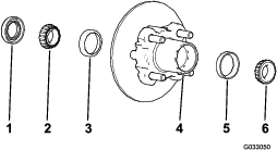
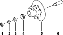
Apply a light coat of the specified grease to the spindle (Figure 42).
-
Assemble the hub and rotor onto the spindle with the rotor inboard (Figure 42).
-
Assemble the outboard bearing onto the spindle and seat the bearing to the outboard race (Figure 42).
-
Assemble the tab washer onto the spindle (Figure 42).
-
Thread the spindle nut onto the spindle and tighten the nut to 15 N∙m (11 ft-lb), while rotating the hub to seat the bearing (Figure 42).
-
Loosen the spindle nut until the hub rotates freely.
-
Torque the spindle nut to 170 to 225 N∙cm (15 to 20 in-lb).
-
Install the retainer over the nut and check the alignment of the slot in the retainer and the hole in the spindle for the cotter pin (Figure 43).
Note: If the slot in the retainer and the hole in the spindle are not aligned, tighten the spindle nut to align the slot and hole to a maximum torque of 226 N∙cm (20 in-lb) on the nut.
-
Install the cotter pin and bend each legs around the retainer (Figure 43).
-
Install the dust cap onto the hub (Figure 43).
-
Repeat steps 1 through 10 for the hub and rotor at the other side of the machine.
Installing the Brakes and Wheels
-
Clean the 2 flange-head bolts (3/8 x 3/4 inch) and apply a coat of medium-strength thread-locking compound to the threads of the bolts.
-
Align the brake pads to either side of the rotor (Figure 38) and the holes in the caliper bracket with the holes in the brake mount of the spindle frame (Figure 42).
-
Secure the caliper bracket to the spindle frame (Figure 38) using the 2 flange-head bolts (3/8 x 3/4 inch).
Torque the 2 flange-head bolts to 47 to 54 N∙m (35 to 40 ft-lb).
-
Align the holes in the wheel to the studs of the hub and assemble the wheel to the hub with the valve stem outward (Figure 37).
Note: Ensure that the mounting surface of the wheel is flush with the hub.
-
Secure the wheel to the hub using the lug nuts (Figure 37).
Torque the lug nuts to 108 to 122 N∙m (80 to 90 ft-lb).
-
Repeat steps 1 through 5 for the brake and wheel on the other side of the machine.
Electrical System Maintenance
Electrical System Safety
-
Unplug the power cord before connecting or disconnecting the battery.
-
Wear protective clothing and use insulated tools. Disconnect the battery before repairing the machine. Disconnect the negative terminal first and the positive last. Connect the positive terminal first and the negative last.
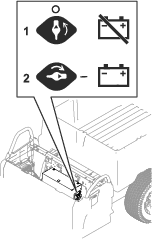
Using the Battery-Disconnect Switch
-
Unplug the power cord to the battery charger if it is connected.
-
Remove or flip up the seat assembly.
-
Move the battery-disconnect switch to the desired position as shown in Figure 44.
Servicing the Batteries
Note: The machine is equipped with at least 2 lithium-ion batteries.
A lithium-ion battery must be disposed of or recycled in accordance with local and federal regulations. If a battery requires service, contact your authorized Toro distributor for assistance.
Do not open the battery. If you are having problems with a battery, contact your authorized Toro distributor for assistance.
Maintaining the Lithium-Ion Batteries
Warning
The batteries contain high voltage, which could burn or shock you.
-
Do not attempt to open the batteries.
-
Use extreme care when handling a battery with a cracked case.
-
Use only the charger designed for the batteries.
The lithium-ion batteries hold a sufficient charge to perform intended work during its life span.
To achieve maximum life and use from your batteries, follow these guidelines:
-
Do not open the battery.
-
Store/park the machine in a clean, dry garage or storage area, away from direct sunlight, heat sources, rain, and wet conditions. Do not store it in a location where the temperature exceeds the range specified in Battery Storage Requirements. Temperatures outside of this range will damage your batteries. High temperatures during storage, especially at a high state of charge, reduces the life of the batteries.
-
When storing the machine for more than 10 days, ensure that the machine is in a cool and dry location, out of sunlight, rain, and wet conditions.
-
Use lights only when it is necessary.
Maintaining the Battery Charger
Important: All electrical repairs should be performed by an authorized Toro distributor only.
The charger requires little maintenance other than protecting it from damage and weather.
-
Clean the battery-charger cords and case with a slightly damp cloth after each use.
Note: Do not clean the dielectric grease from the terminals.
-
Coil the cords when not in use.
-
Periodically examine the cords for damage, and replace them when necessary with Toro-approved parts.
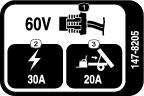
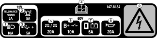
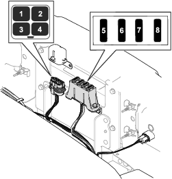
Locating the Fuses
Maintaining the Headlights
Replacing the Headlight
-
Disconnect the machine power; refer to Using the Battery-Disconnect Switch.
-
Open the hood.
-
Disconnect the electrical connector for the harness from the connector of the lamp assembly (Figure 47).
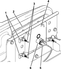
-
Remove the speed clips that secure the headlight to the headlight bracket (Figure 47).
Note: Retain all parts for installation of the new headlight.
-
Remove the headlight assembly by moving it forward through the opening in the front bumper (Figure 47).
-
Install the new headlight through the opening in the bumper (Figure 47).
Note: Ensure the adjustment posts are lined up with the holes in the mounting bracket behind the bumper.
-
Secure the headlight assembly with the speed clips that you removed in step 4.
-
Connect the electrical connector for the harness to the connector of the lamp assembly (Figure 47).
-
Adjust the headlights to direct the beams to the desired position, refer to Adjusting the Headlights.
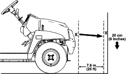
Adjusting the Headlights
Use the following procedure to adjust the headlight beam position whenever a headlight assembly is replaced or removed.
-
Park the machine on a level surface with the headlights approximately 7.6 m (25 ft) from a wall (Figure 48).
-
Measure the distance from the floor to the center of the headlight and make a mark on the wall at the same height.
-
Turn the key switch to the ON position, and turn on the headlights.
-
Take note of where the headlights aim on the wall.
The brightest part of the headlight beam should be 20 cm (8 inches) below the mark placed on the wall (Figure 48).
-
At the back of the headlight assembly, rotate adjustment screws (Figure 47) to pivot the headlight assembly and align the position of the cast beam.
-
Close the hood.
Drive System Maintenance
Maintaining the Tires
| Maintenance Service Interval | Maintenance Procedure |
|---|---|
| Every 100 hours |
|
-
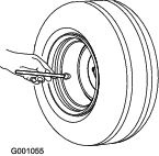
Inspect the tires and rims for signs of wear and damage.
Note: Operating accidents, such as hitting curbs, can damage a tire or rim and also disrupt wheel alignment, so inspect tire condition after an accident.
-
Torque the wheel lug nuts to 108 to 122 N∙m (80 to 90 ft-lb).
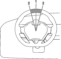
Inspecting the Steering and Suspension Components
| Maintenance Service Interval | Maintenance Procedure |
|---|---|
| Every 100 hours |
|
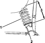
With the steering wheel at the centered position (Figure 49), turn the steering wheel to the left or right. If you turn the steering wheel more than 13 mm (1/2 inch) to the left or right, and the tires do not turn, check the following steering and suspension components to ensure that they are not loose or damaged:
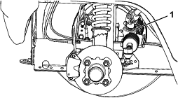
-
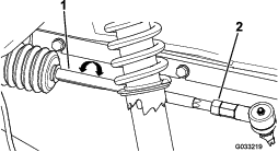
Steering shaft to the steering-rack assembly joint
Important: Inspect the condition and security of the pinion-shaft seal (Figure 50).
-
Steering-rack assembly tie rods
Adjusting the Wheel Alignment
| Maintenance Service Interval | Maintenance Procedure |
|---|---|
| Every 100 hours |
|
Preparing to Adjust Camber or Toe-in
-
Check the tire pressure to ensure that the front tires are inflated to 138 kPa (20 psi).
-
Either add weight to the driver's seat equal to the average operator who will run the machine, or have an operator sit on the seat. The weight or operator must remain on the seat for the duration of the adjustment procedure.
-
On a level surface, roll the machine straight back 2 to 3 m (6 to 10 ft) and then straight forward to the original starting position. This allows the suspension to settle into the operating position.
Adjusting the Camber
Owner provided tools: spanner wrench, Toro Part 132-5069; refer to your authorized Toro distributor.
Important: Make the camber adjustments only if you are using a front attachment or if there is uneven tire wear.
Note: This procedure can be performed on the front and rear tires.
-
Check the camber alignment at each wheel; the alignment should be as close to neutral (zero) as possible.
Note: The tires should be aligned with the tread evenly on the ground to reduce uneven wear.
-
If the wheel camber is out of alignment, use the spanner wrench to rotate the collar on the shock absorber to align the wheel (Figure 51).
Adjusting the Front Wheel Toe-in
Important: Before adjusting toe-in, ensure that the camber adjustment is as close to neutral as possible; refer to Adjusting the Camber.
-
Measure the distance between both of the front tires at the axle height at both the front and rear of the front tires (Figure 52).

-
If the measurement does not fall within 0 to +/- 3 mm (0 to +/- 1/8 inch), loosen the jam nuts at the outer end of the tie rods (Figure 53).
-
Rotate both tie rods to move the front of the tire inward or outward.
-
Tighten the tie rod jam nuts when the adjustment is correct.
-
Ensure that there is full travel of the steering wheel in both directions.
Checking the Transaxle-Fluid Level
| Maintenance Service Interval | Maintenance Procedure |
|---|---|
| Every 100 hours |
|
-
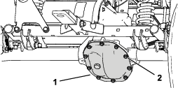
Remove the fill plug on the transaxle (Figure 54).
Note: The fluid level should be even with the bottom of the fill plug.
-
If the fluid level is low, remove the fill plug and add the specified fluid until it runs out of the hole (Figure 54).
-
Install the fill plug and torque it to 20 to 27 N∙m (15 to 20 ft-lb).
Changing the Transaxle Fluid
| Maintenance Service Interval | Maintenance Procedure |
|---|---|
| Every 100 hours |
|
| Every 800 hours |
|
Fluid Type: SAE 10W-30 (API service SJ or higher)
Fluid Capacity: 0.66 L (0.7 US qt)
-
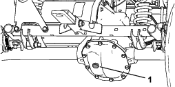
Align a drain pan under the transaxle cover (Figure 55).
-
Remove the bolts from the transaxle cover and drain the fluid completely (Figure 55).
Note: Retain the transaxle cover and bolt.
-
Install the transaxle cover using the previously removed bolts, and torque the bolts to 22 to 32 N∙m (16 to 24 ft-lb).
-
Remove the fill plug on the transaxle and fill the transaxle with the specified fluid until it runs out of the fill hole (Figure 54).
-
Install the fill plug and torque it to 20 to 27 N∙m (15 to 20 ft-lb).
Brake Maintenance
Checking the Parking Brake
-
Engage the parking brake by pulling the parking-brake lever toward you, until you feel tension.
-
If you do not feel tension when pulling the parking-brake toward you within 11.4 to 16.5 cm (4-1/2 to 6-1/2 inches) from the “P” symbol on the dash, then you need to adjust the parking brake; refer to Adjusting the Parking Brake.
Adjusting the Parking Brake
-
Ensure that the parking brake is disengaged.
-
Using jack stands, lift the rear of the machine; refer to Lifting the Machine.
-
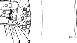
Using 2 wrenches, hold the adjusting post on the caliper in place with 1 wrench, and loosen the jam nut 1/4 turn with the other wrench (Figure 56).
-
While holding the adjusting post and the jam nut in place, turn the adjusting post in to tighten (Figure 56).
Note: Perform this step until you feel drag on the wheel.
-
While holding the adjusting post and the jam nut in place, back off 1/4 turn (Figure 56).
-
While holding the adjusting post and the jam nut in place, tighten the jam nut (Figure 56).
-
Perform steps 1 through 6 to the other side.
-
Verify that the parking brake is adjusted to the proper tension; refer to Checking the Parking Brake.
Note: If you cannot adjust the parking brake to the required tension, the brake pads may be worn and need to be replace. Contact your authorized Toro distributor for assistance.
Checking the Brake-Fluid Level
| Maintenance Service Interval | Maintenance Procedure |
|---|---|
| Before each use or daily |
|
Brake Fluid Type: DOT 3
-
Park the machine on a level surface, engage the parking brake, shut off the machine, and remove the key.
-
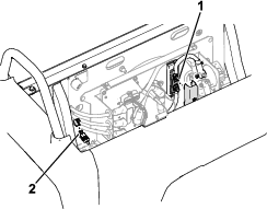
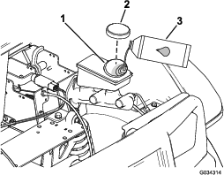
Raise the hood to gain access to the master-brake cylinder and reservoir (Figure 57).
-
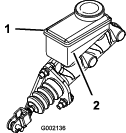
Look at the outline of the fluid level at the side of the reservoir (Figure 58).
Note: The level should be above the Minimum line.
-
If the fluid level is low, perform the following:
-
Close the hood of the machine.
Inspecting the Brakes
| Maintenance Service Interval | Maintenance Procedure |
|---|---|
| Every 100 hours |
|
Important: Brakes are a critical safety component of the machine. Closely inspect them at the recommended service interval to ensure optimum performance and safety.
-
Inspect the brake lining for wear or damage. If the lining (brake pad) thickness is less than 1.6 mm (1/16 inch), replace the brake lining.
-
Inspect the backing plate and other components for signs of excessive wear or deformation. Replace any deformed components.
-
Check the brake-fluid level; refer to Checking the Brake-Fluid Level.
Replacing the Service and Parking-Brake Pads
| Maintenance Service Interval | Maintenance Procedure |
|---|---|
| Every 400 hours |
|
Contact your authorized Toro distributor to inspect and possibly replace the service and parking-brake pads.
Changing the Brake Fluid
| Maintenance Service Interval | Maintenance Procedure |
|---|---|
| Every 1,000 hours |
|
Contact your authorized Toro distributor.
Chassis Maintenance
Adjusting the Cargo-Bed Latches
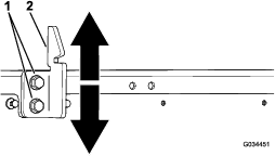
If the cargo-bed latch is out of adjustment, the cargo bed vibrates up and down as you drive the machine. You can adjust the latch posts to make the latches hold the cargo bed snugly to the chassis.
-
Verify that the cargo bed is latching.
Note: If the cargo bed does not latch, the bed-latch striker is likely too low. If the cargo bed latches, but vibrates up and down as you drive, the bed-latch striker is likely too high.
-
Raise the cargo bed; Raising the Cargo Bed to the Dump Position.
-
Loosen the 2 bolts on the bed-latch striker and move the striker up or down, depending on if the striker is too high or too low (Figure 59).
-
Tighten the 2 bolts on the bed-latch striker (Figure 59).
-
Verify that the adjustment is correct by latching the cargo bed several times.
Cleaning
Washing the Machine
| Maintenance Service Interval | Maintenance Procedure |
|---|---|
| Before each use or daily |
|
Wash the machine as needed using water alone or with a mild detergent. You may use a rag when washing the machine.
Important: Do not use brackish or reclaimed water to clean the machine.
Important: Pressurized water is not recommended when washing the machine. It may damage the electrical system, loosen important decals, or wash away necessary grease at friction points. Avoid excessive use of water, especially near the control panel, motor, motor controller, charger, back of the dashboard, and batteries.
Storage
Storage Safety
-
Shut off the machine, remove the key, and wait for all movement to stop before you leave the operator’s position. Allow the machine to cool before adjusting, servicing, cleaning, or storing it.
-
Do not store the machine or fuel container where there is an open flame, spark, or pilot light, such as on a water heater or other appliance.
Storing the Machine
-
Park the machine on a level surface, engage the parking brake, shut off the machine, and remove the key.
-
Clean dirt and grime from the entire machine, including the outside of the motor housing.
Important: You can wash the machine with mild detergent and water. Do not use high-pressure water to wash the machine. Pressure-washing may damage the electrical system or wash away necessary grease at friction points. Avoid excessive use of water, especially near the control panel, lights, motor, and battery.
-
Inspect the brakes; refer to Inspecting the Brakes.
-
Check the tire pressure; refer to Checking the Tire Pressure.
-
Check and tighten all bolts, nuts, and screws. Repair or replace any part that is damaged.
-
Paint all scratched or bare metal surfaces.
Note: Paint is available from your authorized Toro distributor.
-
Cover the machine to protect it and keep it clean.
Battery Storage Requirements
Note: You do not need to remove the batteries from the machine for storage.
Refer to the temperature limits for storage in the following table:
| Storage Temperature | Appropriate Storage Time |
| 45° to 55°C (113° to 131°F) | 1 week |
| 25° to 45°C (77° to 113°F) | 3 weeks |
| -20° to 25°C (-4° to 77°F) | 52 weeks |
Important: Temperatures outside of these ranges will damage your batteries.The temperature that the batteries are stored at will affect their long-term life. Storage for long periods of time at extreme temperatures will reduce the battery life. For temperatures above 25°C (77°F), only store the machine for the appropriate amount of time indicated in the table.
-
Before you store the machine, charge or discharge the batteries between 40% to 60%.
Note: A 50% charge is optimal to ensure a maximum battery life. When the batteries are charged to 100% before storage, the battery life shortens.If you anticipate that the machine will be stored for a longer period of time, charge the batteries to around 60%.
-
For every 6 months of storage, check the battery-charge level and ensure that it is between 40% to 60%. If the charge is below 40%, charge the batteries between 40% to 60%.
-
After charging the batteries, disconnect the battery charger from power.