Disclaimers and Regulatory Information
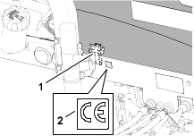
This product complies with all relevant European directives; for details, please see the separate product specific Declaration
of Conformity (DOC) sheet.
It is a violation of California Public Resource Code Section 4442 or 4443 to use or operate the engine on any forest-covered,
brush-covered, or grass-covered land unless the engine is equipped with a spark arrester, as defined in Section 4442, maintained
in effective working order, or the engine is constructed, equipped, and maintained for the prevention of fire.
The enclosed engine owner's manual is supplied for information regarding the US Environmental Protection Agency (EPA) and
the California Emission Control Regulation of emission systems, maintenance, and warranty. Replacements may be ordered through
the engine manufacturer.
 |
| |
| CALIFORNIA |
| |
| Proposition 65 |
| |
| Diesel engine exhaust and some of its constituents are known to the
State of California to cause cancer, birth defects, and other reproductive
harm. |
| |
| Battery posts, terminals, and related accessories contain lead and
lead compounds, chemicals known to the State of California to cause
cancer and reproductive harm. Wash hands after handling. |
| |
| Use of this product may cause exposure to chemicals known to the
State of California to cause cancer, birth defects, or other reproductive
harm. |
| |
Intended Use
This machine is a ride-on, reel-blade lawn mower intended to be used by professional, hired operators in commercial applications.
It is primarily designed for cutting grass on well-maintained turf. Using this product for purposes other than its intended
use could prove dangerous to you and bystanders.
Read this information carefully to learn how to operate and maintain your product properly and to avoid injury and product
damage. You are responsible for operating the product properly and safely.
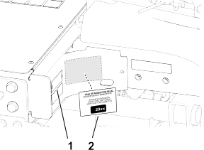
Getting Help
Visit www.Toro.com for product safety and operation training materials, accessory information, help finding a dealer, or to register your product.
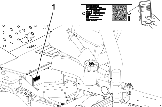
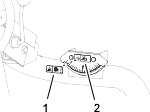
Whenever you need service, genuine Toro parts, or additional information, contact an Authorized Service Dealer or Toro Customer Service and have the model and serial numbers of your product ready. These numbers are located on the serial plate
on your product  . Write the numbers in the space provided.
With your mobile device, you can scan the QR code on the serial number decal (if equipped) to access warranty, parts, and
other product information.
|
Model Number:
|
|
Serial Number:
|
|
Manual Conventions
This manual identifies potential hazards and has safety messages identified by the safety-alert symbol, which signals a hazard
that may cause serious injury or death if you do not follow the recommended precautions.
This manual uses 2 words to highlight information. Important calls attention to special mechanical information and Note emphasizes general information worthy of special attention.
Safety Alert Classifications
The safety-alert symbol shown in this manual and on the machine identifies important safety messages that you must follow
to prevent accidents.
Safety-alert symbol appears above information that alerts you to unsafe actions or situations and is followed by the word
DANGER, WARNING, or CAUTION.
 |
Danger |
|
Danger indicates an imminently hazardous situation which, if not avoided, will result in death or serious injury.
|
Warning |
|
Warning indicates a potentially hazardous situation which, if not avoided, could result in death or serious injury.
|
Caution |
|
Caution indicates a potentially hazardous situation which, if not avoided, may result in minor or moderate injury.
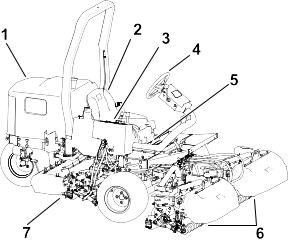
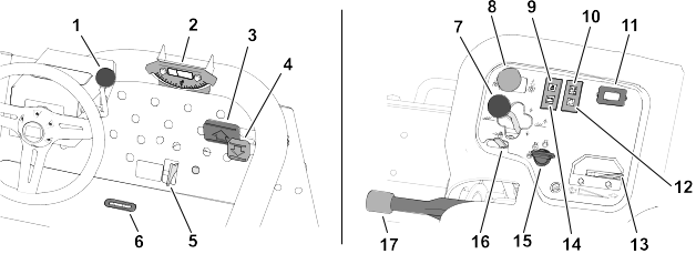
G403727
- Engine hood
- Operator's seat
- Control arm
- Steering wheel
- Seat-adjustment lever
- Front cutting units
- Rear cutting unit
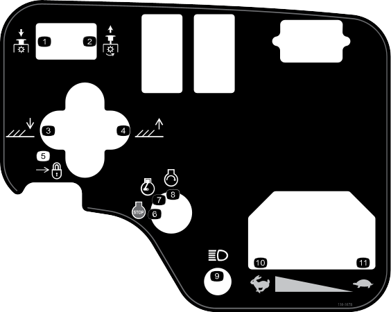
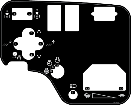
Controls
G450123
-
Tilt-steering lever
-
Slope indicator
-
Forward traction pedal
-
Reverse traction pedal
-
Mow/transport slide
-
Indicator slot
-
Cutting-unit shift lever
-
Cutting-unit drive switch
-
Oil-pressure light
-
Engine coolant temperature light
-
Hour meter
-
Glow-plug indicator light
-
Throttle
-
Alternator light
-
Key switch
-
Lift lever lock
-
Parking brake
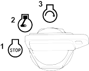
Key Switch
G444247
- Off
- Run/preheat the engine
Note: When the key is in the Run/Preheat position, the glow plug energizes and the indicator light illuminates for approximately 7 seconds.
- Start
Traction Pedals
G450112
- Move forward—press the forward traction pedal.
- Move backward (or to assist in stopping when moving forward)—press the reverse traction pedal.
Allow the pedals to move or move them to the Neutral position to stop the machine.
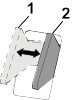
Mow/Transport Slide
G444501
- Transport—move the slide to this position when transporting the machine.
Note: The cutting units do not lower when the slide is in the Transport position.
- Mow—move the slide to this position to operate the cutting units.
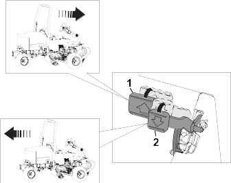
Cutting Unit Shift Lever
Raise/Lower
G465011
- Lower
Note: The cutting units do not lower unless the engine is running. You do not need to hold the lever in the forward position while
the cutting units are lowered.
- Raise
Note: The reels do not run while the cutting units are raised.
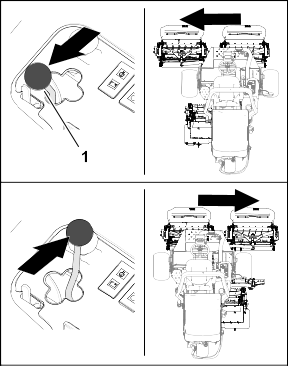
Side Shift
Model 03171
G465022
- Shift right
- Shift left
Note: Sideshift the cutting units only when they are raised or if they are on the ground and the machine is moving.
|
Danger |
|
Shifting the cutting units downhill decreases machine stability. This could cause a rollover, which may result in personal
injury or death.
Shift the cutting units uphill while on a side hill.
Slope Indicator
The slope indicator indicates the side hill angle of the machine in degrees.
Indicator Slot
The slot in the operator platform indicates when the cutting units are in the center position.
Cutting-Unit Drive Switch
Throttle
G465025
- Increase engine speed
- Decrease engine speed
Lift Lever Lock
G465028
- Unlock
- Lock (prevents cutting units from dropping)
Parking Brake
Whenever the engine is shut off, engage the parking brake to prevent accidental movement of the machine.
G465039
- Engaged
- Disengaged
Note: The engine shuts off if you press the traction pedal with the parking brake engaged.
Oil Pressure Warning Light
The oil pressure warning light glows if the engine oil pressure drops below a safe level.
Engine Coolant Temperature Warning Light
The temperature warning light illuminates if the engine coolant temperature is high. At this temperature, the cutting units
shut off. If the coolant temperature rises another 5.5°C (10°F), the engine shuts off to prevent further damage.
Alternator Light
The alternator light shuts off when the engine runs. If the alternator light illuminates while the engine runs, check the
charging system and repair it as necessary.
Glow-Plug Indicator Light
The glow-plug indicator light illuminates when the glow plugs are energized.
Hour Meter
The hour meter indicates the total hours of machine operation. The hour meter starts to function whenever the key switch is
on.
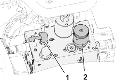
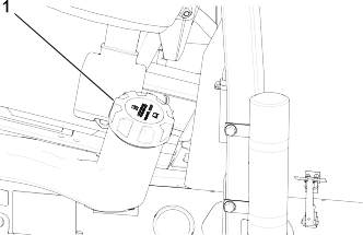
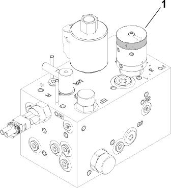
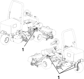
Mower Manifold
The mower manifold is located under the control-console cover.
G465040
-
Backlap control
-
Reel speed control
Reel Speed Knob
Use the reel speed knob of the mower manifold to adjust the clip rate (reel speed) of the cutting units.
Turn the reel speed knob counterclockwise to increase the reel speed; turn the knob clockwise to slow the reel speed.
Backlap Control
The backlap lever controls the direction the cutting units rotate when you are mowing or when you backlap the reels and bedknives.
Rotate the backlap lever to the F position when mowing; rotate the lever to the R position when backlapping the cutting units.
Note: Do not change the backlap lever position while the reels are rotating.
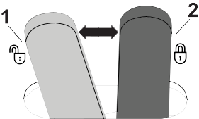
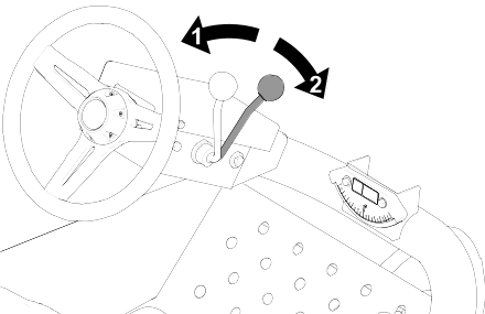
Tilt-Steering Lever
Unlock the tilt-steering lever, tilt the steering wheel to the desired position, and lock the lever to secure the position.
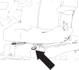
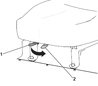
Seat Adjustment Lever
Move the lever to the unlock position, adjust the seat to the desired position, and lock the lever to secure the seat position.
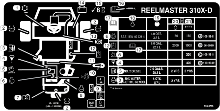
Specifications
Note: Specifications and design are subject to change without notice.
|
Transport width
|
203 cm (80 inches) in 183 cm (72 inches) width of cut;
234 cm (92 inches) in 216 cm (85 inches) width of cut
|
|
Width of cut
|
183 cm (72 inches) or 216 cm (85 inches)
|
|
Length
|
248 cm (93 inches)
|
|
Height
|
193 cm (76 inches) with ROPS
|
|
Net weight*
|
844 kg (1,860 lb)
|
|
Fuel tank capacity
|
28 L (7.5 US gallons)
|
|
Transport speed
|
0 to 14 km/h (0 to 9 mph)
|
|
Mowing speed
|
0 to 10 km/h (0 to 6 mph)
|
|
Reverse speed
|
0 to 6 km/h (0 to 4 mph)
|
|
*With cutting units and fluids
|
Attachments/Accessories
A selection of Toro approved attachments and accessories is available for use with the machine to enhance and expand its capabilities. Contact
your Authorized Service Dealer or authorized Toro distributor or go to www.Toro.com for a list of all approved attachments and accessories.
To ensure optimum performance and continued safety certification of the machine, use only genuine Toro replacement parts and accessories.
Note: Determine the left and right sides of the machine from the normal operating position.
Note: Download a free copy of the electrical or hydraulic schematic by visiting www.Toro.com and searching for your machine from the Manuals link on the home page.
Refer to your engine owner’s manual and cutting unit Operator's Manual for additional maintenance procedures.
Recommended Maintenance Schedule
|
After the first hour
|
|
- |
- |
- |
|
After the first 10 hours
|
|
- |
- |
- |
|
|
130-1241 |
1 |
Alternator/fan belt |
|
95-8730
|
1 |
Hydrostat drive belt |
|
After the first 50 hours
|
|
127-0511 |
1 |
Engine-oil filter |
|
121-6395
|
1 |
15W-40 Premium Engine Oil (5 gallons) |
|
121-6394
|
1 |
15W-40 Premium Engine Oil (55 gallons) |
|
Before each use or daily
|
|
- |
- |
- |
|
|
- |
- |
- |
|
|
121-6395
|
1 |
15W-40 Premium Engine Oil (5 gallons) |
|
121-6394
|
1 |
15W-40 Premium Engine Oil (55 gallons) |
|
|
- |
- |
- |
|
|
- |
- |
- |
|
|
- |
- |
- |
|
|
- |
- |
- |
|
|
- |
- |
- |
|
|
133-8086 |
1 |
PX Extended Life Hydraulic Fluid (5 gallons) |
|
133-8087 |
1 |
PX Extended Life Hydraulic Fluid (55 gallons) |
|
|
- |
- |
- |
|
Every 25 hours
|
|
- |
- |
- |
|
Every 50 hours
|
|
108-1190 |
1 |
Premium all-purpose grease (14 oz) |
|
Every 100 hours
|
|
130-1241
|
1 |
Alternator/fan belt |
|
95-8730
|
1 |
Hydrostat drive belt |
|
Every 150 hours
|
|
127-0511 |
1 |
Engine-oil filter |
|
121-6395
|
1 |
15W-40 Premium Engine Oil (5 gallons) |
|
121-6394
|
1 |
15W-40 Premium Engine Oil (55 gallons) |
|
Every 200 hours
|
|
108-3811
|
1 |
Air-cleaner filter |
|
|
- |
- |
- |
|
|
- |
- |
- |
|
Every 400 hours
|
|
- |
- |
- |
|
|
110-9049 |
1 |
Fuel filter canister |
|
Every 500 hours
|
|
108-1190 |
1 |
Premium all-purpose grease (14 oz) |
|
Every 800 hours
|
Change the hydraulic fluid (if you are not using the recommended hydraulic fluid or have ever filled the reservoir with an alternative fluid).
|
133-8086 |
1 |
PX Extended Life Hydraulic Fluid (5 gallons) |
|
133-8087 |
1 |
PX Extended Life Hydraulic Fluid (55 gallons) |
Replace the hydraulic filter (if you are not using the recommended hydraulic fluid or have ever filled the reservoir with an alternative fluid).
|
86-3010 |
1 |
Hydraulic filter |
|
Every 1,000 hours
|
|
86-3010 |
1 |
Hydraulic filter |
|
Every 2,000 hours
|
|
133-8086 |
1 |
PX Extended Life Hydraulic Fluid (5 gallons) |
|
133-8087 |
1 |
PX Extended Life Hydraulic Fluid (55 gallons) |
|
Every 2 years
|
|
- |
- |
- |
|
Flush and replace the cooling system fluid (take the machine to an Authorized Service Dealer or Distributor or refer to the
Service Manual).
|
- |
- |
- |
Daily Maintenance Checklist
|
Check the safety interlock operation.
|
|
|
|
|
|
|
|
|
Check the brake operation.
|
|
|
|
|
|
|
|
|
Check the levels of the engine oil and fuel.
|
|
|
|
|
|
|
|
|
Check the cooling-system fluid level.
|
|
|
|
|
|
|
|
|
Drain the water/fuel separator.
|
|
|
|
|
|
|
|
|
Check the air-filter, dust cup, and burp valve.
|
|
|
|
|
|
|
|
|
Check the radiator and screen for debris.
|
|
|
|
|
|
|
|
|
Check for unusual engine noises.1
|
|
|
|
|
|
|
|
|
Check for unusal operating noises.
|
|
|
|
|
|
|
|
|
Check the fluid level of the hydraulic system.
|
|
|
|
|
|
|
|
|
Check the hydraulic hoses for damage.
|
|
|
|
|
|
|
|
|
Check for fluid leaks.
|
|
|
|
|
|
|
|
|
Check the fuel level.
|
|
|
|
|
|
|
|
|
Check the tire pressure.
|
|
|
|
|
|
|
|
|
Check the instrument operation.
|
|
|
|
|
|
|
|
|
Check the reel-to-bedknife contact adjustment.
|
|
|
|
|
|
|
|
|
Check the height-of-cut adjustment.
|
|
|
|
|
|
|
|
|
Lubricate all grease fittings.2
|
|
|
|
|
|
|
|
|
Touch-up damaged paint.
|
|
|
|
|
|
|
|
|
Wash the machine.
|
|
|
|
|
|
|
|
-
Check the glow plug and injector nozzles if the engine starts hard, produces excess smoke, or runs rough.
-
Immediately after every washing, regardless of the interval listed
|
Notation for Areas of Concern
Pre-Maintenance Procedures
Preparing for Maintenance
-
Park the machine on a level surface, lower the cutting units, and engage the parking brake.
-
Shut off the engine, remove the key, wait for all moving parts to stop, and allow the engine to cool.
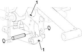
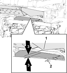
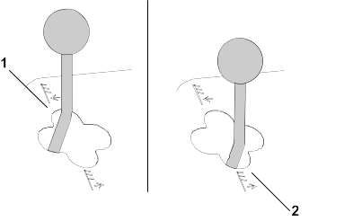
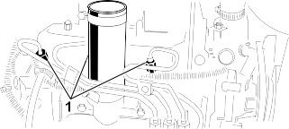
Lifting the Front of the Machine
-
Chock the tires.
-
Jack the front of the machine under the square tube  of the lower frame as closely to the side plate as possible.
-
Support the machine with jack stands rated for the weight of the machine under the square tube or wheel motors.
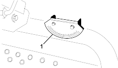
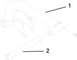
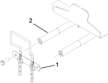
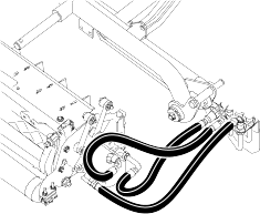
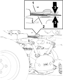
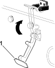
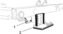
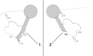
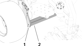
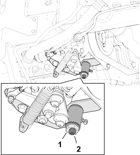
Lifting the Back of the Machine (Using a Hoist)
-
Chock the tires.
-
Secure the hoist to the tie-down loop  of the rear-wheel fork .
-
Carefully raise the machine.
-
Support the machine with jack stands rated for the weight of the machine under the frame .
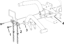
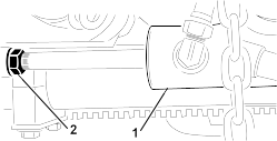
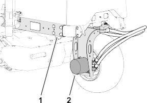
Lifting the Back of the Machine (Using a Jack)
-
Chock the tires.
-
Jack the back of the machine under the rear wheel motor .
-
Support the machine with jack stands rated for the weight of the machine under the frame .
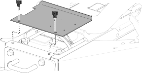
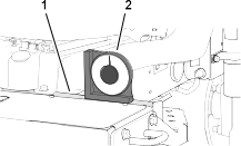
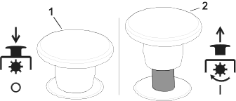
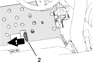
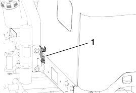
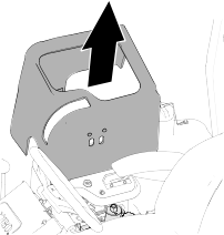
Removing the Battery Cover
-
Remove the battery cover as shown.
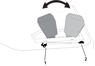
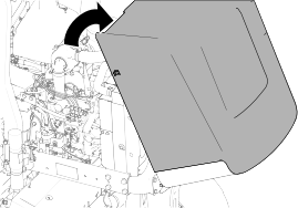
Opening the Hood
-
Release the latches on both sides of the hood.
-
Rotate the hood open.
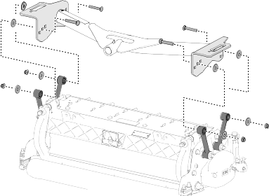
Lubrication
Greasing the Bearings and Bushings
The machine has grease fittings that must be lubricated regularly. Dusty and dirty operating conditions could cause dirt to
get into the bearings and bushings, resulting in accelerated wear. Lubricate the grease fittings immediately after every washing,
regardless of the interval specified.
-
Prepare the machine for maintenance.
-
Grease all machine fittings with No. 2 lithium grease.
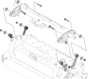
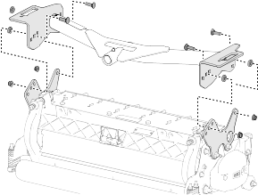
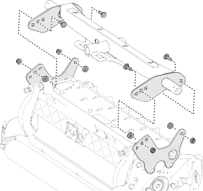
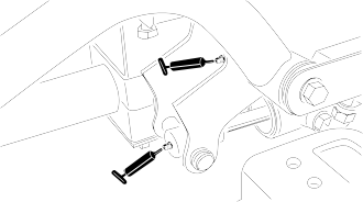
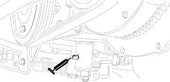
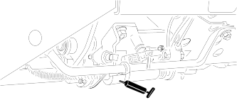
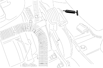
Grease Fitting Locations
Grease Specification: No. 2 lithium grease
|
Rear cutting unit pivot
|
|
|
Front cutting unit pivot
|
|
|
Sidewinder cylinder ends (2 fittings; Model 03171 only)
|
|
|
Steering pivot
|
|
|
Rear lift arm pivot and lift cylinder (2 fittings)
|
|
|
Left front lift arm pivot and lift cylinder (2 fittings)
|
|
|
Right front lift arm pivot and lift cylinder (2 fittings)
|
|
|
Neutral adjust mechanism
|
|
|
Mow/transport slide
|
|
|
Belt tension pivot
|
|
|
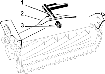
Steering cylinder
|
|
Note: If desired, install an additional grease fitting in the other end of the steering cylinder. Remove the tire, install the fitting,
grease the fitting, remove the fitting, and install the plug.
|
|
Checking the Sealed Bearings
Bearings rarely fail from defects in materials or workmanship. The most common reason for failure is moisture and contamination
working its way past the protective seals. Bearings that are greased rely upon regular maintenance to purge harmful debris
from the bearing area. Sealed bearings rely on an initial fill of special grease and a robust integral seal to keep contaminants and moisture out of the
rolling elements.
The sealed bearings require no lubrication or short-term maintenance. This minimizes routine service required and reduces
the potential of turf damage due to grease contamination. These sealed bearing packages will provide good performance and
life under normal use, but you should periodically inspect the bearing condition and seal integrity to avoid downtime. Inspect
the bearings seasonally and replace the them if they are damaged or worn. Bearings should operate smoothly with no detrimental
characteristics such as high heat, noise, looseness, or indications of corrosion (rust).
Due to the operating conditions these bearing/seal packages are subject to (i.e., sand, turf chemicals, water, impacts, etc.)
they are considered normal wear items. Bearings that fail due to causes other than defects in materials or workmanship are
typically not covered under the warranty.
Note: Bearing life can be negatively affected by improper wash-down procedures. Do not wash down the machine when it is still hot
and avoid directing high-pressure or high-volume spray at the bearings.
Engine Maintenance
Engine Oil Specifications
Oil Type
Use high-quality, low-ash engine oil that meets or exceeds API service category CH-4 or higher.
Use the following engine oil viscosity grade:
- Preferred oil: SAE 15W-40 [-17°C (above 0°F)]
- Alternate oil: SAE 10W-30 or 5W-30 (all temperatures)
Toro Premium Engine Oil is available from your authorized Toro distributor in either 15W-40 or 10W-30 viscosity grades.
Crankcase Capacity
Approximately 3.8 L (4.0 US qt) with the filter
Checking the Engine-Oil Level
Note: Check the oil when the engine is cool. If the engine is warm, wait 10 minutes before checking.
If the oil level is below the lower limit mark on the dipstick, add oil gradually until the level reaches the upper limit
mark on the dipstick.
Keep the engine-oil level between the upper and lower limits on the dipstick. Overfilling or underfilling the engine oil may
cause severe engine damage.
-
Prepare the machine for maintenance.
-
Open the hood.
-
Check the level of the engine oil.
-
Close and latch the hood.
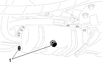
Changing the Engine Oil and Filter
-
Prepare the machine for maintenance.
-
Unlatch and open the hood.
-
Perform the following steps to change the engine oil:
-
Remove either drain plug and allow all of the existing oil to drain out of the engine.
-
Install the drain plug.
-
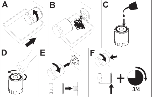
Change the engine-oil filter.
Note: Do not overtighten the filter.
-
Add oil to the crankcase.
-
Close and latch the hood.
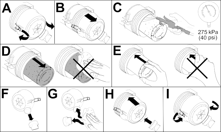
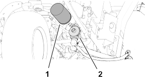
Servicing the Air Cleaner
- Check the whole intake system for leaks, damage, or loose hose clamps. Do not use a damaged air filter.
- Service the air-cleaner filter at the recommended service interval or earlier if engine performance declines due to extremely
dusty, dirty conditions. Changing the air filter before it is necessary only increases the chance of dirt entering the engine
when the filter is removed.
Ensure that the cover is seated correctly, seals with the air-cleaner body, and the rubber outlet valve is in a downward position—between the 5 o’clock and 7 o’clock positions when viewed from the end.
Fuel System Maintenance
This Operator’s Manual contains more detailed fuel and fuel system maintenance information than the engine Owner’s Manual, which is a general-purpose reference relating to fuel and fuel maintenance.
Ensure that you understand that the fuel system maintenance, fuel storage, and fuel quality require your attention to avoid
downtime and extensive engine repairs.
The fuel system has extremely tight tolerances due to the emissions and control requirements. Diesel fuel quality and cleanliness
is more important for the longevity of today’s high-pressure common rail (HPCR) fuel-injection system used on diesel engines.
Water or air in the fuel system will damage your engine! Do not assume that new fuel is clean. Ensure that your fuel is from
a quality supplier, store your fuel correctly, and use your fuel supply within 180 days.
If you do not follow the procedures for fuel filter replacement, fuel system maintenance, and fuel storage, the engine fuel
system could fail prematurely. Perform all fuel system maintenance at the specified intervals or whenever the fuel is contaminated
or its quality is poor.
Fuel Storage
Appropriate fuel storage is critical for your engine. Proper maintenance of fuel storage tanks is often overlooked and leads
to the contamination of fuel delivered to the machine.
- Acquire only enough fuel that you will consume within 180 days. Do not use fuel that has been stored for more than 180 days.
This helps eliminate water and other contaminates in the fuel.
- If you do not remove the water from the storage tank or machine fuel tank, it can lead to rust or contamination in the storage
tank and fuel system components. Tank sludge developed by mold, bacteria, or fungus restricts flow and clogs the filter and
fuel injectors.
- Inspect your fuel storage tank and machine fuel tank regularly to monitor the fuel quality in the tank.
- Ensure that your fuel comes from a quality supplier.
- If you find water or contaminants in your storage tank or machine fuel tank, work with your fuel provider to correct the problem
and perform all fuel system maintenance.
- Do not store diesel fuel in tanks or canisters made with zinc-plated components.
Servicing the Fuel Tank
-
Prepare the machine for maintenance.
-
Drain and clean the tank if the fuel system becomes contaminated or if the machine will be stored for an extended period.
Use clean fuel to flush out the tank.
Inspecting the Fuel Lines and Connections
-
Prepare the machine for maintenance.
-
Unlatch and open the hood.
-
Inspect the fuel lines and fittings for deterioration, damage, or loose connections.
Note: Repair or replace any damaged or worn the fuel lines or fittings.
-
Close and latch the hood.
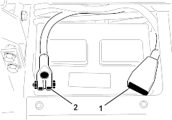
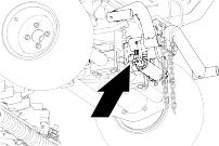
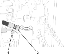
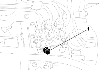
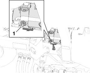
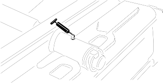
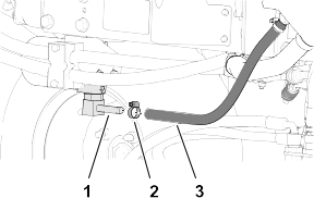
Servicing the Fuel/Water Separator
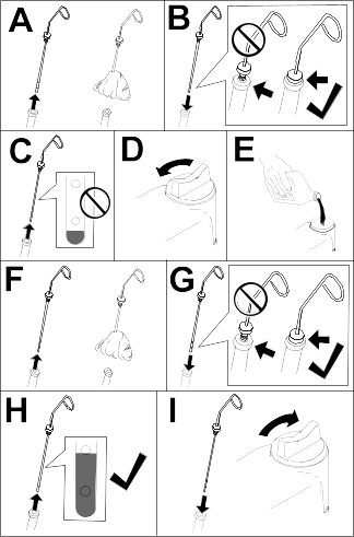
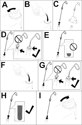
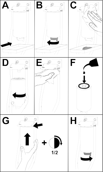
Draining the Fuel/Water Separator
-
Prepare the machine for maintenance.
-
Drain the water separator as shown.
-
Start the engine, check for leaks, and shut off the engine.
Note: Repair all fuel leaks.
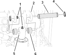
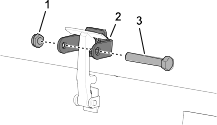
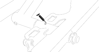
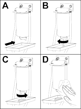
Replacing the Fuel/Water Separator Filter
-
Replace the filter as shown.
-
Start the engine, check for leaks, and shut off the engine.
Note: Repair all fuel leaks.
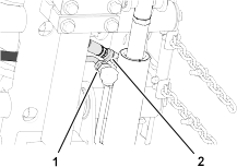
Bleeding Air from the Injectors
Note: Use this procedure only if the fuel system has been purged of air through normal priming procedures and the engine does not
start.
-
Prepare the machine for maintenance.
-
Unlatch and open the hood, and allow the engine to cool.
-
Loosen the tube nut for the fuel line to the No. 1 fuel-injector nozzle.
-
Move the throttle to the Fast position.
-
Turn the key to the Start position and watch the fuel flow around the connector. Turn the key to the Off position when there is a continuous flow.
To prevent overheating of the starter motor, do not engage the starter for longer than 15 seconds. After 10 seconds of continuous
cranking, wait 60 seconds before engaging the starter motor again.
-
Tighten the tube nut securely.
-
Clean any fuel from the engine.
-
Repeat steps 3 through 7 for the remaining fuel-injector nozzles.
-
Start the engine, check for leaks, and shut off the engine.
Note: Repair all fuel leaks.
-
Close and latch the hood.
Electrical System Maintenance
Servicing the Battery
-
Prepare the machine for maintenance.
-
Remove the battery cover.
-
Remove the filler caps of the battery.
-
Maintain the battery electrolyte level in the battery cells with distilled or demineralized water.
Note: Do not fill the cells above the bottom of the split ring inside each cell.
-
Install the filler caps with the vents pointing to the rear (toward the fuel tank).
-
Clean the top of the battery by washing it periodically with a brush dipped in ammonia or bicarbonate of soda solution. Flush
the top surface with water after cleaning.
Do not remove the filler caps while cleaning.
-
Check the battery cable clamps and battery posts for corrosion. If corrosion occurs, perform the following:
-
Disconnect the negative (–) battery cable.
-
Disconnect the positive (+) battery cable.
-
Clean the clamps and posts separately.
-
Connect the positive (+) battery cable.
-
Connect the negative (–) battery cable.
-
Coat the clamps and terminals with battery terminal protector.
-
Check that the battery cable clamps are tight on the battery posts.
-
Install the battery cover.
Note: Store the machine where the temperature is cooler rather than warmer to prevent the battery from discharging more rapidly.
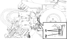
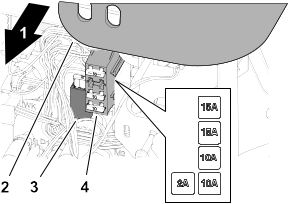
Servicing the Fuses
-
Prepare the machine for maintenance.
-
Lift the cover from the control arm.
G416222
-
Right side of the machine
-
Control-arm cover
-
Fuse holder
-
Fuse block
-
Locate the open fuse in the fuse holder or fuse block.
-
Replace the fuse with the same type and amperage fuse.
-
Assemble the cover onto the control arm.
Drive System Maintenance
Checking the Tire Pressure
|
Warning |
|
Low tire pressure decreases machine side hill stability. This could cause a rollover, which could result in death or serious
injury.
Do not under-inflate the tires.
Note: Maintain the recommended pressure in all tires to ensure a good quality of cut and proper machine performance.
-
Measure the air pressure in each tire. The correct air pressure in the tires is 97 to 110 kPa (14 to 16 psi).
-
If needed, add air to of remove air from the tires until you measure 97 to 110 kPa (14 to 16 psi).
Torquing the Wheel Nuts
-
Torque the wheel nuts in a crossing pattern to 61 to 88 N∙m (45 to 65 ft-lb).
|
Warning |
|
Failing to maintain proper torque of the wheel nuts could result in death or serious injury.
Maintain proper torque of the wheel nuts.
Adjusting the Traction Drive for Neutral
If the machine moves when the traction pedal is in the neutral position, adjust the traction cam.
-
Prepare the machine for maintenance.
-
Raise a front wheel and a rear wheel off the ground and place support blocks under the frame.
|
Warning |
|
If the machine is not supported adequately, it may accidentally fall, which could result in death or serious injury.
Raise a front wheel and the rear wheel off the ground to prevent the machine from moving during the adjustment.
-
Loosen the locknut on the traction adjustment cam .
|
Warning |
|
The engine must be running to make a final adjustment of the traction adjustment cam. Contact with hot or moving parts could
result in death or serious injury.
Keep your hands, feet, face, and other body parts away from the muffler, other hot parts of the engine, and rotating parts.
-
Start the engine and rotate the cam hex in both directions to determine the mid position of the neutral span.
-
Tighten the locknut securing the adjustment.
-
Shut off the engine.
-
Remove the support blocks and lower the machine to the ground. Test drive the machine to ensure that it does not move when
the traction pedal is in neutral.
Cooling System Maintenance
Coolant Specifications
The coolant reservoir is filled at the factory with a 50/50 solution of water and ethylene glycol base extended-life coolant.
Use only commercially available coolants that meet the specifications listed in the Extended Life Coolant Standards Table.
Do not use conventional (green) inorganic-acid technology (IAT) coolant in your machine. Do not mix conventional coolant with
extended-life coolant.
Coolant Type Table
|
Extended-life antifreeze
|
Organic-acid technology (OAT)
|
Do not rely on the color of the coolant to identify the difference between conventional (green) inorganic-acid technology
(IAT) coolant and extended-life coolant.
Coolant manufacturers may dye extended-life coolant in one of the following colors: red, pink, orange, yellow, blue, teal,
violet, and green. Use coolant that meets the specifications in the Extended Life Coolant Standards Table.
|
Extended Life Coolant Standards
|
D3306 and D4985
|
J1034, J814, and 1941
|
Coolant concentration should be a 50/50 mixture of coolant to water.
- Preferred: When mixing coolant from a concentrate, mix it with distilled water.
- Preferred option: If distilled water is not available, use a pre-mix coolant instead of a concentrate.
- Minimum requirement: If distilled water and pre-mix coolant are not available, mix concentrated coolant with clean drinkable water.
Cooling system capacity
Approximately 5.7 L (6 US qt)
Checking the Coolant Level
|
Caution |
|
If the engine has been running, the pressurized, hot coolant can escape, which could result in minor or moderate injury.
- Do not open the radiator cap when the engine is running.
- Use a rag when opening the radiator cap, and open the cap slowly to allow steam to escape.
-
Prepare the machine for maintenance.
-
Unlatch and open the hood.
-
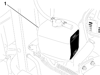
Check the coolant level in the expansion tank .
Note: With a cold engine, the coolant level should be approximately midway between the marks on the side of the tank.
-
If the coolant level is low remove the expansion tank cap, add the specified coolant to the tank until the coolant level is
midway between the marks on the side of the tank, and assemble the cap to the tank.
Do not overfill the expansion tank.
-
Close and latch the hood.
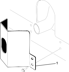
Cleaning the Engine Cooling System
-
Prepare the machine for maintenance.
-
Unlatch and open the hood.
-
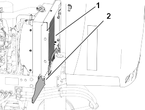
Clean the engine area thoroughly of all debris.
-
Remove the lower radiator shield .
-
Clean both sides of the radiator area thoroughly with water or compressed air.
-
Install the lower radiator shield.
-
Close and latch the hood.
Brake Maintenance
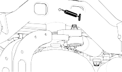
Adjusting the Parking Brake
-
Prepare the machine for maintenance.
-
Loosen the setscrew securing the knob to the parking-brake lever .
-
Rotate the knob until a force of 133 to 178 N (30 to 40 lb) is required to actuate the lever.
-
Tighten the setscrew.
Belt Maintenance
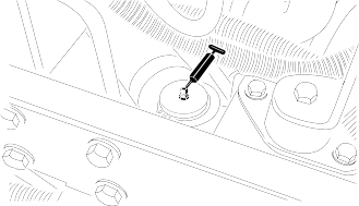
Servicing the Engine Belts
Tensioning the Alternator/Fan Belt
-
Prepare the machine for maintenance.
-
Unlatch and open the hood.
-
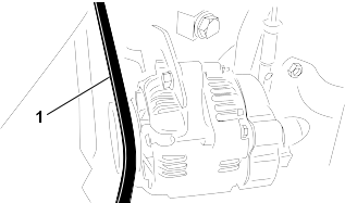
Check the alternator/fan belt tension by pressing the belt midway between the alternator and crankshaft pulleys.
Note: With 98 N (22 lb) of force, the belt should deflect 11 mm (7/16 inch).
-
If the deflection is incorrect, complete the following procedure to tension the belt:
-
Loosen the bolt securing the brace to the engine and the bolt securing the alternator to the brace.
-
Insert a pry bar between the alternator and engine and pry the alternator outward.
-
When you achieve proper belt tension, tighten the alternator and brace bolts to secure the adjustment.
-
Close and latch the hood.
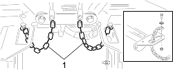
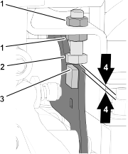
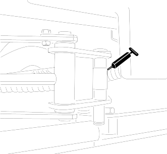
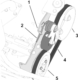
Replacing the Hydrostat Drive Belt
-
Insert a nut driver or small piece of tubing onto the end of the belt tensioning spring.
|
Warning |
|
When you replace the hydrostat drive belt, you must release the tension on the spring, which is under a heavy load. Releasing
the tension on the spring improperly could result in death or serious injury.
Be careful when releasing the tension on the spring.
-
Push down the end of the belt-tension spring down and out of the notch in the tab of the pump mount, and move the spring end
forward.
G416950
-
Pump mount tab
-
Belt-tension spring
-
Engine pulley
-
Drive belt
-
Hydrostat pulley
-
Replace the belt.
-
Push down the end of the belt-tension spring, and inward, and align it into the notch in the pump mount tab.
Controls Maintenance
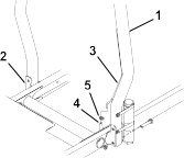
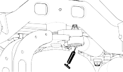
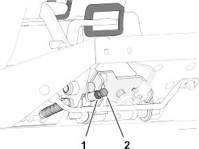
Adjusting Mow Ground Speed
-
Prepare the machine for maintenance.
-
Loosen the jam nut for the speed-stop bolt .
-
Adjust the speed-stop bolt as follows:
Note: The mow speed is set at the factory to 9.7 km/h (6 mph).
- To decrease the mow speed, rotate the speed-stop bolt clockwise.
- To increase the mow speed, rotate the speed-stop bolt counterclockwise.
-
Hold the speed-stop bolt and tighten the jam nut.
-
Test drive the machine to confirm the maximum mow speed adjustment.
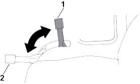
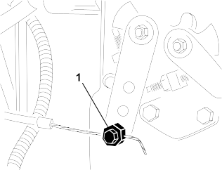
Adjusting the Throttle
-
Prepare the machine for maintenance.
-
Unlatch and open the hood.
-
Position the throttle lever rearward so that it stops against the control panel slot.
-
Loosen the throttle cable connector on the injection pump lever arm.
-
Hold the injection pump lever arm against the low idle stop and tighten the cable connector.
-
Loosen the bolts securing the throttle control to the control panel.
-
Push the throttle control lever all the way forward.
-
Slide the stop plate until it contacts the throttle lever and tighten the bolts securing the throttle control to the control
panel.
-
If the throttle does not stay in position during operation, torque the locknut used to set the friction device on the throttle
lever to 5 to 6 N∙m (44 to 53 in-lb).
Note: The maximum force required to operate the throttle lever should be 89 N (20 lb).
-
Close and latch the hood.
Hydraulic System Maintenance
Hydraulic Fluid Specifications
The reservoir is filled at the factory with high-quality hydraulic fluid. Check the level of the hydraulic fluid before you
first start the engine and daily thereafter.
Recommended hydraulic fluid: Toro PX Extended Life Hydraulic Fluid; available in 19 L (5 US gallon) pails or 208 L (55 US gallon) drums.
Note: A machine using the recommended replacement fluid requires less frequent fluid and filter changes.
Alternative hydraulic fluids: If Toro PX Extended Life Hydraulic Fluid is not available, you may use another conventional, petroleum-based hydraulic fluid having
specifications that fall within the listed range for all the following material properties and that it meets industry standards.
Do not use synthetic fluid. Consult with your lubricant distributor to identify a satisfactory product.
Note: Toro does not assume responsibility for damage caused by improper substitutions, so use products only from reputable manufacturers
who will stand behind their recommendation.
High Viscosity Index/Low Pour Point Anti-wear Hydraulic Fluid, ISO VG 46
| Material Properties: |
|
| |
Viscosity, ASTM D445 |
cSt @ 40°C (104°F) 44 to 48 |
| |
Viscosity Index ASTM D2270 |
140 or higher |
| |
Pour Point, ASTM D97 |
-37°C to -45°C (-34°F to -49°F) |
| |
Industry Specifications: |
Eaton Vickers 694 (I-286-S, M-2950-S/35VQ25 or M-2952-S) |
Note: Many hydraulic fluids are almost colorless, making it difficult to spot leaks. A red dye additive for the hydraulic fluid
is available in 20 ml (0.67 fl oz) bottles. A bottle is sufficient for 15 to 22 L (4 to 6 US gallons) of hydraulic fluid.
Order Part No. 44-2500 from your authorized Toro distributor.
Toro Premium Synthetic Biodegradable Hydraulic Fluid is the only synthetic biodegradable fluid approved by Toro. This fluid is compatible with the elastomers used in Toro hydraulic systems and is suitable for a wide-range of temperature conditions. This fluid is compatible with conventional
mineral oils, but for maximum biodegradability and performance, the hydraulic system should be thoroughly flushed of conventional
fluid. The oil is available in 19 L (5 US gallon) pails or 208 L (55 US gallon) drums from your authorized Toro distributor.
Hydraulic tank capacity
13.2 L (3.5 US gallons)
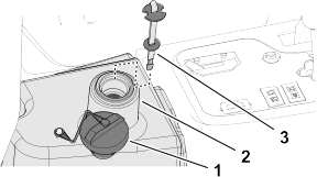
Checking the Hydraulic-Fluid Level
The reservoir is filled at the factory with high-quality hydraulic fluid. The best time to check the hydraulic oil is when
the fluid is cold. The machine should be in its transport configuration.
-
Prepare the machine for maintenance.
-
Clean the area around the filler neck and cap of the hydraulic-fluid tank and remove the cap.
-
Remove the dipstick from the filler neck and wipe it with a clean rag.
-
Insert the dipstick into the filler neck; then remove it and check the fluid level.
Note: The fluid level should be within 6 mm (1/4 inch) of the mark on the dipstick.
-
If the level is low, add the specified fluid to raise the level to the full mark.
Do not overfill the hydraulic reservoir.
-
Install the dipstick and cap onto the filler neck.
Inspecting the Hydraulic Lines and Hoses
-
Inspect the hydraulic lines and hoses for leaks, kinked lines, loose mounting supports, wear, loose fittings, weather deterioration,
and chemical deterioration.
Note: Make all necessary repairs before operating.
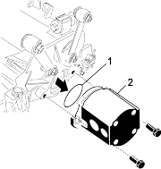
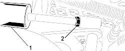
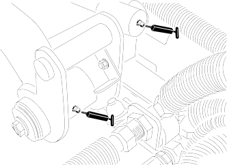
Changing the Hydraulic Fluid
|
Warning |
|
Hot hydraulic fluid can cause severe burns, which could result in death or serious injury.
Allow the hydraulic fluid to cool before performing any maintenance to the hydraulic system.
If the fluid becomes contaminated, contact your authorized Toro distributor because the system must be flushed. Contaminated fluid looks milky or black when compared to clean oil.
-
Prepare the machine for maintenance.
-
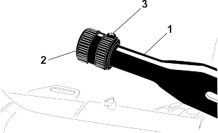
Disconnect the hydraulic hose or remove the hydraulic filter and drain the hydraulic fluid into a drain pan.
G417014
- Filter head fitting
- Hose clamp
- Hydraulic hose
G417015
- Hydraulic filter
- Filter head
-
Install the hydraulic hose when hydraulic fluid stops draining.
-
Fill the tank with the specified hydraulic fluid.
Use only the hydraulic fluids specified. Other fluids could cause system damage.
G417013
- Cap
- Filler neck (hydraulic-fluid reservoir)
- Dipstick
-
Install the dipstick and cap onto the filler neck.
-
Start the engine and use all hydraulic controls to distribute the hydraulic fluid throughout the system.
-
Check for leaks and then shut off the engine.
-
Check the fluid level and add enough to raise the level to full mark on the dipstick.
Do not overfill the reservoir.
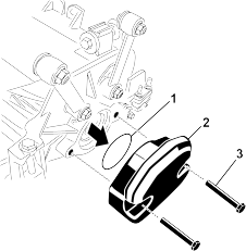
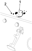
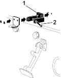
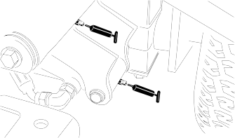
Changing the Hydraulic Filter
|
Warning |
|
Hot hydraulic fluid can cause severe burns, which could result in death or serious injury.
Allow the hydraulic fluid to cool before performing any maintenance to the hydraulic system.
Use a genuine Toro replacement filter (Part No. 86-3010).
Use of any other filter may void the warranty on some components.
-
Prepare the machine for maintenance.
-
Clean around the filter mounting area . Place a drain pan under the filter and remove the filter.
-
Lubricate the new filter gasket and fill the filter with hydraulic fluid.
-
Ensure that the filter mounting area is clean. Screw the filter on until the gasket contacts the mounting plate; then tighten
the filter 1/2 turn.
-
Start the engine and let it run for about 2 minutes to purge air from the system. Shut off the engine and check for leaks.
Cutting Unit Maintenance
Checking the Reel-to-Bedknife Contact
-
Check the reel-to-bedknife contact even if the quality of cut had been acceptable previously.
Note: There must be light contact across the full length of the reel and bedknife.
Backlapping the Cutting Units
|
Warning |
|
Contact with the cutting units or other moving parts could result in death or serious injury.
- Keep your fingers, hands, and clothing away from the cutting units and other moving parts.
- Never attempt to turn the cutting units by hand or foot while the engine is running.
Note: Additional instructions and procedures on backlapping are available in the Toro Reel Mower Basics (with sharpening guidelines), Form 09168SL.
Preparing the Machine
-
Prepare the machine for maintenance.
-
Make the initial reel-to-bedknife adjustments appropriate for backlapping; refer to the cutting unit Operator's Manual.
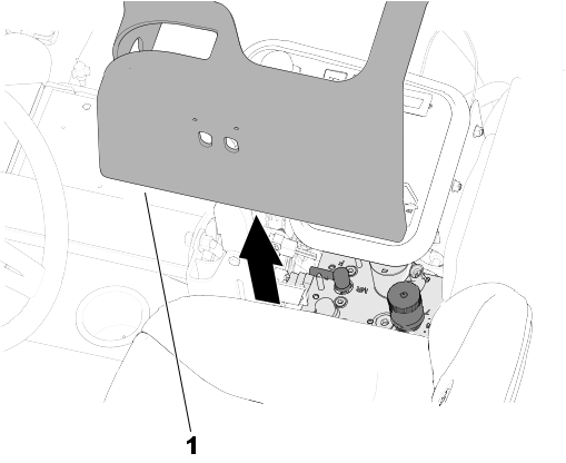
-
Lift the magnetically mounted console cover to expose the mower manifold.
-
Move the backlap lever to the R (backlap) position.
G417036
- Backlap control
- Reel speed control
Lapping the Reels and Bedknife
|
Warning |
|
Changing the engine speed while backlapping may cause the cutting units to stall, which could result in death or serious injury.
- Never change the engine speed while backlapping.
- Backlap only at idle engine speed.
Note: The seat switch is bypassed when the backlap control is in the backlap position. You do not need to be in the seat, but the
parking brake must be engaged for the engine to run.
-
Start the engine and allow it to run at low idle speed.
-
Press the cutting unit drive switch to the Engage position.
-
Apply lapping compound to the reel with a long-handle brush.
|
Danger |
|
Contacting the cutting units when they are moving will result in death or serious injury.
To avoid personal injury, ensure that you are clear of the cutting units before proceeding.
Never use a short-handled brush.
-
If you need to make an adjustment to the cutting units while backlapping, perform the following steps:
-
Press the cutting unit drive switch to the Disengage position.
-
Shut off the engine and remove the key.
-
Adjust to the cutting units.
-
Repeat steps 1 through 3.
-
Repeat Step 3 for the other cutting units that you want to backlap.
Finishing Backlapping
-
Press the cutting unit control switch to the Disengage position.
-
Shut off the engine.
-
Move the backlap lever to the F (mow) position.
If you do not change backlap lever to the F (mow) position after backlapping, the cutting units will not function properly.
G417036
-
Backlap lever
-
Reel speed control knob
-
Install the console cover to the control console.
-
Wash all lapping compound off from the cutting units.
-
For a better cutting edge, run a file across the front face of the bedknife after lapping.
Note: This removes any burrs or rough edges that may have built up on the cutting edge.
Chassis Maintenance
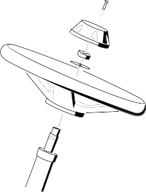
Inspecting the Seat Belt
-
Inspect the seat belt for wear, cuts, and other damage. Replace the seat belt(s) if any component does not operate properly.
-
Clean the seat belt as necessary.
Cleaning
Washing the Machine
-
Wash the machine as needed using water alone or with a mild detergent. You may use a rag when washing the machine.
- Do not use brackish or reclaimed water to clean the machine.
- Do not use power-washing equipment to wash the machine. Power-washing equipment may damage the electrical system, loosen important
decals, or wash away necessary grease at friction points. Avoid excessive use of water near the control panel, engine, and
battery.
- Do not wash the machine with the engine running. Washing the machine with the engine running may result in internal engine
damage.
Storing the Machine
-
Park the machine on a level surface, lower the cutting units, engage the parking brake, shut off the engine, and remove the
key.
-
Thoroughly clean the traction unit, cutting units, and the engine.
-
Check the tire pressure.
-
Check all fasteners for looseness; tighten them as necessary.
-
Grease or oil all grease fittings and pivot points. Wipe up any excess lubricant.
-
Lightly sand and use touch-up paint on painted areas that are scratched, chipped, or rusted. Repair any dents in the metal
body.
-
Service the battery and cables as follows:
-
Remove the battery terminals from the battery posts.
-
Clean the battery, terminals, and posts with a wire brush and baking-soda solution.
-
Coat the cable terminals and battery posts with Grafo 112X skin-over grease (Toro Part No. 505-47) or petroleum jelly to prevent corrosion.
-
Slowly charge the battery every 60 days for 24 hours to prevent lead sulfation of the battery.
-
Prepare the engine as follows:
-
Drain the engine oil from the oil pan and install the drain plug.
-
Remove and discard the oil filter. Install a new oil filter.
-
Fill the engine with specified motor oil.
-
Start the engine and run it at idle speed for approximately 2 minutes.
-
Shut off the engine and remove the key.
-
Flush the fuel tank with fresh, clean fuel.
-
Secure all the fuel-system fittings.
-
Thoroughly clean and service the air-cleaner assembly.
-
Seal the air-cleaner inlet and the exhaust outlet with weatherproof tape.
-
Check the antifreeze protection and add a 50/50 solution of water and ethylene glycol antifreeze as needed for the expected
minimum temperature in your area.
Storing the Battery
If you are storing the machine for more than 30 days, remove the battery and charge it fully. Either store it on the shelf
or on the machine. Leave the cables disconnected if they are stored on the machine. Store the battery in a cool atmosphere
to avoid quick deterioration of the charge in the battery. To prevent the battery from freezing, ensure that it is fully charged.
The specific gravity of a fully charged battery is 1.265 to 1.299.
Using the Standard Control Module (SCM)
The Standard Control Module is a potted electronic device produced in a one-size-fits-all configuration. The module uses solid
state and mechanical components to monitor and control standard electrical features required for safe product operation.
The module monitors inputs including neutral, parking brake, PTO, start, backlap, and high temperature. The module energizes
outputs including PTO, Starter, and ETR (energize to run) solenoid.
The module is divided into inputs and outputs. Inputs and outputs are identified by green LED indicators mounted on the printed
circuit board.
The start circuit input is energized by 12 VDC. All other inputs are energized when the circuit is closed to ground. Each
input has a LED that is illuminated when the specific circuit is energized. Use the input LEDs for switch and input circuit
troubleshooting.
Output circuits are energized by an appropriate set of input conditions. The 3 outputs include PTO, ETR, and START. Output
LEDs monitor relay condition indicating the presence of voltage at 1 of 3 specific output terminals.
Output circuits do not determine output device integrity, so electrical troubleshooting includes output LED inspection and
conventional device and wire harness integrity testing. Measure the disconnected component impedance, the impedance through
wire harness (disconnect at SCM), or by temporarily ”test energizing” the specific component.
The SCM does not connect to an external computer or handheld device, cannot be re-programmed, and does not record intermittent
fault troubleshooting data.
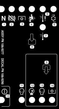
The decal on the SCM only includes symbols. Three LED output symbols are shown in the output box. All other LEDs are inputs.
The chart below identifies the symbols.
G417043
-
Inputs
-
Backlap
-
High temperature
-
In seat
-
PTO switch
-
Parking brake off
-
Neutral
-
PTO
-
Start
-
ETR
-
Power
-
Outputs
Troubleshooting the Standard Control Module (SCM)
-
Determine the output fault you are trying to resolve (PTO, START, or ETR).
-
Move the key switch to the On position and ensure that the red power LED is illuminated.
-
Move all the input switches to ensure that all LEDs change state.
-
Position the input devices at the appropriate position to achieve the appropriate output. Use the following logic chart to
determine the appropriate input condition.
-
If the specific output LED is illuminated without the appropriate output function, check the output harness, connections,
and component. Repair as needed.
-
If the specific output LED is not illuminated, check both fuses.
-
If the specific output LED is not illuminated and the inputs are in the appropriate condition, install a new SCM and determine
if the fault disappears.
Note: Each row (across) in the logic chart that follows identifies input and output requirements for each specific product function.
The product functions are listed in the left column. The symbols identify the specific circuit condition including energized
to voltage, closed to ground, and open to ground.
Logic Chart
|
Start
|
—
|
—
|
+
|
O
|
O
|
—
|
O
|
O
|
+
|
+
|
O
|
|
Run (Off Unit)
|
—
|
—
|
O
|
O
|
O
|
O
|
O
|
O
|
O
|
+
|
O
|
|
Run (On Unit)
|
—
|
O
|
O
|
—
|
O
|
—
|
O
|
O
|
O
|
+
|
O
|
|
Mow
|
—
|
O
|
O
|
—
|
—
|
—
|
O
|
O
|
O
|
+
|
+
|
|
Backlap
|
—
|
—
|
O
|
O
|
—
|
O
|
O
|
—
|
O
|
+
|
+
|
|
Hi Temp
|
—
|
|
O
|
|
|
|
—
|
|
O
|
O
|
O
|
- (–) Indicates a circuit closed to ground—LED ON.
- (O) Indicates a circuit open to ground or de-energized—LED OFF.
- (+) Indicates an energized circuit (clutch coil, solenoid, or start input)—LED ON.
- A blank indicates a circuit that is not involved with the logic.
To troubleshoot, turn on the key without starting the engine. Identify the specific function that does not work and work across
the logic chart. Inspect the condition of each input LEDs to ensure that it matches the logic chart.
If the input LEDs are correct, check the output LED. If the output LED is illuminated but the device is not energized, measure
the available voltage at the output device, the continuity of the disconnected device, and the potential voltage on the ground
circuit (floating ground). Repairs will vary depending on your findings.