


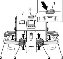
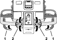
 indicates
the menu item is accessed by entering the PIN.
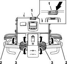
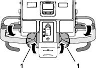
indicates
the menu item is accessed by entering the PIN.| Maintenance Service Interval | Maintenance Procedure |
|---|---|
| Before each use or daily |
|
Introduction
A walking operator controls this machine, and it is intended to be used by professional, hired operators in commercial applications. The machine is designed primarily for aerating large areas on well-maintained lawns in parks, golf courses, sports fields, and on commercial grounds. Using this product for purposes other than its intended use could prove dangerous to you and bystanders.
Read this information carefully to learn how to operate and maintain your product properly and to avoid injury and product damage. You are responsible for operating the product properly and safely.
Visit www.Toro.com for product safety and operation training materials, accessory information, help finding a dealer, or to register your product.
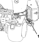
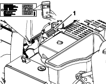
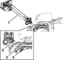
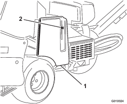
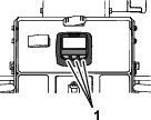
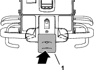
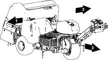
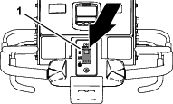
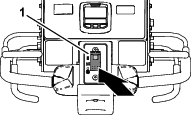
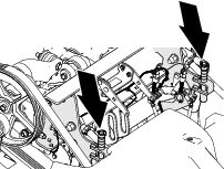
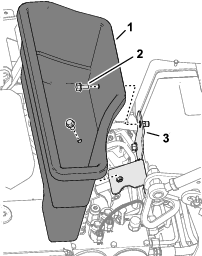
Whenever you need service, genuine Toro parts, or additional information, contact an Authorized Service Dealer or Toro Customer Service and have the model and serial numbers of your product ready. Figure 1 identifies the location of the model and serial numbers on the product. Write the numbers in the space provided.
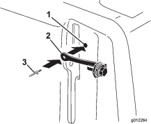
This manual identifies potential hazards and has safety messages identified by the safety-alert symbol (Figure 2), which signals a hazard that may cause serious injury or death if you do not follow the recommended precautions.

This manual uses 2 words to highlight information. Important calls attention to special mechanical information and Note emphasizes general information worthy of special attention.
This product complies with all relevant European directives; for details, please see the separate product specific Declaration of Conformity (DOC) sheet.
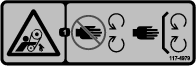
Because in some areas there are local, state, or federal regulations requiring that a spark arrester be used on the engine of this machine, a spark arrester is available as an option. If you require a spark arrester, contact your Authorized Service Dealer. Genuine Toro spark arresters are approved by the USDA Forestry Service.
The enclosed engine owner's manual is supplied for information regarding the US Environmental Protection Agency (EPA) and the California Emission Control Regulation of emission systems, maintenance, and warranty. Replacements may be ordered through the engine manufacturer.
Warning
CALIFORNIA
Proposition 65 Warning
The engine exhaust from this product contains chemicals known to the State of California to cause cancer, birth defects, or other reproductive harm.
Battery posts, terminals, and related accessories contain lead and lead compounds, chemicals known to the State of California to cause cancer and reproductive harm. Wash hands after handling.
Use of this product may cause exposure to chemicals known to the State of California to cause cancer, birth defects, or other reproductive harm.
Safety
General Safety
This product is capable of causing personal injury. Always follow all safety instructions to avoid serious personal injury.
-
Read and understand the contents of this Operator’s Manual before starting the engine.
-
Use your full attention while operating the machine. Do not engage in any activity that causes distractions; otherwise, injury or property damage may occur.
-
Do not put your hands or feet near moving components of the machine.
-
Do not operate the machine without all guards and other safety protective devices in place and working on the machine.
-
Keep the machine away from bystanders while it is moving.
-
Keep clear of the opening around the tines. Keep bystanders and pets away from the machine.
-
Keep children out of the operating area. Never allow children to operate the machine.
-
Park the machine on a level surface, fully raise and latch the handlebar to engage the parking brake, shut off the engine, remove the key, and wait for all moving parts to stop before servicing, fueling, or unclogging the machine.
Improperly using or maintaining this machine can result in injury.
To reduce the potential for injury, comply with these safety instructions
and always pay attention to the safety-alert symbol  , which means Caution, Warning,
or Danger—personal safety instruction. Failure to comply with
these instructions may result in personal injury or death.
, which means Caution, Warning,
or Danger—personal safety instruction. Failure to comply with
these instructions may result in personal injury or death.
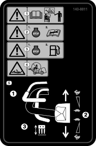
Safety and Instructional Decals
 |
Safety decals and instructions are easily visible to the operator and are located near any area of potential danger. Replace any decal that is damaged or missing. |


Setup
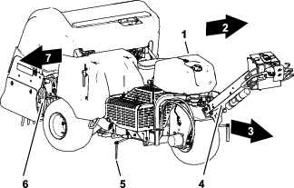
Note: The front of the machine is located at the operator handle, and is the normal operator position. Left and right are in relation to the direction of travel as you walk with machine following you.
Note: To raise the coring head after uncrating the machine, release the aerate bail and start the engine; refer to Starting the Engine and Raising the Coring Head for more information.
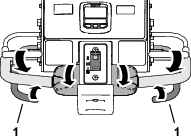
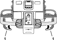
Installing the Rear Wheels
Parts needed for this procedure:
| Wheel assembly | 2 |
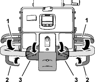
Note: If available, use a hoist to lift the rear of the machine. Use the eyelets in the coring-head bearing housings as hoist attachment points (Figure 3).
-
At the rear of the machine, remove the 4 lug nuts that secure the rear of the machine to brackets of the shipping pallet.
-
Assemble a wheel assembly onto each rear-wheel hub with the 4 lug nuts (Figure 4).
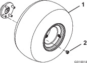
-
Torque the lug nuts to 61 to 75 N∙m (45 to 55 ft-lb).
-
Repeat steps 1 though 3 at the other side of the machine.
-
Deflate all tires to 83 kPa (12 psi).
Installing the Handle
Parts needed for this procedure:
| Handle | 1 |
| Locknut (1/2 inch) | 3 |
Assembling the Handle to the Machine
-
Insert the studs at the end of the handlebar into the holes in the steering arm (Figure 5).
Note: Have another person help hold the handlebar.
-
Thread a flange locknut (1/2 inch) onto each of the 3 studs.
-
Torque the flange locknuts to 91 to 113 N∙m (67 to 83 ft-lb).
-
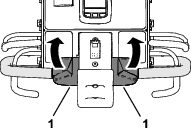
Rotate the handlebar up and secure it with the handlebar-latch pin (Figure 6).
Assembling the Brake Cable
-
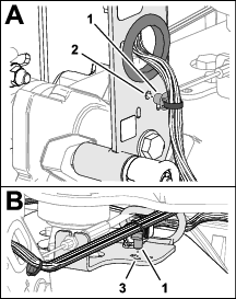
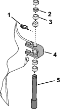
Route the fitting of the brake cable under the bottom of the handle-bar channel (Figure 7).
-
Assemble the brake-cable fitting on to the clevis pin, and secure the fitting to the pin with the washer and hairpin.
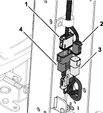
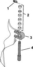
Connecting the Wire Harness
-
Route the 6-pin connector and the 12-pin connector of the machine wire harness through the grommet in the handle-bar channel (Figure 8).
-
Plug the 12-pin connector of the machine harness into the 12-socket connector of the handlebar wire harness (Figure 9).
-
Plug the 6-pin connector of the machine harness into the 6-socket connector of the handlebar harness.
-
Insert the push-in anchor of the machine harness into the hole in the handle-bar channel (Figure 10).
-
Insert the push-in anchor of the machine harness into the hole in the guide bracket.
-
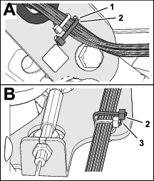
Secure the machine harness to the handle-bar channel with a cable tie through the slots in the channel (Figure 11).
-
Secure the machine harness to the guide bracket with a cable tie through the slots in the bracket.
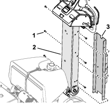
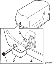
Installing the Handlebar Cover
-
Align the small notch in the handlebar cover with the notch up (Figure 12).
-
Align the holes in the cover with the holes in the handle-bar channel.
-
Secure the cover to the handlebar with the 6 thread-forming screws (1/4 inch).
Charging and Connecting the Battery
Parts needed for this procedure:
| Bolt (1/4 x 1 inch) | 2 |
| Flange nut (5/16 inch) | 2 |
Charging the Battery
Danger
Battery electrolyte contains sulfuric acid which is a deadly poison and causes severe burns.
-
Avoid contact with skin, eyes, or clothing. Wear safety glasses to shield your eyes and rubber gloves to protect your hands.
-
Remove, charge, and install the battery where clean water is always available for flushing the skin.
Warning
Charging the battery produces gasses that can explode.
Never smoke near the battery and keep sparks and flames away from it.
Warning
Battery terminals or metal tools could short against metal machine components, causing sparks. Sparks can cause the battery gasses to explode, resulting in personal injury.
-
When removing or installing the battery, do not allow the battery terminals to touch any metal parts of the machine.
-
Do not allow metal tools to short between the battery terminals and metal parts of the machine.
Warning
Incorrect battery cable routing could damage the machine and cables, causing sparks. Sparks can cause the battery gasses to explode, resulting in personal injury.
-
Always disconnect the negative (black) battery cable before disconnecting the positive (red) cable.
-
Always connect the positive (red) battery cable before connecting the negative (black) cable.
-
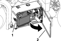
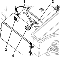
Unlatch and open the battery-compartment door (Figure 13).
-
Remove the battery from the battery compartment.
-
Use a battery charger with a 3 to 4 A charging capacity to charge the battery.
-
When the battery is charged, disconnect the charger from the electrical outlet and battery posts.
Installing the Battery
-
Assemble the battery into the tray in the battery compartment (Figure 14). Position the battery so that the terminals are aligned the outward.
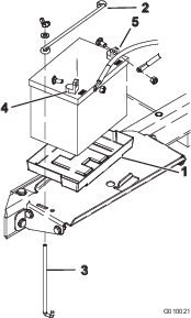
-
Secure the battery to the compartment base with a hold-down rod, 2 J-rods, 2 flat washers, and 2 wing nuts.
-
Secure the positive cable (red) to the positive (+) battery terminal with a carriage bolt and nut.
-
Slide the rubber boot over the positive terminal.
-
Secure the negative cable (black) to the negative (–) terminal of the battery with a carriage bolt and nut.
-
Close and latch the battery compartment door.
Installing the Rear Hood Latch Lock
CE Machines
Parts needed for this procedure:
| Latch lock | 2 |
| Tap bolt | 2 |
| Internal tooth lock washer | 2 |
If you are setting up this machine for use in the European Union (CE), install the hood-latch lock onto the rear hood as follows to comply with CE regulations.
-
Remove the rear hood.
-
Install a latch lock over the hood latch (Figure 15) with a tap bolt (2 total).
-
Use a pliers and a wrench to thread an internal lock washer onto each bolt (1 to 2 threads) to secure the bolts to the hood.
-
Repeat steps 2 through 3 at the other side of the hood.
-
Install the rear hood.
Installing the Belt-Cover Latch Lanyard
CE Machines
Parts needed for this procedure:
| Lanyard | 1 |
| Pop rivet | 1 |
| Bolt (1/4 x 1 inch) | 1 |
| Locknut (1/4 inch) | 1 |
If you are setting up this machine to be compliant with CE, Install the belt cover latch link as follows.
-
Locate the hole in the belt cover next to the slot for the latch lever (Figure 16 and Figure 17).
-
Secure the lanyard assembly to the hole in the belt cover with a pop rivet (Figure 17).
-
Thread the bolt into the latch lever (Figure 18).
Applying the CE Decal and the Production Year Decal
Installing the Tine Holders, Turf Guards, and Tines
A wide selection of tine holders, turf guards, and tines are available for the machine. Refer to Installing Turf Guards, Tine Holders, and Tines.
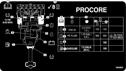
Product Overview
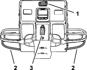
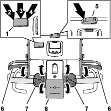
Handlebar Controls
Handle-Bar Latch
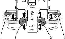
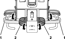
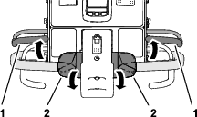
Use the handle-bar latch (Figure 21) to secure the handlebar in the upward position and to engage the parking brake.
Important: Secure the handlebar in the up position anytime you leave the operator’s position.
Operator-Presence Bail
The operator-presence bail (Figure 21) helps ensure that you are in the operator’s position while driving the machine or running the coring head.
Note: Releasing the operator-presence bail does not shut off the engine.
The InfoCenter
Use the InfoCenter (Figure 21) to adjust how the coring head controls work.
Bump-Stop Switch
If you contact the bump-stop switch (Figure 21), the machine performs the following actions:
-
The machine stops driving forward.
-
The coring head raises and stops running.
Note: Contacting the bump-stop switch does not shut off the engine. You can drive the machine in the reverse direction, but you must reset the bump switch to drive forward.
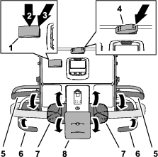
Traction Controls
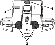
Transport/Aeration Switch
Use the transport/aeration switch (Figure 22) to control the maximum speed you can drive the machine while aerating or transporting the machine.
-
The AERATION position allows aeration and limits ground speed to 4.0 kph (2.5 mph) or slower.
-
The TRANSPORT position allows you to drive the machine at full ground speed or slower between job sites.
Note: You cannot aerate with the transport/aeration switch in the TRANSPORT position.
Traction Controls
Use the left or right traction control (Figure 22) to drive the machine forward or backward.
Speed-Lock Switch—Transport Mode
Use the speed-lock switch (Figure 22) to maintain the ground speed at which you drive the machine; similar to cruise control in an automobile.
-
The ENGAGE position locks the current ground speed at which the machine is driving.
-
The ON position activates the ground-speed lock.
-
The OFF position shuts off the ground-speed lock.
Speed-Lock Switch—Aerate Mode
Use the speed-lock switch (Figure 22) to maintain the ground speed at the aeration hole spacing rate.
-
The ON position—activates and engages the ground-speed lock to maintain the ground speed at the aeration hole spacing rate when you release the aerate bail at the end of an aeration pass.
-
The OFF position shuts off the ground-speed lock—the machine stops moving forward when you release the aerate bail.
Coring Head Controls
Engine Controls
Throttle Lever
Use the throttle lever (Figure 24) to control the engine speed:
-
Moving throttle lever forward increases engine speed—toward the FAST position.
-
Moving throttle lever backward decreases engine speed—toward the SLOW position.
Note: The engine speed regulates the speed of the coring head.
Choke
Use the choke when starting a cold engine (Figure 24).
Ignition Switch and Key
Use the ignition switch (Figure 24) to start and shut off the engine. The switch has 3 positions:
-
START—rotate key clockwise to the START position to engage the starter motor.
-
RUN—when the engine starts, release the key and it moves automatically to the ON position.
-
OFF—rotate the key counterclockwise to the OFF position to shut off the engine.
Tachometer
Use the tachometer to determine the engine speed (Figure 24).
Fuel-Shutoff Valve
Use the fuel-shutoff valve to control fuel from the fuel tank (Figure 25).
Using the InfoCenter LCD Display
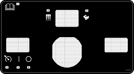
The InfoCenter LCD display shows information about your machine, such as the operating status and various diagnostics (Figure 26). When you first power the electrical system, a splash screen appears briefly, and then the main information screen of the InfoCenter. You can switch between the splash screen and main information screen at any time by pressing any of the InfoCenter buttons and then selecting the appropriate directional arrow.
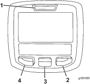
-
Left Button, Menu Access/Back Button—press this button to access the InfoCenter menus. You can use it to exit any menu that you are currently using.
-
Middle Button—use this button to scroll down menus.
-
Right Button—use this button to open a menu where a right arrow indicates additional content.
Note: The purpose of each button may change depending on what is required at the time. Each button is labeled with an icon displaying its current function.
|
SERVICE DUE |
Indicates when scheduled service should be performed |
|
|
Info icon |
|
|
InfoCenter |
|
|
Hole depth |
|
|
Hole spacing |
|
|
Tine diameter |
|
|
Tines per holder |
|
|
Transport mode |
| Symbols are often combined to form sentences. Some examples are shown below. | |
 | Operator should put the traction control in neutral |
 | Engine start is denied |
 | Engine shutdown |
 | PTO denied |
|
|
|
Using the Menus
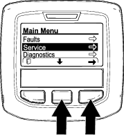
To access the InfoCenter menu system, press the menu access button while at the main screen. This displays the main menu. Refer to the following tables for a list of the options available from the menus:
|
Menu Item |
Description |
|---|---|
|
Faults |
Contains a list of the recent machine faults. Refer to the Service Manual or your authorized the manufacturer distributor for more information on the Faults menu and the information contained there. |
|
Service |
Contains information on the machine such as hours of use, counters, and other similar numbers. |
|
Diagnostics |
Lists various states that the machine currently has; you can use this to troubleshoot certain issues as it quickly tells you which machine controls are active, and which are shutoff. |
|
Statistics |
Lists counters for machine run data and operations data, such as information, such as engine run time, aeration area/volume/time, aeration travel distance. |
|
Settings |
Allows you to customize and modify configuration variables on the InfoCenter display. |
|
About |
Lists the model number, serial number, and software version of your machine. |
|
Menu Item |
Description |
|---|---|
|
Hours |
Displays the total number of hours that the machine, engine, and PTO have been on, as well as the number of hours the machine has been transported and service due |
|
Counts |
Displays numerous counts the machine experienced |
|
Traction |
Displays if the sensor calibrations are valid, starts the calibration process, and lists the electrical value of the sensor. |
|
Ground Height |
Displays if the sensor calibrations are valid, starts the calibration process, and lists the electrical value of the sensor. |
|
Bail |
Displays if the sensor calibrations are valid, starts the calibration process, and lists the electrical value of the sensor. |
|
Height Sensor |
Displays if the sensor calibrations are valid, starts the calibration process, and the lists electrical value of the sensor. |
|
Menu Item |
Description |
|---|---|
|
Units |
Controls the units used on the InfoCenter (English or metric) |
|
Language |
Controls the language used on the InfoCenter* |
|
LCD Backlight |
Controls the brightness of the LCD display |
|
LCD Contrast |
Controls the contrast of the LCD display |
|
Protected Menus |
Allows an authorized person with the PIN code to access protected menus |
|
Protect Settings |
Allows the ability to change the settings in the protected settings |
|
Max Speed |
Allows the ability to change the maximum forward ground speed—default = 6.4 kph (4 mph) |
|
|
|
|
Menu Item |
Description |
|---|---|
|
Model |
Lists the model number of the machine |
|
SN |
Lists the serial number of the machine |
|
Machine Controller Revision |
Lists the software revision of the master controller |
|
InfoCenter Revision |
Lists the software revision of the InfoCenter |
|
CAN Bus | Lists the machine communication bus status |
|
|
|
|
Menu Item |
Description |
|---|---|
|
Engine Run |
Refer to the Service Manual or your authorized Toro distributor for more information on the Engine Run menu and the information contained there. |
|
PTO |
|
|
Traction |
Protected Menus
There are 3 protected operating settings within the Settings Menu of the InfoCenter: Max Speed, Area 2—Area, Area 2—Volume. These settings are unlocked by using the Accessing Protected Menus procedure.
Note: At the time of delivery, your distributor may have changed the PIN code.
Accessing Protected Menus
Note: The factory default PIN code for you machine is either 0000 or 1234.If you changed the PIN code and forgot the code, contact your authorized Toro distributor for assistance.
-
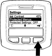
From the MAIN MENU, use the center button to scroll down to the SETTINGS MENU and press the right button (Figure 27).
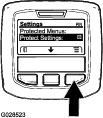
-
In the SETTINGS MENU, use the center button to scroll down to the PROTECTED MENU and press the right button (Figure 28A).
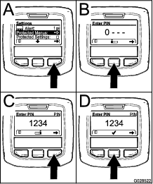
-
To enter the PIN code, press the center button until the correct first digit appears, then press the right button to move on to the next digit (Figure 28B and Figure 28C). Repeat this step until the last digit is entered and press the right button once more.
-
Press the middle button to enter the PIN code (Figure 28D).
Wait until the red indicator light of the InfoCenter illuminates.
Note: If the InfoCenter accepts the PIN code and the protected menu is unlocked, the word “PIN” displays in the upper right corner of the screen.
Note: Rotate the key switch to the OFF position and then to the ON position locks the protected menu.
You can view and change the settings in the Protected Menu. Once you access the Protected Menu, scroll down to Protect Settings option. Use the right button to change the setting. Setting the Protect Settings to OFF allows you to view and change the settings in the Protected Menu without entering the PIN code. Setting the Protect Settings to ON hides the protected options and requires you to enter the PIN code to change the setting in the Protected Menu. After you set the PIN code, rotate the key switch OFF and back to the ON position to enable and save this feature.
Note: Specifications and design are subject to change without notice.
| Width | 127 cm (50.1 inches) |
| Wheelbase | 113 cm (44.5 inches) |
| Track width | 97 cm (38.3 inches) |
| Coring width | 122 cm (48 inches) |
| Length | 295 cm (116.3 inches) |
| Head height (raised) | 114 cm (45 inches) |
| Head height (lowered) | 93 cm (36.5 inches) |
| Height, handle | 154.2 cm (60.7 inches) |
| Ground clearance | 12 cm (4.8 inches) |
| Forward speed | 0 to 7.2 kph (0 to 4.5 mph) |
| Reverse speed | 0 to 4 kph (0 to 2.5 mph) |
| Net weight | 745 kg (1,642 lbs) |
Attachments/Accessories
A selection of Toro approved attachments and accessories is available for use with the machine to enhance and expand its capabilities. Contact your Authorized Service Dealer or authorized Toro distributor or go to www.Toro.com for a list of all approved attachments and accessories.
To ensure optimum performance, use only genuine Toro replacement parts and accessories. Replacement parts and accessories made by other manufacturers could be dangerous, and such use could void the product warranty.
Refer to the tine configuration table that follows for the tine head, turf guard, and tine information:
| Tine Head Description | Tine Head Spacing | Shank Size | Tine Quantity | Turf Guard Type (quantity) |
|---|---|---|---|---|
| 2x5 Mini-Tine Head | 41 mm (1.60 inch) | 9.5 mm (3/8 inch) | 60 | 5-Tine—short (2) |
| 5-Tine—long (1) | ||||
| 1x6 Mini-Tine Head | 32 mm (1.25 inch) | 9.5 mm (3/8 inch) | 36 | 6-Tine—short (2) |
| 6-Tine—long (1) | ||||
| 3 Tine Head (7/8 inch) | 66 mm (2.60 inch) | 22.2 mm (7/8 inch) | 18 | 3-Tine—short (2) |
| 3-Tine—long (1) | ||||
| 3 Tine Head (3/4 inch) | 66 mm (2.60 inch) | 19.5 mm (3/4 inch) | 18 | 3-Tine—short (2) |
| 3-Tine—long (1) | ||||
| 4 Tine Head (3/4 inch) | 51 mm (2.00 inch) | 19.5 mm (3/4 inch) | 24 | 4-Tine—short (2) |
| 4-Tine—long (1) | ||||
| 5 Needle-Tine Head | 41 mm (1.60 inch) | — | 30 | 5-tine—short (2) |
| 5-Tine—long (1) |
Operation
Note: Determine the left and right sides of the machine from the normal operating position.
Before Operation
Before Operation Safety
General Safety
-
Never allow children or untrained people to operate or service the machine. Local regulations may restrict the age of the operator. The owner is responsible for training all operators and mechanics.
-
Become familiar with the safe operation of the equipment, operator controls, and safety signs.
-
Know how to stop the machine and shut off the engine quickly.
-
Before operating, always inspect the machine to ensure that the tines are in good working condition. Replace worn or damaged tines.
-
Inspect the area where you plan to use the machine and remove all objects that the machine could strike.
-
Locate and mark all electrical or communication lines, irrigation components, and other obstructions in the area to be aerated. Remove the hazards, if possible, or plan how to avoid them.
-
Park the machine on a level surface, fully raise and latch the handlebar to engage the parking brake, shut off the engine, remove the key, and wait for all moving parts to stop.
-
Check that operator-presence controls, safety switches, and shields are attached and functioning properly. Do not operate the machine unless they are functioning properly.
Fuel Safety
-
Use extreme care in handling fuel. It is flammable and its vapors are explosive.
-
Extinguish all cigarettes, cigars, pipes, and other sources of ignition.
-
Use only an approved fuel container.
-
Do not remove the fuel cap or fill the fuel tank while the engine is running or hot.
-
Do not add or drain the fuel in an enclosed space.
-
Do not store the machine or fuel container where there is an open flame, spark, or pilot light, such as on a water heater or other appliance.
-
If you spill fuel, do not attempt to start the engine; avoid creating any source of ignition until the fuel vapors have dissipated.
Adding Fuel
Fuel Specification
| Type | Unleaded gasoline |
| Minimum octane rating | 87 (US) or 91 (research octane; outside the US) |
| Ethanol | No more than 10% by volume |
| Methanol | None |
| MTBE (methyl tertiary butyl ether) | Less than 15% by volume |
| Oil | Do not add to the fuel |
Use only clean, fresh (no more than 30 days old), fuel from a reputable source.
Important: To reduce starting problems, add fuel stabilizer/conditioner to fresh fuel as directed by the fuel-stabilizer/conditioner manufacturer.
Filling the Fuel Tank
Fuel tank capacity: 26.5 L (7 US gallons)
-
Park the machine on a level surface, fully raise and latch the handlebar to engage the parking brake, shut off the engine, remove the key, and wait for all moving parts to stop.
-
Clean around the fuel-tank cap and remove it (Figure 29).
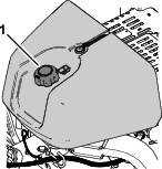
-
Add fuel to the fuel tank, until the level is 6 mm to 13 mm (1/4 to 1/2 inch) below the bottom of the filler neck.
Important: This space in the tank allows fuel to expand. Do not fill the fuel tank completely full.
-
Install the fuel-tank cap securely.
-
Wipe up any spilled fuel.
Performing Daily Maintenance
Before starting the machine each day, perform the each Use/Daily procedure listed in .
Testing the Safety Interlock System
Caution
If safety interlock system is disconnected or damaged, the machine could operate unexpectedly, causing personal injury.
-
Do not tamper with the interlock switches.
-
Check the operation of the interlock system daily and replace any damaged safety-interlock parts before operating the machine.
-
The safety interlock system prevents the engine from starting unless the traction control is in the NEUTRAL position.
-
The safety interlock system prevents the engine from starting unless the operator presence bail is fully released.
-
The safety interlock system prevents the engine from starting unless the coring head bail is fully released.
-
The safety interlock system raises the coring head and shuts it off if you drive the machine backward while aerating or contact the bump-stop switch.
Important: If the safety interlock system does not operate as described, have an authorized the manufacturer distributor repair the safety interlock system immediately.
Raising the Coring Head
If the coring head is lowered, perform the following steps. If the coring head is raised, skip to Testing the Starter Interlock.
-
Start the engine and set the engine speed to the SLOW position; refer to Starting the Engine.
-
Lower the handlebar (Figure 30).
-
Press any of the buttons on the InfoCenter (Figure 31).
Note: The coring head raises.
-
Shut off the engine; refer to Shutting Off the Engine.
Testing the Starter Interlock
-
If the engine is running, shut it off.
-
Hold either operator-presence bail to the handlebar and rotate the traction control (Figure 32) forward or rotate it backward, and start the engine.
Important: The engine must not start.
Testing the Operator Presence Interlock
-
Release the operator-presence bail, move the traction control to the NEUTRAL position, and start the engine.
-
Hold either operator-presence bail to the handlebar and rotate the top of the traction control forward (Figure 33).
Note: The machine drives forward.
-
While holding the traction control, release the operator-presence bail (Figure 34).
Important: The machine must stop driving forward.
Testing the Bump-Stop Interlock
-
Hold either operator-presence bail to the handlebar and rotate the top of the traction control forward (Figure 35).
Note: The machine drives forward.
-
While holding the operator-presence bail and the traction control, contact the bump-stop switch (Figure 36).
Important: The machine must stop driving forward.
Note: The engine remains running.
-
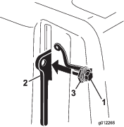
Reset the bump-stop switch; refer to Resetting the Bump-Stop Switch.
Testing the Coring Head-Reverse Interlock
-
Perform 1 of the following:
-
Move the machine to a turf area where you can aerate without damaging the tines or the area.
-
Remove the tines.
-
-
Hold either operator-presence bail to the handlebar, rotate the top of the traction control forward, and close the aerate bail (Figure 37).
Note: The machine drives forward, coring head runs, and it lowers.
-
While holding the operator-presence bail and aerate bail, rotate the top of the traction control backward (Figure 38).
Important: The coring head must raise and stop running.
Note: The engine remains running.
-
Move the traction control to the NEUTRAL position.
-
If you removed the tines, install them and calibrate the tine ground height; refer to Assembling the Tines to the Coring Head and Calibrating the Tine Ground Height.
Installing Turf Guards, Tine Holders, and Tines
Important: You must calibrate tine ground height each time you change from longer tines to shorter tines or from shorter tines to longer tines.
A wide selection of tine holders, turf guards, and tines are available for the machine. Choose the required components per the accessory chart in Attachments and Accessories.
Preparing the Machine
-
Raise the coring head and lock it in position with the service latch; refer to Supporting the Coring Head with the Service Latch.
-
Park the machine on a level surface, fully raise and latch the handlebar to engage the parking brake, shut off the engine, remove the key, and wait for all moving parts to stop.
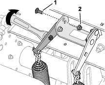
Assembling the Turf Guards
Note: The factory ships turf guard clamps, washers, and flange locknuts secured to the turf guard brackets (Figure 39).
Loosely assemble the turf guards to the turf guard brackets with 4 turf-guard clamps and 12 flange locknuts (3/8 inch) and 12 washers (7/16 x 13/16 inch).
Note: Do not tighten the flange locknuts.
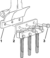
Assembling the Tine Holder
-
Loosely assemble the tine clamp to the tine holder (Figure 40) with 4 bolts (3/8 x 1-1/2 inches). Do not tighten the bolts.
Note: The bolts are parts in the tine holder kits.
-
Assemble the tines into the tine holder and tine clamp (Figure 41).
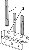
-
Torque the bolts (3/8 x 1-1/2 inches) securing the tine clamps and tines to 40.6 N∙m (30 ft-lb).
-
Repeat steps 1 through 3 for the other tine clamps, tine holders, and tines.
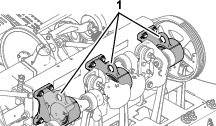
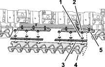
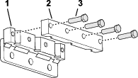
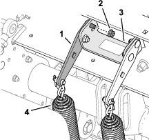
Assembling the Tines to the Coring Head
-
Loosely assemble tine holder and tines to tine arm #2 (Figure 42 and Figure 43) with 3 bolts (1/2 x 1-1/4 inches).
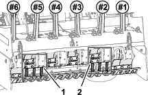
-
Torque the bolts (1/2 x 1-1/4 inches) to 102 N∙m (75 ft-lb).
-
Repeat steps 1 and 2 for tine arm #5.
-
Check the alignment of the turf guard slots to the tines to ensure that they are centered (Figure 44).
Note: Adjust the turf guards as required.
-
Torque the flange locknuts (3/8 inch) that secure the 3 turf-guard clamps and 3 turf guards to the 3 turf guard brackets.
-
Install the remaining tine holder and tines to tine holders #1, #3, #4, and #6 with 12 bolts (1/2 x 1-1/4 inches).
-
Torque the bolts (1/2 x 1-1/4 inches) to 102 N∙m (75 ft-lb).
-
Calibrate the machine for tine to ground height; refer to Running the Teach Ground Height Application.
Hole Depth, Hole Spacing, and Tine Settings
Accessing the Settings Screens
-
Rotate the ignition key to the RUN position.
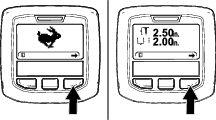
Note: The TRANSPORT mode screen or the AERATE mode screen displays (Figure 45).
-
Press the right InfoCenter button twice to display the Calibrating the Tine Ground Height screen (Figure 46).
Note: Press the left InfoCenter button to display the TRANSPORT mode screen.
-
Press the right InfoCenter button to display the Setting the Hole Depth screen (Figure 47).
Note: Press the left InfoCenter button to display the Teach Ground Height screen.
-
Press the right InfoCenter button to display the Setting the Hole Spacing screen (Figure 48).
Note: Press the left InfoCenter button to display the Setting the Hole Depth screen.

-
Press the right InfoCenter button to display the Setting the Tine Diameter screen (Figure 48).
Note: Press the left InfoCenter button to display the Setting the Hole Spacing screen.
-
Press the right InfoCenter button to display the Setting the Tine Quantity screen (Figure 50).
Note: Press the left InfoCenter button to display the Setting the Tine Diameter screen.
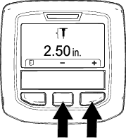
Setting the Hole Depth
-
Ensure that the coring head is raised; refer to Raising the Coring Head.
-
Rotate the ignition key to the RUN position.
-
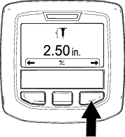
Press the right InfoCenter button until the Setting the Hole Depth screen displays (Figure 51 and Figure 52).
-
Press the center button to select the Set Depth option.
Note: The Set Depth screen displays.

-
Adjust the tine depth (Figure 53) as follows:
-
Press the InfoCenter center button to decrease hole depth.
-
Press the right button to increase hole depth.
-
-
Press the left InfoCenter button to save your setting and exit the set depth screen.
-
Rotate the ignition key to the OFF position.
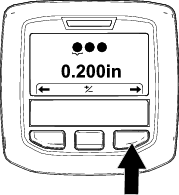
Setting the Hole Spacing
Note: When you select a target hole spacing rate, the machine controls the ground speed to maintain the hole spacing distance.
-
Ensure that the coring head is raised; refer to Raising the Coring Head.
-
Rotate the ignition key to the RUN position.
-
Press the right InfoCenter button until the Setting the Hole Spacing screen displays (Figure 54 and Figure 55).
-
Press the center button to select the Set Spacing option.
Note: The Set Spacing screen displays.
-
Adjust the hole spacing (Figure 56) as follows:
-
Press the InfoCenter center button to decrease hole spacing.
-
Press the right button to increase hole spacing.
-
-
Press the left InfoCenter button to save your setting and exit the Set Hole Spacing screen.
-
Rotate the ignition key to the OFF position.
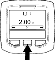
Setting Tine Diameter
-
Ensure that the coring head is raised; refer to Raising the Coring Head.
-
Rotate the ignition key to the RUN position.
-
Press the right InfoCenter button until the Setting the Tine Diameter screen displays (Figure 58).
-
Press the center button to select the Set Diameter option.
Note: The Set Diameter screen displays.
-
Adjust the tine diameter (Figure 59) as follows:
-
Press the InfoCenter center button to decrease tine diameter.
-
Press the right button to increase tine diameter.
-
-
Press the left InfoCenter button to save your setting and exit the Set Hole Spacing screen.
-
Rotate the ignition key to the OFF position.
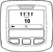
Setting the Tines Quantity
-
Ensure that the coring head is raised; refer to Raising the Coring Head.
-
Rotate the ignition key to the RUN position.
-
Press the right InfoCenter button until the Setting the Tine Quantity screen displays (Figure 61).
-
Press the center button to select the Set Quantity option.
Note: The Set Quantity screen displays.
-
Adjust the tine quantity (Figure 62) as follows:
Important: The tine quantity is the number of tines of 1 holder.
-
Press the InfoCenter center button to decrease tine quantity.
-
Press the right button to increase tine quantity.
-
-
Press the left InfoCenter button to save your setting and exit the Set Hole Spacing screen.
-
Rotate the ignition key to the OFF position.
Calibrating the Tine Ground Height
| Maintenance Service Interval | Maintenance Procedure |
|---|---|
| Before each use or daily |
|
Important: Calibrate the tine ground height each time you change tines or replace worn tines.
Preparing the Machine
-
Ensure that the coring head is raised.
-
Park the machine on a level surface, fully raise and latch the handlebar to engage the parking brake, shut off the engine, remove the key, and wait for all moving parts to stop.
-
Remove the coring-head cover; refer to Removing the Coring-Head Cover.
-
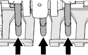
Rotate coring-head pulley (Figure 63) until the outermost tines are aligned closest to the ground (Figure 64).
Important: Keep your fingers away of the area where the belt merges and departs the pulley so that you do not pinch your fingers.
-
Install the coring-head cover; refer to Installing the Coring-Head Cover.
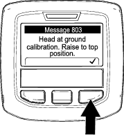
Running the Teach Ground Height Application
-
Rotate the ignition key to the RUN position.
Note: The TRANSPORT mode screen or the AERATE mode screen displays (Figure 65).
-
Move the handlebar so that you can see the outermost tines you positioned in Preparing the Machine.
-
Press the right InfoCenter button until the TEACH GROUND HEIGHT wizard displays.
-
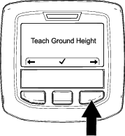
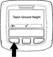
On the Teach Ground Height screen (Figure 66), press the center InfoCenter button.
-
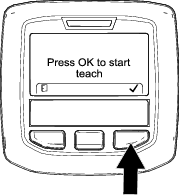
On the Press OK to Start Teach screen (Figure 67), press the right InfoCenter button.
Note: The CALIBRATION ENGAGED message displays (Figure 68), and the coring head slowly lowers.
Important: Keep your hand near the InfoCenter.
Note: The coring head lowers slower if the hydraulic fluid is cold.

-
When any tine touches the ground, press the right InfoCenter button on the Lowering Head screen (Figure 69).
Note: Tines should only touch the ground, and not lift or unload the weight from the tires.If the coring head lifts the machine, the machine incorrectly calibrates the ground height, resulting in inaccurate hole depth and entry tufting of the aeration hole.

Note: the CALIBRATION COMPLETE message displays (Figure 70), and the head fully raises.

-
Press the left InfoCenter button to exit the Teach Ground Height application (Figure 71).
During Operation
During Operation Safety
-
The owner/operator can prevent and is responsible for accidents that may cause personal injury or property damage.
-
Wear appropriate clothing, including eye protection; long pants; substantial, slip-resistant footwear; and hearing protection. Tie back long hair, secure loose clothing, and do not wear loose jewelry.
-
Do not operate the machine when tired, ill, or under the influence of alcohol or drugs.
-
Keep bystanders, children, and pets out of the operating area. Do not allow children to operate the machine. Allow only people who are responsible, trained, familiar with the instructions, and physically capable to operate the machine.
-
Never carry passengers on the machine.
-
Operate the machine only in good visibility to avoid holes or hidden hazards.
-
Keep your hands and feet away from the tines.
-
Look behind and down before backing up to be sure of a clear path.
-
Stop the machine, shut off the engine, remove the key, wait for all moving parts to stop, and inspect the tines after striking an object or if there is an abnormal vibration in the machine. Make all necessary repairs before resuming operation.
-
Always maintain proper tire pressure.
-
Reduce traction speed on rough roads and surfaces.
Slope Safety
-
Slopes are a major factor related to loss of control and rollover accidents, which can result in severe injury or death. You are responsible for safe slope operation. Operating the machine on any slope requires extra caution.
-
Evaluate the site conditions to determine if the slope is safe for machine operation, including surveying the site. Always use common sense and good judgment when performing this survey.
-
Review the slope instructions listed below for operating the machine on slopes and review the conditions to determine whether you can operate the machine in the conditions on that day and at that site. Changes in the terrain can result in a change in slope operation for the machine.
-
Avoid starting, stopping, or turning the machine on slopes. Avoid making sudden changes in speed or direction. Make turns slowly and gradually.
-
Do not operate a machine under any conditions where traction, steering, or stability is in question.
-
Remove or mark obstructions such as ditches, holes, ruts, bumps, rocks, or other hidden hazards. Tall grass can hide obstructions. Uneven terrain could overturn the machine.
-
Be aware that operating the machine on wet grass, across slopes, or downhill may cause the machine to lose traction. Loss of traction to the drive wheels may result in sliding and a loss of braking and steering.
-
Use extreme caution when operating the machine near drop-offs, ditches, embankments, water hazards, or other hazards. The machine could suddenly roll over if a wheel goes over the edge or the edge caves in. Establish a safety area between the machine and any hazard.
Engaging Parking Brake
-
Fully raise the handlebar to engage the parking brake (Figure 72).
-
Ensure that the handlebar-latch pin extends through the hole in the detent plate (Figure 73).
Warning
If the parking brake does not engage, the machine may move injuring you or bystanders.
Ensure that the handlebar is fully raised and securely latches to the detent plate.
Releasing the Parking Brake
Starting the Engine
-
Fully raise and latch the handlebar engage the parking brake; refer to Engaging Parking Brake.
-
Use the choke (Figure 77) as follows:
-
Before starting a cold engine, move the choke control to the ON position.
-
When starting a warm or hot engine, you may not need to use the choke.
-
-
Move the throttle lever to the FAST position before starting a cold engine.
-
Turn the ignition key to the START position. When the engine starts, release the key.
Important: Do not engage the starter for more than 10 seconds at a time. If the engine fails to start, allow a 30-second cool-down period between attempts. Failure to follow these instructions can burn out the starter motor.
-
After the engine starts, move the choke toward the OFF position. If the engine runs rough or stalls, move the choke back toward the ON position for a few seconds. Then move the throttle lever to desired engine speed.
Note: Repeat this step as required.
Shutting Off the Engine
Caution
Children or bystanders may be injured if they move or attempt to operate the machine while it is unattended.
Always fully raise and latch the handlebar to engage the parking brake, shut off the engine, and remove the key when leaving the machine unattended, even if just for a few minutes.
-
Fully raise and latch the handlebar to engage the parking brake; refer to Engaging Parking Brake.
-
Move the throttle lever (Figure 78) to the SLOW position.
-
Let the engine idle for 60 seconds.
-
Turn the ignition key to the OFF position and remove the key.
-
If you are hauling or storing the machine, close the fuel-shutoff valve (Figure 79).
Important: Close the fuel-shutoff valve before hauling the machine on a trailer or storing the machine. Fully raise and latch the handlebar to engage the parking brake before hauling the machine. Remove the key from the ignition switch to prevent the fuel pump from running and causing the battery to discharge.
Using the Machine
Important: Walk in front of the machine in a forward direction while operating it, do not walk and face rearward when operating the machine.
Speed Lock
Speed Lock in the Transport Mode
Using the Speed Lock allows you to drive the machine without having to hold the traction control.
Note: You cannot use the speed lock feature while driving the machine backward.
Speed Lock in the Aerate Mode
Using the speed lock while aerating allows you to continue driving the machine at the selected hole-spacing speed at the end of an aeration pass, turn the machine around, and begin the next aeration pass without changing the traction control position.
Note: The speed lock feature in the aerate mode is active when the coring head is set for delay-drop mode; the speed lock feature is locked-out in the immediate-drop mode.
Using the Ground-Speed Lock
Transport Mode
The ground-speed lock operates like automotive cruise control.
-
Press the transport/aerate switch to the TRANSPORT position (Figure 81).
-
Press the speed-lock switch to the ON position.
-
Drive the machine forward at the desired ground speed.
-
Press the speed-lock switch to the ENGAGE position.
Note: The ground-speed lock maintains the current ground speed at which the machine is driving. You can release the traction control.
-
To disengage the speed lock operation, perform one of the following:
-
Press the speed-lock switch to the OFF position.
-
Rotate the top of the traction control rearward to drive the machine backward.
-
Release the operator presence bail.
-
Press the bump-stop switch.
-
Using the Ground-Speed Lock
Aerate Mode
Note: The ground-speed lock is not available when aerating in the immediate-drop mode.
-
Press the transport/aerate switch is in the AERATE position (Figure 82).
-
Press the speed-lock switch to the ON position.
-
Drive the machine forward and close the aerate bail.
Note: The ground-speed lock engages, and the coring head lowers.
-
At the end of the aeration pass, release the aerate bail.
Note: The coring head raises, but the machine maintains ground speed at the aeration hole spacing rate.
-
To disengage the speed lock operation, perform one of the following:
-
Press the speed-lock switch to the OFF position.
-
Rotate the top of the traction control rearward to drive the machine backward.
-
Release the operator presence bail.
-
Press the bump-stop switch.
-
Driving the Machine in the Transport Mode
Note: Use the transport mode when you move the machine between job sites.
Note: The machine drives at a reduced variable speed anytime the transport/aeration switch is in the AERATION position.
-
Start the engine, and move the throttle control to the FAST position; refer to Starting the Engine.
-
Lower the handlebar to release the parking brake; refer to Releasing the Parking Brake.
-
Press the left side of the transport/aeration switch to the TRANSPORT position (Figure 83).
Note: The InfoCenter displays the TRANSPORT icon (Figure 84).
-
Look in the direction of your planned path to ensure that it is clear.
-
Grasp the left or right handlebar and the operator-presence bail (Figure 83), and squeeze the bail to the handle.
-
With you thumb, rotate the left or right traction control to drive the machine as follows:
-
Rotate the top of the traction control forward to drive the machine forward.
-
Rotate the top of the traction control rearward to drive the machine backward.
Note: Further rotating the traction control increases the groundspeed of the machine.
-
Stopping the Machine
Important: To immediately stop the machine press the bump-stop switch (Figure 85).
-
If you are aerating, release the aerate bail (Figure 86) to raise the coring head; refer to Raising the Coring Head.
-
Release the traction control, and allow it to move to the NEUTRAL position.
-
Release the operator-presence bail.
-
Fully raise and latch the handlebar to engage the parking brake; refer to Engaging Parking Brake.
Driving the Machine in the Aerating Mode
Note: The machine drives at a reduced variable speed anytime the coring head is raised.
-
Start the engine, and move the throttle control to the FAST position; refer to Starting the Engine.
-
Lower the handlebar to release the parking brake; refer to Releasing the Parking Brake.
-
Press the right side of the transport/aeration switch to the AERATE position (Figure 87).
The InfoCenter displays the current hole depth and hole spacing (Figure 88).

-
Look in the direction of your planned path to ensure that it is clear.
-
Grasp the left or right handlebar and the operator-presence bail (Figure 87), and squeeze the bail to the handle.
-
With you thumb, rotate the top of the left or right traction control to drive the machine forward.
Note: During aeration the machine drives at a speed to meet what you selected for target hole spacing.
-
When using the ground-speed lock, releasing the aerate bail without changing the traction control position causes the machine to maintain ground speed, like cruise control of an automobile.
-
Driving the machine in reverse direction disengages the cruise control effect, and causes the machine to drive at variable-ground speed.
-
When you raise the head to turn the machine around for another pass, you can increase ground speed by moving the traction control farther forward. When you return the traction control to the NEUTRAL position, the machine slows to the required ground speed for aeration hole spacing.
-
Aerating Using the Delay-Drop Mode
Use the front tire to sight the drop point when aerating in delay-drop mode.
-
Press the top of the drop-control switch (Figure 89) to the DROP-DELAY position.
-
Drive the machine in the forward direction; refer to Driving the Machine in the Aerating Mode.
-
As the front tire rolls over the perimeter of aeration area, close either the left or right the aerate bail (Figure 90).
Note: The coring head runs and lowers as the machine moves forward crossing the target aeration area.
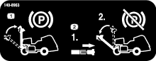
Raising the Coring Head
Delay-Drop Mode
Use the front tire (Figure 91) to sight the raise point when in delay-drop mode.
To raise the core head, perform 1 of the following:
-
As the front tire rolls over the perimeter of aeration area, release the aerate bail (Figure 92).
Note: The machine delays lifting the coring head until the coring head reaches the targeted spot you identified using the front tire and released the aerate bail.
-
Drive the machine in the reverse direction; refer to Driving the Machine in the Reverse Direction.
Aerating Using the Immediate-Drop Mode
-
Press the bottom of the drop-control switch (Figure 93) to the IMMEDIATE-DROP position.
Note: The light in the switch illuminates.
-
Drive the machine in the forward direction; refer to Driving the Machine in the Aerating Mode.
-
Close either the left or right the aerate bail (Figure 94).
Note: The coring head immediately lowers and begins aerating.
Raising the Coring Head
Immediate-Drop Mode
To raise the core head, perform 1 of the following:
-
Release the aerate bail (Figure 95).
Note: The machine lifts the coring head immediately.
-
Drive the machine in the reverse direction; refer to Driving the Machine in the Reverse Direction.
Driving the Machine in the Reverse Direction
Resetting the Bump-Stop Switch
-
Release the traction control and allow it to move to the NEUTRAL position, and release the operator-presence bail (Figure 98).

-
Move away from the bump-stop switch (Figure 99).
Note: A spring in the bump-stop switch resets the switch.
-
Grasp the left or right handlebar and the operator-presence bail (Figure 100), and squeeze the bail to the handle.
-
Drive the machine, refer to Driving the Machine in the Transport Mode or Driving the Machine in the Aerating Mode.
Using the Line Marker
Use the line marker to align aeration rows (Figure 101).
Using Aerator Statistics for Estimating Topdressing
The machine uses 2 counters to log the area aerated and the displaced soil-core volume. Use the information from these counters to estimate the amount of top dressing to apply to the aerated turf area(s).
-
The Area 1 counter is not PIN code protected, and is intended to be reset by the machine operator.
Note: If the operator records the Area 1 counter for each aeration site, you can estimate the amount of topsoil and delivery requirements for each site.
-
The Area 2 counter is PIN code protected, and is intended to be reset by the supervisor or their delegate.
-
The area aerated displays in m2 (SI) or ft2 (English) units of measure.
-
The displaced-coring volume displays as m3 (SI) or yd3 (English) units of measure.
-
When viewing the displaced-coring volume counters, the machine calculates the volume using the tine diameter and the tine quantity that you entered in the InfoCenter.
Important: If the tine diameter and/or the tine quantity value(s) are incorrect before aerating the site, the InfoCenter will calculate and display incorrect core volume values for Area 1 and Area 2. If the diameter and/or quantity values are changed after aerating, the InfoCenter will change the displayed volume values.
Accessing the Area and Volume Counters
-
Park the machine on a level surface.
Note: The handlebar remain lowered so that you can view the InfoCenter.
-
Ensure that the engine is running or the ignition key in the RUN position.
-
In the InfoCenter, navigate to the MAIN MENU (Figure 103).

-
Press the center InfoCenter button until the SERVICE option is selected, and press the right button.
-
In the SERVICE screen, press the center InfoCenter button until the STATISTICS option is selected, and press the right button (Figure 104).
Note: An AREA counter displays in the STATISTICS screen.
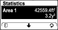
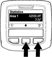
Using the Area 1—Area and Volume Counters
Machine Operator
-
In the STATISTICS screen, press the center InfoCenter button until the AREA 1 option is selected (Figure 106).
-
Record the aeration area and soil-core volume in a worksheet; refer to the example that follows.
Example Aeration Worksheet
Date
Course (if multiple)
Location
Aeration Area
Core Volume
-
Press the right button to display to the reset area and volume screen.
-
In the RESET AREA AND VOLUME SCREEN, press the right InfoCenter button.
Note: The InfoCenter displays the statistic screen, and the area and volume counters reset to 0.
Note: If you do not reset the Area 1 counter, the area and volume counters continue to accumulate data.

-
Repeat steps 1 through 4 as needed.
-
Press the left InfoCenter button until the RUN screen appears.
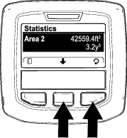
Resetting the Area 2—Area and Volume Counters
Supervisor
Note: Resetting the AREA 2 counters does not reset the AREA 1 counters.
-
Enter the PIN code for the PROTECTED MENUS option (Figure 108), refer to Accessing Protected Menus.

-
Enter the PIN to access protected menus; refer to Accessing Protected Menus.
-
In the STATISTICS screen, press the center InfoCenter button until the AREA 2 option is selected (Figure 109).
-
If needed, record the aeration area and soil-core volume data.
-
Press the right button to display to the reset area and volume screen.
-
In the RESET AREA AND VOLUME SCREEN, press the right InfoCenter button (Figure 110).
Note: The InfoCenter displays the statistic screen, and the area and volume counters reset to 0.
Note: If you do not reset the Area 2 counter, the area and volume counters continue to accumulate data.
-
Press the left InfoCenter button until the RUN screen appears.
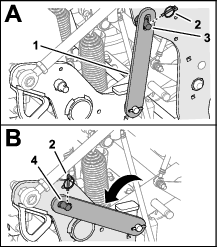
Supporting the Coring Head with the Service Latch
Install the service latch before performing coring head maintenance or when storing the machine for more than a couple of days.
Danger
If the coring head is raised and not latched, it can lower unexpectedly and injure you or bystanders.
Any time you service the coring head, including changing of tines or turf guards, use the service latch to secure coring head in the raised position.
-
Raise the coring head.
-
Park the machine on a level surface, fully raise and latch and latch the handlebar to engage the parking brake, shut off the engine, remove the key, and wait for all moving parts to stop.
-
Remove the coring head cover; refer to Removing the Coring-Head Cover.
-
Remove the lynch pin securing the service latch to the side plate (Figure 111).
-
Rotate the service latch rearward and align it over the support pin of the coring head.
-
Secure the latch to the support pin with the lynch pin.
-
If needed, install the coring-head cover; refer to Installing the Coring-Head Cover.
Stowing the Service Latch
-
Park the machine on a level surface, fully raise and latch and latch the handlebar to engage the parking brake, shut off the engine, remove the key, and wait for all moving parts to stop.
-
If the coring-head cover is installed, remove it; refer toRemoving the Coring-Head Cover.
-
Remove the lynch pin securing the service latch to the support pin of the coring head (Figure 112).
-
Rotate the service latch down and align it over the support pin of the side plate.
-
Secure the latch to the support pin with the lynch pin.
-
Install the coring-head cover; refer to Installing the Coring-Head Cover.
Replacing a Damaged Tine
Important: Replacing a damaged tine with one that is the same length. Different tine lengths negatively affect hole appearance.
Different tine lengths affect hole appearance.
Refer to Installing Turf Guards, Tine Holders, and Tines for illustrations.
-
Raise the coring head and lock it in position with the service latch.
-
Park the machine on a level surface, fully raise and latch the handlebar to engage the parking brake, shut off the engine, remove the key, and wait for all moving parts to stop.
-
Loosen the tine holder bolts and remove the old tine(s).
-
Insert the new tine(s) into the tine holder.
-
Torque the tine holder bolts to 40.6 N∙m (30 ft-lb).
-
If needed, repeat this procedure on the remaining arms.
Checking the Tine Ground-Height Calibration
Use the ground height calibration recall application to quickly check the current tine ground height.
Preparing the Machine
-
Ensure that the coring head is raised.
-
Park the machine on a level surface, fully raise and latch the handlebar to engage the parking brake, shut off the engine, remove the key, and wait for all moving parts to stop.
-
Remove the coring-head cover; refer to Removing the Coring-Head Cover.
-
Rotate coring-head pulley (Figure 113) until the outermost tines are aligned closest to the ground.
Important: Keep your fingers away of the area where the belt merges and departs the pulley so that you do not pinch your fingers.
-
Install the coring-head cover; refer to Installing the Coring-Head Cover.
Running the Recall Ground Height Application
-
Press the center button on the InfoCenter to navigate to the RECALL GROUND HEIGHT option.
-
Press the right InfoCenter button to select the TEACH GROUND HEIGHT option.
-
On the Recall Ground Height screen (Figure 114), press the center InfoCenter button.

-
On the Head Will Lower screen (Figure 115), press the right InfoCenter button.

Note: The Lowering Head message displays and the coring head lowers.

-
Watch the outermost tines for the following out-of-calibration conditions.
-
The tines begin to penetrate the ground—press the right InfoCenter button (Figure 117) and run the Teach Ground Height application; refer toRunning the Teach Ground Height Application.
-
The tines are above the ground—press the right InfoCenter button and run the Teach Ground Height application; refer to Running the Teach Ground Height Application.
-
-
If the outermost tines lightly touch the ground, press the right InfoCenter button to raise the coring head.
Adjusting the Weight Transfer
The machine transfers weight from the traction unit to the coring head to help maintain hole depth in various soil structures. However, if the soil structure is firm enough to not allow full aeration depth, the coring head may need additional weight transfer. The machine is set for normal weight transfer at the factory. To increase the down pressure of the weight transfer springs, proceed as follows:
Warning
Sudden release of the spring plates could cause injury.
Acquire the help of another person to help adjust the weight transfer spring.
-
Park the machine on a level surface, fully raise and latch the handlebar to engage the parking brake, shut off the engine, remove the key, and wait for all moving parts to stop.
-
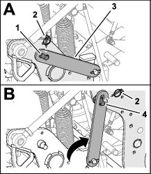
Loosen the forward flange locknut and carriage bolt that secure the spring-tension plate to the support bracket of the coring head (Figure 118).
Note: Do not remove locknut and carriage bolt.
-
Remove the rear flange locknut that secures the spring brackets to the support bracket.
Note: Do not remove carriage bolt.
-
Insert a 1/2 inch-drive ratchet or breaker bar into the square hole in the spring-tension plate (Figure 119).
-
Rotate the ratchet or breaker bar to relieve the tension on the rear carriage bolt and remove it from the upper hole.
Note: The upper hole is the normal weight transfer position.
-
Rotate the spring-tension plate until it aligns with the lower hole in the support bracket, insert the carriage bolt through the holes in the plate and bracket.
Note: The lower hole is the higher weight transfer position. Rotating the spring plates upward increases the weight transfer.
-
Secure the carriage bolt to the support bracket and spring-tension plate with the flange locknut.
-
Torque the locknuts to 37 to 45 N∙m (27 to 33 ft-lb).
Using Manual Ground Following
For optimum hole quality and machine performance, aerate using the automatic ground following system.
Use manual ground following only if the tine-position sensor is damaged.
Adjusting the Depth-Stop Spacers
-
Park the machine on a level surface, fully raise and latch the handlebar to engage the parking brake, shut off the engine, remove the key, and wait for all moving parts to stop.
-
Remove the coring-head cover; refer to Removing the Coring-Head Cover.
-
Remove the lynch pin that secures the depth-stop pin and spacers to the stop bracket (Figure 120 and Figure 121).
-
Position the spacers above or below the stop bracket to adjust the coring depth.
-
With all spacers at the top of the stop bracket, the depth setting is 10.7 cm (4-1/4 inches).
-
Thick spacers equate to 19 mm (3/4 inch) increment.
-
Thin spacer equates to 9.5 mm (3/8 inch) depth increment.
Note: You must install all spacers, regardless of their position.
-
-
Assemble the depth-stop pin and the spacers to the stop bracket with the lynch pin.
-
Repeat steps 3 through 5 at the other side of the machine.
Important: Ensure that the spacer location above and below the left and right stop brackets are identical.
-
Install the coring-head cover; refer to Installing the Coring-Head Cover.
Setting the InfoCenter
Note: If you aerate in manual mode, you must set the InfoCenter for the manual ground following mode each time you start the engine.
-
Turn the ignition key to RUN position.
Note: Do not start the engine.
-
In the InfoCenter, navigate to the MAIN MENU (Figure 122).

-
Press the center InfoCenter button until the SETTING option is selected, and press the right button.
-
Press the center InfoCenter button until the PROTECTED MENUS option is selected (Figure 123), press the right button, and enter your 4-digit pin code (e.g. 1 2 3 4).
-
Press the center InfoCenter button until the MANUAL AERATION option is selected, and press the right button (Figure 124) to set manual aeration to ON.

-
Start the engine.
-
Aerate using Aerating Using the Delay-Drop Mode or the Aerating Using the Immediate-Drop Mode.
Note: When you shut off the engine and start it, the machine defaults to the automatic ground-following mode.
Stowing the Depth-Stop Spacers for Automatic Ground Following
-
Park the machine on a level surface, fully raise and latch the handlebar to engage the parking brake, shut off the engine, remove the key, and wait for all moving parts to stop.
-
Remove the coring-head cover; refer to Removing the Coring-Head Cover.
-
Remove the lynch pin that secures the depth-stop pin and spacers to the stop bracket (Figure 125).
-
Position the all the spacers above the stop bracket.
-
Assemble the depth-stop pin and the spacers to the stop bracket with the lynch pin.
Note: You must stow all spacers.
-
Repeat steps 3 through 5 at the other side of the machine.
-
Install the coring-head cover; refer to Installing the Coring-Head Cover.
Adding Additional Weight
With the weight transfer adjusted, it is possible to aerate turf that is hard enough ground cause the machine to lift the rear tires off the ground. This may lead to irregular hole spacing.
If this lifting occurs, you can add optional counterweight plates to the rear frame axle tube. Each counterweight plate adds 28.5 kg (63 lb) to the machine. You can add up to 2 plates. Refer to the Parts Catalog of your machine for the counterweight and hardware part numbers.
Moving the Machine by Hand
Bypassing the Hydraulic Pump and Moving the Machine
Required tools: 15 mm socket and socket wrench
Important: Do not operate the engine with the bypass valve open for more than 10 to 15 seconds.
-
If possible, park the machine on a level surface.
-
Fully raise and latch the handlebar to engage the parking brake, shut off the engine, remove the key, and wait for all moving parts to stop.
-
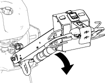
Remove the 2 flange head bolts that secure the storage bin to the bin bracket (Figure 126).
-
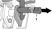
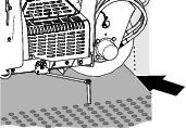
Locate the cover for the bypass-valve screw between the engine and hydraulic pump as shown in Figure 127).
-
Use a 15 mm socket and socket wrench to rotate the bypass valve counterclockwise 1-1/2 turns.
Important: Do not rotate the bypass valve more than 1-1/2 turns.
-
If you tow the machine, pull it using the front tie-down hoop (Figure 128).
Important: Do not push/pull the machine more than 30.5 m (100 ft) or faster than 0.6 km/h (1 mph) because hydraulic component damage may occur.
-
Lower the handlebar to disengage the parking brake before pushing/pulling the machine.
Important: You must lower the handlebar to disengage the parking brake before you move the machine.
Restoring the Hydraulic Pump
Important: You must close the bypass valve to drive the machine. Do not try to operate traction system with the bypass valve open.
-
Locate the bypass-valve screw between the engine and hydraulic pump.
Note: The location of the cover for the bypass-valve screw is shown in Figure 129.
-
Use a 15 mm socket and socket wrench to rotate the bypass valve clockwise 1-1/2 turns.
Note: Do not overtighten the bypass screw.
-
Use a 15 mm wrench to install the bypass-screw cover onto the hydraulic pump.
-
Install the storage bin to the bin bracket with the 2 flange-head bolts.
Moving the Machine when the Coring Head is Lowered
If the engine stops running while the coring head lowered and the tines engaged in the soil and you cannot start the engine, perform either Lifting the Coring Head using the Starter or Removing the Tine holders from the Stomper Arms.
Lifting the Coring Head using the Starter
-
Move the key to the RUN position.
-
In the InfoCenter, navigate to the MAIN MENU (Figure 130).
-
Press the center InfoCenter button until the SETTINGS option is selected, and press the right button.
-
Press the center InfoCenter button until the SERVICE LIFT option is selected (Figure 131), press the right button.
Note: The service lift option changes to YES.
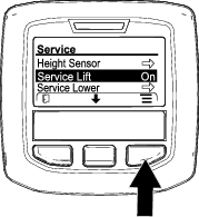
-
Move the key to the START position, and crank the starter for 10 seconds.
Important: Do not engage the starter for more than 10 seconds at a time. If the tines have not cleared the ground, allow a 30-second cool-down period between attempts. Failure to follow these instructions can burn out the starter motor.
Note: The coring head lifts the tines from the ground.
Important: The tines fully clear the ground before moving the machine.
-
Open the bypass valve; refer to Bypassing the Hydraulic Pump and Moving the Machine.
-
Pull/push the machine to a nearby location to continue service or load onto a trailer.
Important: Do not pull/push machine for more than 30.5 m (100 ft) and no faster than 1.6 km/h (1 mph), because hydraulic damage may occur.
Removing the Tine holders from the Stomper Arms
-
Remove the tine holders from the stomper arms.
-
Open the bypass valve; refer to Bypassing the Hydraulic Pump and Moving the Machine.
-
Pull/push the machine to a nearby location to continue service or load onto a trailer.
Important: Do not pull/push machine for more than 30.5 m (100 ft) and no faster than 1.6 km/h (1 mph), because hydraulic damage may occur.
Operating Tips
General
Warning
Contacting obstacles with the machine may cause you to lose control of it.
Always be aware of obstacles at the job site. Plan your aeration path to avoid contact with any obstacle by you or the machine.
-
Make very gradual turns when aerating. Never make sharp turns with the coring head engaged. Plan your aeration path before lowering the aerator.
-
Always maintain awareness of what lies ahead in the direction of forward travel. Avoid aeration next to buildings, fences, and other equipment.
-
Look behind frequently to ensure that the machine operates properly, and you maintain alignment with previous pass.
-
Always clear the area of all damaged machine parts, such as broken tines, etc., to prevent their being picked up by mowers or other turf maintenance equipment.
-
Replace broken tines and inspect and correct damage to those still usable. Repair any other machine damage before commencing operation.
-
When aerating with less than the full width of the machine, you may remove tines, but the tine heads should remain installed on the stomper arms to ensure proper balance and operation of the machine.
-
This machine aerates deeper than most greens aerators. On native or modified push-up greens and tees, the deeper depth and longer hollow tines may have difficulty ejecting the complete core. This is due to harder native soil that sticks in the end of the tine. Side-eject greens/tees tines from the manufacturer stay cleaner and reduce the time required to clean the tines out. You will eventually eliminate this condition with continued aeration and top-dressing programs.
Hard Ground
If the ground is too firm to obtain the desired coring depth, the coring head can get into a bouncing rhythm. This is due to the hard pan the tines are attempting to penetrate. Correct this condition by attempting the following:
-
Do not aerate if ground is too hard or dry. You obtain best aeration results after a rain or watering the turf the previous day.
-
Change to a 3-tine head, if attempting to use the 4-tine head or reduce the number of tines per stomper arm. Attempt to maintain a symmetrical tine configuration to evenly load the stomper arms.
-
If ground is hard packed, reduce aerator penetration (depth setting), clean up the cores, water the turf, and re-aerate at a deeper penetration.
Aeration of soil types built on top of hard subsoils (i.e., soil/sand placed over rocky soil) can cause undesired hole quality. This occurs when the aeration depth is greater than the built up soil and the subsoil is too hard to penetrate. When the tines contact this harder subsoil, the aerator may lift and cause the top of the holes to become elongated. Reduce the aerating depth sufficiently to avoid penetration into the hard subsoil.
Entrance Hole Quality
The entrance hole quality is deteriorating when the hole is slotted (pulled forward).
If the hole entrance quality is deteriorating, check the tine ground-height calibration, refer to Checking the Tine Ground-Height Calibration.
Mini Tine (Quad Tine)
Because of the double row design, the mini-tine coring head requires the hole spacing to be set at 6.3 cm (2-1/2 inches). Ground speed is critical to maintain the appearance of 3.2 cm (1-1/4 inches) hole spacing. Refer to Setting the Hole Spacing if your hole spacing requires a small change.
With the mini tine head or larger solid tine use, the turf root structure is important to preventing turf damage due to tearing of the root zone. If the center 2 arms begin to lift the turf or damage to the root zone is excessive, proceed as follows:
-
Increase the hole spacing
-
Decrease tine size
-
Decrease tine depth
-
Remove some of the tines
The lifting action that solid a tine creates when it pulls from the turf may cause turf damage. This lift can tear the root zone if the density of tines or diameter of tines is too high.
Front Hole Dimple or Push During the Aeration Pass (Solid Tines or Softer Soil Conditions)
When aerating with longer solid tines (i.e., 3/8 x 4 inches long) or needle type tines, the front of the holes may become slotted or tufted. To regain excellent hole quality for this configuration, try the following:
-
Calibrate the tine ground height; refer to Calibrating the Tine Ground Height.
-
Slow the engine high idle speed down to 2800 to 2900 rpm.
Note: Because traction and coring head speeds increase and decrease together with engine speed, hole spacing is not affected.
If slowing the engine speed does improve hole quality for the longer solid or needle type tines, adjust the roto-link damper.
Note: Under most conditions, the factory setting works best.
-
If the front of the holes is slotted or tufted, a stiffer roto-link setting helps resist hole-push and improve hole quality.
-
If the back of the holes is slotted or tufted, a softer roto-link setting helps improve the hole quality.
Note: You must reverse the position of the roto-Link damper if you change back to a coring style tine or any of the mini-tines.
Preparing the Machine
-
Park the machine on a level surface, fully raise and latch the handlebar to engage the parking brake, shut off the engine, remove the key, and wait for all moving parts to stop.
-
Remove the coring-head cover; refer to Removing the Coring-Head Cover.
-
Secure the coring head with the service latch; refer to Supporting the Coring Head with the Service Latch.
Adjusting the Roto-Link Dampeners
Note: The factory positions 1 roto-link spacer at the roto-link dampener shaft and 1 spacer is in the stowed position for each stomper arm.
Note: Adjusting the roto-link dampers allows you to operate the machine at full engine speed (3400 rpm), however you may need to aerate at slower engine speeds to improve the hole quality.
-
Remove the 2 flange locknuts that secure the roto-link dampener shaft to the rear frame of the machine (Figure 132).
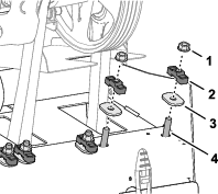
-
Remove the spacer (if stowed) and hardened oval washers.
-
Rotate the dampener link and dampener shaft down (Figure 133).
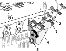
-
Position the roto-link spacer to correct the following hole-mounding conditions:
Note: Each spacer is equivalent to 12.7 mm (1/2 inch). The lower bumper-spacer must remain assembled to the damper shaft.
-
If the front of the holes is slotted or tufted—position the spacers above the rear frame, in the stowed position.
-
If the back of the holes is slotted or tufted—position both spacers above the rear frame, at each side of the roto-link dampener shaft.
-
-
Rotate the dampener link and dampener shaft up, and insert the studs through the holes in the rear frame of the machine.
-
Secure the dampener shaft and spacers to the rear frame with the hardened oval washers and locknuts (Figure 134).
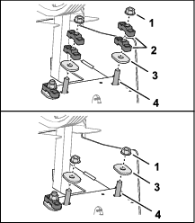
-
Torque the flange locknuts to 47 to 61 N∙m (35 to 45 ft-lb).
-
Repeat steps 1 through 7 at the next 2 stomper arms.
Installing the Coring-Head Cover
-
Stow the service latch; refer to Stowing the Service Latch.
-
Install the coring-head cover; refer to Installing the Coring-Head Cover.
Calibrating Ground Height
Perform the calibrating the tine ground height procedure; refer to Calibrating the Tine Ground Height.
Testing Hole Quality
-
Take the machine to a test area, and aerate the turf to compare the hole quality.
-
If hole quality improved, repeat the steps in Preparing the Machine, Adjusting the Roto-Link Dampeners, and Installing the Coring-Head Cover to adjust the roto-link dampener at the other 3 stomper arms.
After Operation
After Operation Safety
-
Park the machine on a level surface, fully raise and latch the handlebar to engage the parking brake, shut off the engine, remove the key, and wait for all moving parts to stop.
-
Lower the coring head or secure it with the service latch when you are not running the machine.
-
Keep all parts of the machine in good working condition and all hardware tightened.
-
Replace all worn, damaged, or missing decals.
Cleaning the Machine
| Maintenance Service Interval | Maintenance Procedure |
|---|---|
| Before each use or daily |
|
Important: Do not use brackish or reclaimed water to clean the machine.
Important: Do not pressure wash the machine.
-
Park the machine on a level surface, fully raise and latch the handlebar to engage the parking brake, shut off the engine, remove the key, and wait for all moving parts to stop.
-
Thoroughly wash the machine.
-
Use a garden hose without a nozzle to avoid forcing water past the seals and contaminating bearing grease.
-
Use a brush to remove caked-on material.
-
Use mild detergent to clean the covers.
-
-
After cleaning, apply a coat of auto wax periodically to maintain the glossy finish of the cover.
-
Inspect the machine for damage, oil leaks, and component and tine wear.
-
Remove, clean, and oil the tines. Spray a light oil mist on coring head bearings (crank and damper links).
Important: Secure the coring head with the service latch if you store the machine for more than a couple of days.
Tie-Down Points
There are tie-down hoops located at the front and rear sides of the machine (Figure 135, Figure 136, and Figure 137).
Note: Use properly-rated DOT-approved straps to tie down the machine; refer to Specifications for the weight of the machine.
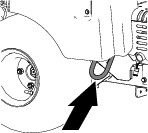
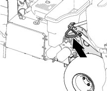
Hauling the Machine
Warning
Driving the machine on street or roadway without turn signals, lights, reflective markings, or a slow-moving vehicle emblem is dangerous and can lead to accidents causing personal injury.
Do not operate the machine on a public street or roadway.
Important: Use full-width ramps for loading the machine onto a trailer or truck.
-
Load the machine onto the trailer or truck (coring head forward—preferred).
-
Fully raise and latch the handlebar to engage the parking brake, shut off the engine, remove the key, and wait for all moving parts to stop.
-
Secure the coring head with the service latch; refer to Supporting the Coring Head with the Service Latch.
-
Close the fuel-shutoff valve; refer to Fuel-Shutoff Valve.
-
At the tie-down points, bind the machine to the trailer or truck with cables, chains, or straps; refer to Tie-Down Points
| Weight | 745 kg (1,642 lb) or 829 kg (1,827 lb) with 2 optional weights |
| Width | 130 cm (51 inches) minimum |
| Length | 267 cm (105 inches) minimum |
| Ramp Angle | 3.5/12 pitch (16°) maximum |
| Load Direction | Coring head forward (preferred) |
| Vehicle Tow Capacity | Greater than gross trailer weight (GTW) |
Maintenance
Note: Download a free copy of the electrical or hydraulic schematic by visiting www.Toro.com and searching for your machine from the Manuals link on the home page.
Note: Refer to your engine owner’s manual for additional maintenance procedures.
Note: Determine the left and right sides of the machine from the normal operating position.
Maintenance Safety
-
Park the machine on a level surface, fully raise and latch the handlebar to engage the parking brake, shut off the engine, remove the key, and wait for all moving parts to stop. Allow the machine to cool before adjusting, servicing, cleaning, or storing it.
-
Perform only those maintenance instructions described in this manual. If the machine needs major repair or you need assistance, contact an authorized Toro distributor.
-
Ensure that the machine is in safe operating condition by keeping nuts, bolts, and screws tight.
-
If possible, do not perform maintenance while the engine is running. Keep away from moving parts.
-
Carefully release pressure from components with stored energy.
-
Check the tine mounting bolts daily to be sure that they are tightened to specification.
-
Ensure that all guards are installed, and the hood is secured shut after maintaining or adjusting the machine.
Recommended Maintenance Schedule(s)
| Maintenance Service Interval | Maintenance Procedure |
|---|---|
| After the first 8 hours |
|
| After the first 50 hours |
|
| Before each use or daily |
|
| Every 25 hours |
|
| Every 50 hours |
|
| Every 100 hours |
|
| Every 200 hours |
|
| Every 400 hours |
|
| Every 500 hours |
|
| Before storage |
|
| Yearly |
|
Important: Refer to your engine owner’s manual for additional maintenance procedures.
Pre-Maintenance Procedures
Caution
If you leave the key in the ignition switch, someone could accidently start the engine and seriously injure you or other bystanders.
Park the machine on a level surface, fully raise and latch the handlebar to engage the parking brake, shut off the engine, remove the key, and wait for all moving parts to stop.
Important: The fasteners on the covers of this machine are designed to remain on the cover after removal. Loosen all the fasteners on each cover a few turns so that the cover is loose but still attached, then go back and loosen them until the cover comes free. This prevents you from accidentally stripping the bolts free of the retainers.
Preparing the Machine for Maintenance
-
Park the machine on a level surface.
-
Fully raise and latch the handlebar to engage the parking brake; refer to Engaging Parking Brake.
-
Shut off the engine, remove the key, and wait for all movement to stop before leaving the machine; refer to Shutting Off the Engine.
-
Allow the machine to cool.
Lifting the Machine
Caution
If the machine is not properly supported by blocks or jack stands, the machine may move or fall, which may result in personal injury.
-
When changing attachments, tires, or performing other service, use the correct blocks, hoists, and jacks.
-
Make sure that the machine is parked on a solid, level surface such as a concrete floor.
-
Prior to raising the machine, remove any attachments that may interfere with the safe and proper raising of the machine.
-
Always chock or block wheels. Use jack stands or solid wood blocks to support the raised machine.
Jacking the Front End
-
Prepare the machine for maintenance; refer to Preparing the Machine for Maintenance.
-
Chock the rear tires to prevent the machine from moving.
Important: To prevent wheel motor damage, do not use the front wheel motor as a jacking point.
-
Position the jack securely under the front wheel-support arm (Figure 138).
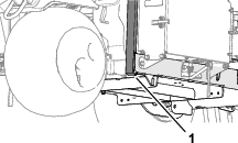
-
Jack the front of the machine off the ground.
-
Position the jack stands or hardwood blocks under the front of the frame to support the machine.
Jacking the Rear End
-
Prepare the machine for maintenance; refer to Preparing the Machine for Maintenance.
-
Chock the front tire to prevent the machine from moving.
Important: To prevent wheel motor damage, do not use rear wheel motor as a jacking point.
-
Place the jack securely under the frame plate just inside of the rear wheel (Figure 139).
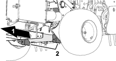
Note: If available, use a hoist to lift the rear of the machine. Use the eyelets in the coring-head bearing housings as hoist attachment points (Figure 3).
-
Jack (or lift) the rear of the machine off the ground.
-
Position the jack stands or hardwood blocks under the frame to support the machine.
Removing the Belt Cover
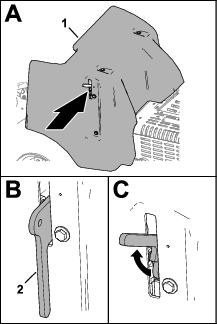
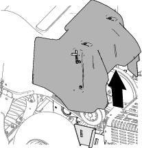
Installing the Belt Cover
-
Align the mount bracket of the belt cover with the cover-support bracket of the machine frame (Figure 144).
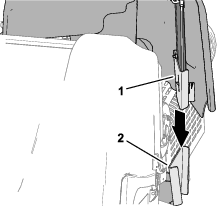
-
Lower the belt cover (Figure 145).
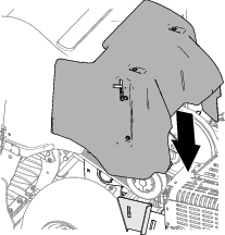
-
Fully lower the latch handle to secure the cover (Figure 146).
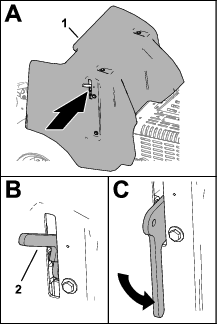
-
If your machine has the CE belt-cover latch lanyard, thread the lanyard bolt into the hole in the cover latch, and tighten the bolt (Figure 147).
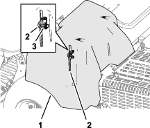
Removing the Coring-Head Cover
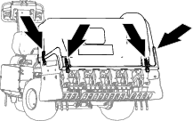
-
If you machine has CE latch locks, loosen the lock-plate bolt until the lock plate clears the slot in the side of the coring-head cover (Figure 149).
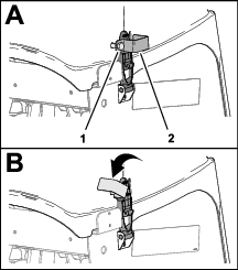
-
Rotate the lock plate to clear the latch (Figure 149).
-
Repeat 1 and 2 at the other side of the cover.
-
Unlatch the coring head cover at the 4 latch location (Figure 148 and Figure 150).
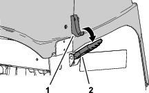
-
Lift the coring-head cover from the machine (Figure 151).
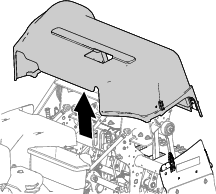
Installing the Coring-Head Cover
-
Align the coring-head cover to the machine as shown in Figure 152.

-
Latch the coring head cover at the 4 latch location (Figure 153).
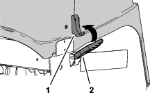
-
If you machine has CE latch locks, rotate the lock plate until it aligns with the slot in the side of the coring-head cover (Figure 154).
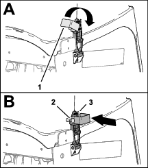
-
Tighten the lock-plate bolt (Figure 154).
-
Repeat steps 3 and 4 at the other side of the cover.
Lubrication
Checking the Coring Head Bearings
| Maintenance Service Interval | Maintenance Procedure |
|---|---|
| Every 500 hours |
|
| Yearly |
|
The machine has no grease fittings that must be lubricated.
Important: Bearings rarely fail from defects in materials or workmanship. The most common reason for failure is moisture and contamination working its way past the protective seals. Bearings that are greased rely upon regular maintenance to purge harmful debris from the bearing area. Sealed bearings rely on an initial fill of special grease and a robust integral seal to keep contaminants and moisture out of the rolling elements.
The sealed bearings require no lubrication or short term maintenance. This minimizes routine service required and reduces the potential of turf damage due to grease contamination. These sealed bearing packages provide good performance and life under normal use, but periodic inspections of bearing condition and seal integrity should be conducted to avoid downtime. Inspect the bearings seasonally and replace them if they are damaged or worn. Bearings should operate smoothly with no detrimental characteristics such as high heat, noise, looseness, or rust weeping.
Due to the operating conditions these bearing/seal packages are subject to (e.g., sand, turf chemicals, water, impacts, etc.) they are considered normal wear items. Bearings that fail due to causes other than defects in materials or workmanship are typically not covered under warranty.
Note: You can negatively affect bearing by using improper wash down procedures. Do not wash down the machine when it is still hot and avoid directing high-pressure or high volume spray at the bearings.
It is common for new bearings to purge some grease out the seals on a new machine. This purged grease turns black in color due to collection of debris and not due to excessive heat. It is good practice to wipe this excess grease from the seals after the initial 8 hours. There may always appear to be a wet area around the seal lip. This is not detrimental to bearing life, and keeps the seal lip lubricated.
Engine Maintenance
Engine Safety
-
Shut off the engine before checking the oil or adding oil to the crankcase.
-
Do not change the governor speed or overspeed the engine.
Servicing the Air Cleaner
| Maintenance Service Interval | Maintenance Procedure |
|---|---|
| Every 25 hours |
|
| Every 100 hours |
|
Removing the Filters
-
Prepare the machine for maintenance refer to Preparing the Machine for Maintenance.
-
Clean around the air cleaner to prevent dirt from getting into the engine and causing damage.
-
Unscrew the knob and remove the air-cleaner cover (Figure 155).
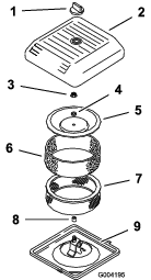
-
Carefully slide the foam pre-filter off the paper element (Figure 155).
-
Unscrew the cover nut and remove the cover, spacer, and paper filter (Figure 155).
Cleaning the Foam Pre-Filter
Important: Replace the foam element if it is torn or worn.
-
Wash the foam pre-filter in liquid soap and warm water. When clean, rinse it thoroughly.
-
Dry the pre-filter by squeezing it in a clean cloth (do not wring).
-
Put 3 to 6 cl (1 to 2 fl oz) of oil on the pre-filter (Figure 156).
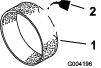
-
Squeeze the pre-filter to distribute the oil.
-
Inspect the paper filter for tears, an oily film, and damage to the rubber seal (Figure 157).
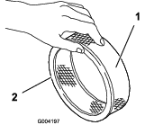
Important: Never clean the paper element. Replace the paper element if it is dirty or damaged.
Installing the Filters
Important: To prevent engine damage, always operate the engine with the complete foam and paper air cleaner assembly installed.
-
Carefully slide the foam pre-filter onto the paper filter (Figure 158).
-
Place the air cleaner assembly onto the air cleaner base.
-
Assemble the cover, spacer, and cover nut.
-
Torque the nut to 11 N∙m (95 in-lb).
-
Install the air cleaner cover and secure with the knob.
Engine Oil Specification
Oil Type: High-quality, detergent engine oil API service SJ or higher
Oil viscosity: Refer to the table below that follows:
Checking the Engine-Oil Level
| Maintenance Service Interval | Maintenance Procedure |
|---|---|
| Before each use or daily |
|
The engine is shipped with oil in the crankcase; however, check the oil level before and after the engine is first started.
Use high-quality engine oil as described in Engine Oil Specification.
Important: Do not overfill the crankcase with oil .Do not run the engine with the engine-oil level below the low mark.
Note: The best time to check the engine oil is when the engine is cool before it has been started for the day. If it has already been run, allow the oil to drain back down to the sump for at least 10 minutes before checking.
-
Prepare the machine for maintenance refer to Preparing the Machine for Maintenance.
-
Allow the engine to cool.
-
Clean around the oil-fill cap and dipstick (Figure 160).
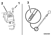
-
Remove the dipstick, wipe it clean, and install until it is fully seated.
-
Remove the dipstick and check the oil level.
The engine-oil level should be between the ‘‘F’’ full and ‘‘L’’ low marks on the dipstick.
-
If the oil level is below the ‘‘L’’ low mark, remove the oil-fill cap and add the specified oil until the level reaches the ‘‘F’’ full mark on the dipstick.
-
Install the oil-fill cap and dipstick.
Changing the Engine Oil and Filter
Draining the Engine Oil
| Maintenance Service Interval | Maintenance Procedure |
|---|---|
| After the first 50 hours |
|
| Every 100 hours |
|
Crankcase capacity: approximately 1.9 L (2.0 US qt) with the filter.
-
Start the engine and let it run for 5 minutes. This warms the oil so that it drains better.
-
Park the machine so that the drain side is slightly lower than the opposite side to ensure that the oil drains completely, shut off the engine, fully raise and latch the handlebar to engage the parking brake, and remove the key.
-
Place a pan below the oil-drain plug, and remove the plug (Figure 161).
Note: Allow the oil to fully drain.
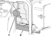
-
Thread the oil-drain plug into the engine, and tighten the plug.
Note: Discard the used oil at a certified recycling center.
Changing the Oil Filter
-
Place a shallow pan under the oil filter, and remove the filter (Figure 161).
Note: Discard the used oil filter at a certified recycling center.
-
Wipe clean the surface of the filter adapter.
-
Fill the new oil filter to bottom of the threads with the specified oil.
-
Allow the filter to absorb the oil for 2 minutes, then pour out the excess oil.
-
Apply a thin coat of new oil to the gasket on the filter.
-
Threads the oil filter onto the filter adapter until the gasket contacts the filter adapter (Figure 161), then tighten the filter an additional 1/2 turn.
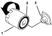
Adding Engine Oil
-
Clean the area around the oil-fill cap and dipstick (Figure 163).
-
Remove the oil-fill cap and slowly pour approximately 80% of the specified amount of oil in through the valve cover.
-
Slowly add additional oil to bring the level to the F (full) mark on the dipstick; refer to Engine Oil Specification and Checking the Engine-Oil Level.
Important: Do not overfill the crankcase with oil.
-
Install the oil-fill cap and dipstick.
Servicing the Spark Plugs
| Maintenance Service Interval | Maintenance Procedure |
|---|---|
| Every 200 hours |
|
Removing the Spark Plugs
-
Prepare the machine for maintenance refer to Preparing the Machine for Maintenance.
-
Pull the wires off the spark plugs (Figure 164).
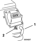
-
Clean around the spark plugs.
-
Use a spark-plug socket to remove both spark plugs and metal gaskets.
Checking the Spark Plugs
Spark-plug type: Champion RC12YC or equivalent
Air Gap: 0.75 mm (0.03 inch)
-
Look at the center of both spark plugs (Figure 165). If you see light brown or gray on the insulator, the engine is operating properly. A black coating on the insulator usually means the air cleaner is dirty.
Important: Never clean the spark plugs. Always replace the spark plugs when they have a black coating, worn electrodes, an oily film, or cracks.
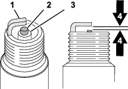
-
Check the gap between the center and side electrodes.
-
Bend the side electrode if the gap is not correct.
Installing the Spark Plugs
Ensure that the air gap between the center and side electrodes is correct before installing each spark plug. Use a spark-plug wrench for removing and installing the spark plugs and a gapping tool/feeler gauge to check and adjust the air gap. Install new spark plugs if necessary.
-
Thread the spark plugs into the spark-plug holes of the engine.
-
Use a spark-plug socket and torque wrench to torque the spark plugs to 27 N∙m (20 ft-lb).
-
Assemble the spark-plug wires onto the spark plugs (Figure 166).
Cleaning the Engine Screen
| Maintenance Service Interval | Maintenance Procedure |
|---|---|
| Before each use or daily |
|
Before each use, check and clean the engine screen. Remove any buildup of grass, dirt, or other debris from the engine air intake screen.
Fuel System Maintenance
Danger
Under certain conditions, fuel and fuel vapors are highly flammable and explosive. A fire or explosion from fuel can burn you and others and can cause property damage.
-
Fill the fuel tank outdoors, in an open area, when the engine is off and is cold. Wipe up any fuel that spills.
-
Do not fill the fuel tank completely full. Add fuel to the fuel tank until the level is 25 mm (1 inch) below the top of the tank, not the filler neck. This empty space in the tank allows the fuel to expand.
-
Never smoke when handling fuel, and stay away from an open flame or where a spark may ignite fuel fumes.
-
Store fuel in a clean, safety-approved container and keep the cap in place.
Replacing the Fuel Filter
| Maintenance Service Interval | Maintenance Procedure |
|---|---|
| Every 100 hours |
|
Important: Never install a dirty filter if it is removed from the fuel line.
-
Prepare the machine for maintenance refer to Preparing the Machine for Maintenance.
-
Close the fuel-shutoff valve (Figure 167).
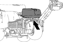
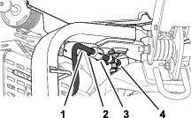
-
Squeeze the ends of the hose clamps together and slide them away from the filter.
-
Remove the filter from the fuel hoses.
-
Align the fuel filter with the arrow pointing toward the engine, and assemble the fuel hose over the filter fittings.
-
Position the hose clamps close to the fuel filter, and tighten the clamp.
-
Wipe up any spilled fuel.
-
Open the fuel-shutoff valve.
Draining the Fuel Tank
Danger
In certain conditions, fuel is extremely flammable and highly explosive. A fire or explosion from fuel can burn you and others and can damage property.
-
Drain fuel from the fuel tank when the engine is cold. Do this outdoors in an open area. Wipe up any fuel that spills.
-
Never smoke when draining fuel, and stay away from an open flame or where a spark may ignite the fuel fumes.
-
Prepare the machine for maintenance refer to Preparing the Machine for Maintenance.
-
Close the fuel-shutoff valve (Figure 168).
-
Loosen the hose clamp at the fuel filter and slide it up the fuel line away from the fuel filter.
-
Pull the fuel line off the fuel filter.
-
Open the fuel-shutoff valve and allow fuel to drain into a fuel can or drain pan.
Note: Now is the best time to install a new fuel filter because the fuel tank is empty.
-
Assemble the fuel hose over the filter fitting.
-
Position the hose clamp close to the fuel filter, and tighten the clamp.
Electrical System Maintenance
Electrical System Safety
-
Disconnect the battery before repairing the machine. Disconnect the negative terminal first and the positive last. Connect the positive terminal first and the negative last.
-
Charge the battery in an open, well-ventilated area, away from sparks and flames. Unplug the charger before connecting or disconnecting the battery.
-
Wear protective clothing and use insulated tools.
Servicing the Battery
Cleaning the Battery
| Maintenance Service Interval | Maintenance Procedure |
|---|---|
| Yearly |
|
Keep the top of the battery clean.
-
Unlatch and open the battery-compartment door (Figure 169).
-
Clean the top of the battery with a brush dipped in ammonia or bicarbonate of soda solution.
Important: Do not remove the fill caps while cleaning.
-
Thoroughly flush the surface of the battery and battery compartment with clean water.
-
Close and latch the battery-compartment door.
Checking the Battery Connections
| Maintenance Service Interval | Maintenance Procedure |
|---|---|
| Yearly |
|
Warning
Battery terminals or metal tools could short against metal tractor components, causing sparks. Sparks can cause the battery gasses to explode, resulting in personal injury.
-
When removing or installing the battery, do not allow the battery terminals to touch any metal parts of the machine.
-
Do not allow metal tools to short between the battery terminals and metal parts of the machine.
Warning
Incorrect battery cable routing could damage the machine and cables causing sparks. Sparks can cause the battery gasses to explode, resulting in personal injury.
-
Always disconnect the negative (black) battery cable before disconnecting the positive (red) cable.
-
Always connect the positive (red) battery cable before connecting the negative (black) cable.
-
Unlatch and open the battery-compartment door (Figure 170).
-
Check that the battery-cable clamps are secure.
Tighten loose battery-cable clamps hardware.
-
Check the battery-cable clamps and battery terminals for corrosion.
-
If the terminals are corroded, remove the negative battery cable.
-
Remove the positive battery cable.
-
Clean cable clamps and battery terminals.
-
Connect the positive battery cable.
-
Connect the negative battery cable.
-
Coat the cable terminals and battery posts with Grafo 112X skin-over grease (Toro Part No. 505-47).
-
Close and latch the battery-compartment door.
Replacing the Fuses
The electrical system is protected by fuses. If a fuse opens, check the component and wiring for a short circuit to ground.
-
Unlatch and open the battery-compartment door (Figure 171).
-
Remove the cover from the fuse block (Figure 172).
Note: The fan fuse is located in-line behind the battery (Figure 173).
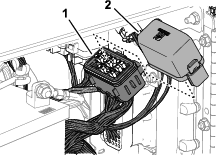
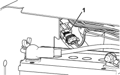
-
Remove the open fuse.
-
Install a new fuse of a rated amperage indicated on the fuse block decal.
-
Assemble the cover onto the fuse block (or onto the in-line fan fuse).
-
Close and latch the battery compartment door.
Drive System Maintenance
Checking the Tire Pressure
| Maintenance Service Interval | Maintenance Procedure |
|---|---|
| Every 50 hours |
|
-
Prepare the machine for maintenance refer to Preparing the Machine for Maintenance.
-
Check to ensure that the air pressure in all tires is 83 kPa (12 psi). Check the tires when they are cold to get the most accurate pressure reading.
Important: Uneven tire pressure can cause uneven coring depth.
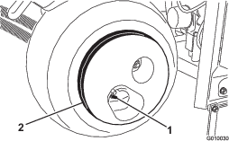
Caution
The wheel weight is very heavy, 33 kg (73 lb).
Use caution when removing it from the tire assembly.
Belt Maintenance
Inspecting the Belts
| Maintenance Service Interval | Maintenance Procedure |
|---|---|
| Yearly |
|
The drive belts of the machine are durable. However, the normal exposure to UV radiation, ozone, or incidental exposure to chemicals can deteriorate the rubber over time and lead to premature wear or material loss (i.e., separated or missing belt plies).
-
Remove the belt cover; refer to Removing the Belt Cover.
-
Inspect the hydraulic-pump, jackshaft, and crankshaft belts (Figure 175) for damage, wear, excessive cushion cracks, or large embedded debris.
Note: Replace the belt(s) when needed.
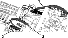
-
Install the belt cover; refer to Installing the Belt Cover.
Adjusting the Pump Belt
| Maintenance Service Interval | Maintenance Procedure |
|---|---|
| After the first 8 hours |
|
-
Prepare the machine for maintenance refer to Preparing the Machine for Maintenance.
-
Remove the belt cover; refer to Removing the Belt Cover.
-
Loosen the flange-head capscrew and flange locknut that secure the idler pulley for the hydraulic-pump belt, until the bolt moves in the slot of the idler support (Figure 176).
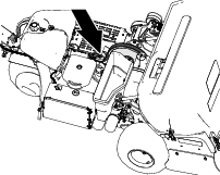
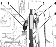
-
Tap the top of the idler pulley and allow the tensioning spring to adjust the belt tension.
Important: Do not apply more belt tension than the tensioning spring applies, or component damage may result.
-
Torque the flange-head capscrew and flange locknut to 37 to 45 N∙m (27 to 33 ft-lb).
-
Install the belt cover; refer to Installing the Belt Cover.
Hydraulic System Maintenance
Hydraulic System Safety
-
Seek immediate medical attention if fluid is injected into skin. Injected fluid must be surgically removed within a few hours by a doctor.
-
Ensure that all hydraulic-fluid hoses and lines are in good condition and all hydraulic connections and fittings are tight before applying pressure to the hydraulic system.
-
Keep your body and hands away from pinhole leaks or nozzles that eject high-pressure hydraulic fluid.
-
Use cardboard or paper to find hydraulic leaks.
-
Safely relieve all pressure in the hydraulic system before performing any work on the hydraulic system.
Relieving Hydraulic Pressure
-
Support the coring head with the service latch; refer to Supporting the Coring Head with the Service Latch.
-
Shut off the engine.
-
Move the ignition switch to the RUN position.
-
In the InfoCenter, navigate to the MAIN MENU (Figure 177).
-
Press the center InfoCenter button until the SERVICE option is selected, and press the right button.
Note: The coring head lowers until it is fully supported by the service latch.
-
Press the center InfoCenter button until the SERVICE LOWER option is selected (Figure 178), press the right button.
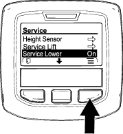
-
Move the key to the STOP position.
Note: Start the engine and run it to raise the coring head hydraulically so that you can stow the service latch; refer to Stowing the Service Latch.
Checking the Hydraulic Lines
| Maintenance Service Interval | Maintenance Procedure |
|---|---|
| Before each use or daily |
|
Before each use, check the hydraulic tubes and hoses for leaks, loose fittings, kinked hoses, loose mounting supports, wear, and weather or chemical deterioration. Make replace worn or damaged hydraulic lines before operating the machine.
Note: Keep the areas around the hydraulic system clean from debris buildup.
Hydraulic Fluid Specifications
The reservoir is filled at the factory with high-quality hydraulic fluid. Check the level of the hydraulic fluid before you first start the engine and daily thereafter; refer to Checking the Engine-Oil Level.
Recommended hydraulic fluid: the manufacturer PX Extended Life Hydraulic Fluid; available in 19 L (5 US gallon) pails or 208 L (55 US gallon) drums.
Note: A machine using the recommended replacement fluid requires less frequent fluid and filter changes.
Alternative hydraulic fluids: If the manufacturer PX Extended Life Hydraulic Fluid is not available, you may use another conventional, petroleum-based hydraulic fluid having specifications that fall within the listed range for all the following material properties and that it meets industry standards. Do not use synthetic fluid. Consult with your lubricant distributor to identify a satisfactory product.
Note: the manufacturer does not assume responsibility for damage caused by improper substitutions, so use products only from reputable manufacturers who will stand behind their recommendation.
| Material Properties: | ||
| Viscosity, ASTM D445 | cSt @ 40°C (104°F) 44 to 48 | |
| Viscosity Index ASTM D2270 | 140 or higher | |
| Pour Point, ASTM D97 | -37°C to -45°C (-34°F to -49°F) | |
| Industry Specifications: | Eaton Vickers 694 (I-286-S, M-2950-S/35VQ25 or M-2952-S) | |
Note: Many hydraulic fluids are almost colorless, making it difficult to spot leaks. A red dye additive for the hydraulic fluid is available in 20 ml (0.67 fl oz) bottles. A bottle is sufficient for 15 to 22 L (4 to 6 US gallons) of hydraulic fluid. Order Part No. 44-2500 from your authorized the manufacturer distributor.
Important: the manufacturer Premium Synthetic Biodegradable Hydraulic Fluid is the only synthetic biodegradable fluid approved by Toro. This fluid is compatible with the elastomers used in Toro hydraulic systems and is suitable for a wide-range of temperature conditions. This fluid is compatible with conventional mineral oils, but for maximum biodegradability and performance, the hydraulic system should be thoroughly flushed of conventional fluid. The oil is available in 19 L (5 US gallon) pails or 208 L (55 US gallon) drums from your authorized the manufacturer distributor.
Checking the Hydraulic-Fluid Level
| Maintenance Service Interval | Maintenance Procedure |
|---|---|
| Before each use or daily |
|
Important: Check the level of the hydraulic fluid before the engine is first started and daily thereafter
The hydraulic reservoir is filled at the factory with high-quality hydraulic fluid.
-
Prepare the machine for maintenance refer to Preparing the Machine for Maintenance.
-
Remove the belt cover; refer to Removing the Belt Cover.
-
Clean the area around the filler neck and the cap of the hydraulic tank (Figure 179). Remove the cap from the filler neck.
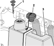
-
Remove the dipstick from the filler neck and wipe it with a clean rag. Insert the dipstick into the filler neck; then remove it and check the level of the fluid. The fluid level should be up to the mark on the dipstick (Figure 180).
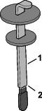
-
If the level is low, add the specified hydraulic fluid to raise the level to the full mark.
-
Install the dipstick and cap onto the filler neck.
-
Install the belt cover; refer to Installing the Belt Cover.
Changing the Hydraulic Fluid and Filters
| Maintenance Service Interval | Maintenance Procedure |
|---|---|
| Every 200 hours |
|
| Every 400 hours |
|
Hydraulic reservoir capacity: approximately 6.6 L (1.75 US gallons)
Important: Do not substitute automotive oil filters or severe hydraulic system damage may result.
Note: Removing the return filter drains the entire fluid reservoir.
-
Prepare the machine for maintenance refer to Preparing the Machine for Maintenance.
-
Place a drain pan under the filters, remove the old filters, and wipe the filter adapter gasket surface clean (Figure 181).
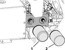
-
Apply a thin coat of clean hydraulic fluid to the gasket on the new filters.
-
Install the hydraulic filters onto the filter adapters. Turn each filter clockwise until the gasket contacts the filter adapter, then tighten each an additional 1/2 turn.
-
Add the specified hydraulic fluid until the fluid level is at the Full mark on the dipstick, refer to Hydraulic Fluid Specifications and Checking the Hydraulic-Fluid Level.
-
Start the engine and run it for 2 minutes to purge air from the system. Shut off the engine, remove the key, and check for hydraulic-fluid leaks.
-
Check the hydraulic fluid level. Add the specified hydraulic fluid to raise the level to the FULL mark on the dipstick, if required.
Note: Do not overfill the hydraulic reservoir with fluid.
-
Install the belt cover; refer to Installing the Belt Cover.
Aerator Maintenance
Checking the Fastener Torque
| Maintenance Service Interval | Maintenance Procedure |
|---|---|
| After the first 8 hours |
|
-
Prepare the machine for maintenance refer to Preparing the Machine for Maintenance.
-
Remove the coring-head cover; refer to Removing the Coring-Head Cover.
-
Check the coring head fasteners, tiller handle fasteners, and wheel lug nuts to ensure that the proper torque is maintained. Fastener torque requirements are listed on the bolt torque decal located on the coring head support channel (Figure 182).
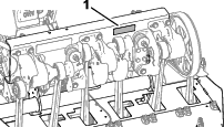
-
Install the coring-head cover; refer to Installing the Coring-Head Cover.
Adjusting the Side Shields
-
Prepare the machine for maintenance refer to Preparing the Machine for Maintenance.
-
Loosen the capscrews and flange locknuts that secure the side shield to coring-head frame (Figure 183).
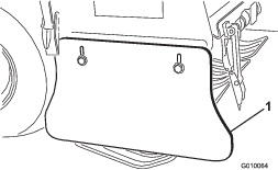
-
Adjust the shield up or down until you measure a 25 to 38 mm (1 to 1.5 inches) between the shield and the ground.
-
Tighten the capscrews and flange locknuts.
-
Repeat steps 2 through 4 at the other side of the machine.
Replacing the Turf Guards
Replace turf guards if they are broken, or worn to less than 6 mm (1/4 inch) thickness. Broken turf guards can catch and tear the turf, damaging it.
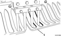
Coring Head Timing
The coring head timing marks are easily identified by the cast-in marks on the 3 bearing housings.
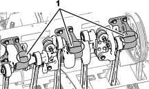
Storage
Storage Safety
-
Before you leave the operator’s position, do the following:
-
Park the machine on a level surface.
-
Fully raise and latch the handlebar to engage the parking brake.
-
Shut off the engine and remove the key (if equipped).
-
Wait for all movement to stop.
-
Allow the machine to cool before adjusting, servicing, cleaning, or storing it.
-
-
Do not store the machine or fuel container where there is an open flame, spark, or pilot light, such as on a water heater or other appliance.
Storing the Machine for less than 30 days
Warning
Charging the battery produces gasses that can explode.
Never smoke near the battery and keep sparks and flames away from it.
-
Prepare the machine for maintenance refer to Preparing the Machine for Maintenance.
-
Disconnect the spark-plug wire.
-
Remove grass, dirt, and grime from the external parts of the entire machine, especially the engine and the hydraulic system. Clean dirt and chaff from the outside of the cylinder-head fins of the engine and blower housing.
-
Service the air cleaner; refer to Servicing the Air Cleaner.
-
Change the engine oil; refer to Changing the Engine Oil and Filter.
-
Change the hydraulic filters and fluid, refer to Changing the Hydraulic Fluid and Filters.
-
Check the tire pressure; refer to Checking the Tire Pressure.
-
Check the condition of the tines.
Storing the Machine for the Season
If you are storing the machine for the season, Perform all the steps in Storing the Machine for less than 30 days and the following:
Preparing the Chassis
-
Check and tighten all bolts, nuts, and screws. Repair or replace any part that is damaged or worn.
-
Wash and dry the entire machine. Remove the tines, and clean and oil them. Spray light oil mist on coring head bearings (crank and damper links).
Important: You can wash the machine with mild detergent and water. Do not pressure-wash the machine. Avoid excessive use of water, especially near the control panel, engine, hydraulic pumps, and motors.
Note: Run the machine with the engine at high idle for 2 to 5 minutes after washing.
-
Paint all scratched or bare metal surfaces. Paint is available from your authorized the manufacturer distributor.
-
Secure service latch if the machine is to be stored for more than a couple of days.
-
Store the machine in a clean, dry garage or storage area. Remove the key from the ignition switch and keep it out of reach of children or other unauthorized users.
-
Cover the machine to protect it and keep it clean.
Preparing the Engine and Fuel System
-
Add a petroleum-based stabilizer/conditioner to fuel in the tank. Follow mixing instructions from stabilizer manufacture. Do not use an alcohol-based stabilizer (ethanol or methanol).
Note: A fuel stabilizer/conditioner is most effective when mixed with fresh fuel and is always used.
Important: Do not store fuel containing stabilizer/conditioner longer than the duration recommended by the fuel-stabilizer manufacturer.
-
Run the engine to distribute conditioned fuel through the fuel system for 5 minutes.
-
Shut off the engine, allow it to cool, and drain the fuel tank; refer to Draining the Fuel Tank.
-
Start the engine and run it until it shuts off.
-
Choke the engine. Start and run the engine until it does not start.
-
Remove the spark plugs and check the condition; refer to Servicing the Spark Plugs. With the spark plugs removed from the engine, pour 2 tablespoons of engine oil into each spark plug hole. Now use the starter to crank the engine and distribute the oil inside the cylinders. Install the spark plugs. Do not install the wires on the spark plugs.
Note: Dispose of fuel properly. Recycle it according to local codes.
Preparing the Battery
-
Remove the battery terminals from the battery posts and remove the battery from the machine.
-
Clean the battery, terminals, and posts with a wire brush and baking soda solution.
-
Coat the cable terminals and battery posts with Grafo 112X skin-over grease (the manufacturer Part No. 505-47) or petroleum jelly to prevent corrosion.
-
Slowly recharge the battery every 60 days for 24 hours to prevent lead sulfation of the battery. To prevent the battery from freezing, make sure it is fully charged. The specific gravity of a fully charged battery is 1.265 to 1.299.
-
Either store the battery on the shelf or on the machine. Leave the cables disconnected if it is stored on the machine. Store it in a cool atmosphere to avoid quick deterioration of the charge in the battery.
Troubleshooting
| Problem | Possible Cause | Corrective Action |
|---|---|---|
| The starter does not crank. |
|
|
| The engine does not start, starts hard, or fails to keep running. |
|
|
| The engine loses power. |
|
|
| The engine overheats. |
|
|
| There is abnormal vibration. |
|
|
| The machine does not drive. |
|
|
| The coring head does not drive. |
|
|
| The head bounces while aerating. |
|
|
| The turf is tufting/tearing on entrance. |
|
|
| There is hole tufting with side eject tines. |
|
|
| The turf is lifting/tearing while aerating. |
|
|
| The front of the hole is dimpled or pushed. |
|
|