
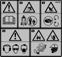
 , which means Caution, Warning,
or Danger—personal safety instruction. Failure to comply with
these instructions may result in personal injury or death.
, which means Caution, Warning,
or Danger—personal safety instruction. Failure to comply with
these instructions may result in personal injury or death.

Maintenance
Caution
If you leave the key in the ignition switch, someone could accidently start the engine and seriously injure you or other bystanders.
Remove the key from the ignition before you do any maintenance.
Recommended Maintenance Schedule(s)
| Maintenance Service Interval | Maintenance Procedure |
|---|---|
| Before each use or daily |
|
| Every 40 hours |
|
| Every 100 hours |
|
| Before storage |
|
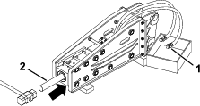
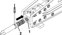
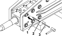
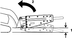
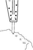
Greasing the Bit
| Maintenance Service Interval | Maintenance Procedure |
|---|---|
| Before each use or daily |
|
Grease type: Chisel paste
-
Park the machine on a level surface and engage the parking brake (if applicable).
-
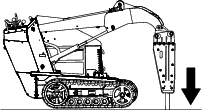
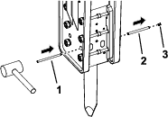
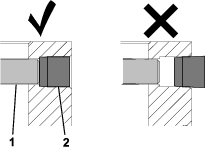
Tilt the breaker so that it is vertical and lower it to the ground to push the bit up into the breaker until it stops.
Important: If you do not push the bit up into the breaker before greasing, grease may fill the space between the top of the bit and the breaker piston. This causes the piston to pressurize the grease and damage the seal when you next use the breaker.
-
Shut off the engine and remove the key.
-
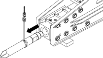
Clean the grease fitting with a rag.
-
Connect a grease gun to the fitting.
-
Pump grease into the fitting until either grease begins to ooze out of the lower bushing and retaining pin or pumping the grease gun becomes difficult.
-
Wipe up any excess grease.
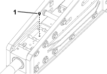
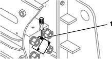
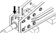
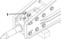
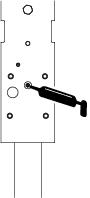
Checking the Nitrogen Charge
| Maintenance Service Interval | Maintenance Procedure |
|---|---|
| Every 100 hours |
|
Warning
Within the breaker is a chamber containing pressurized nitrogen, which under the right circumstances could explode, injuring or killing you or bystanders.
-
Do not take apart the body of the breaker.
-
Do not attempt to charge the chamber yourself. Always take the breaker to an Authorized Service Dealer for charging.
-
Ensure that the breaker is charged only with nitrogen. Other gases can explode.
-
Do not ship the charged breaker via air freight.
Inside the breaker is an accumulator, a chamber of pressurized nitrogen. After several hours of use the pressure may decrease, reducing the performance of the breaker.
Strong vibrations in the auxiliary hydraulic hoses are a sign the pressure is dropping in the chamber. If this should happen, bring the breaker to your Authorized Service Dealer to be charged.
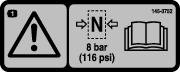
Nitrogen gas pressure: 8 bar (116 psi)
-
Park the machine on a level surface, engage the parking brake (if applicable), and lower the breaker on the ground.
-
Shut off the engine and remove the key.
-
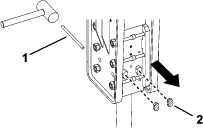
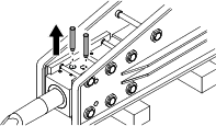
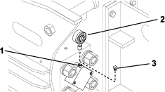
Remove the gas-valve plug from the cylinder cover.
-
Insert a pressure gauge into the gas valve and measure it.
-
If it is low, contact your Authorized Service Dealer to charge it.
Checking the Hydraulic Lines
| Maintenance Service Interval | Maintenance Procedure |
|---|---|
| Before each use or daily |
|
Warning
Hydraulic fluid escaping under pressure can penetrate skin and cause injury. Fluid injected into the skin must be surgically removed within a few hours by a doctor familiar with this form of injury; otherwise, gangrene may result.
-
Keep your body and hands away from pinhole leaks or nozzles that eject high-pressure hydraulic fluid.
-
Use cardboard or paper to find hydraulic leaks; never use your hands.