Safety
Safety-Alert Symbol
The safety-alert symbol (Figure 1) shown in this manual and on the machine identifies important safety messages that you must follow to prevent accidents.

The safety-alert symbol appears above information that alerts you to unsafe actions or situations and is followed by the word DANGER, WARNING, or CAUTION.
DANGER indicates an imminently hazardous situation which, if not avoided, will result in death or serious injury.
WARNING indicates a potentially hazardous situation which, if not avoided, could result in death or serious injury.
CAUTION indicates a potentially hazardous situation which, if not avoided, may result in minor or moderate injury.
This manual uses two other words to highlight information. Important calls attention to special mechanical information and Note emphasizes general information worthy of special attention.
Installation
Preparing the Machine
-
Park the machine on a level surface.
-
Engage the parking brake.
-
Shut off the engine and remove the key.
-
Wait for the engine to cool completely.
-
Disconnect the ground (black) cable from the battery. Then, disconnect the positive (red) cable from the battery.
-
Raise the seat assembly by pushing it forward; refer to the Operator’s Manual.
-
Raise the cargo bed and secure it in the service position using the prop rod; refer to the Operator’s Manual.
-
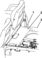
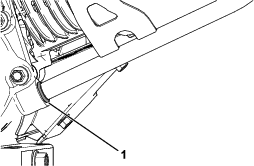
Remove the rear frame panel cover by releasing the latches and lifting the cover from the rear frame (Figure 2).
Removing the Existing Engine
-
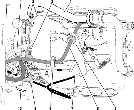
Disconnect the accelerator cable from the engine from the ball joint on the throttle lever and remove the cable from the throttle bracket (Figure 3).
-
Loosen the hose clamp that secures the air-intake hose to the engine and the air-cleaner assembly. Remove the intake hose (Figure 3).
-
Disconnect the oxygen sensor from the engine wire harness (Figure 3).
-
Remove the 2 flange-head bolts securing the exhaust manifold and gasket. Retain the nuts and remove the exhaust assembly Figure 3).
-
Disconnect hoses from the electronic fuel-injected engine (Figure 3):
Important: Record the routing of fuel hoses and hose clamp applications.
-
Disconnect the fuel-supply hose at the fuel injector.
-
Disconnect the pulse hose at the pulse-line filter and remove the hose from the R-clamp.
-
Disconnect the EVAP hose at the throttle body.
-
-
Disconnect the machine wire harness from the engine wire harness secured to the left side of the swing arm under the air-filter assembly.
-
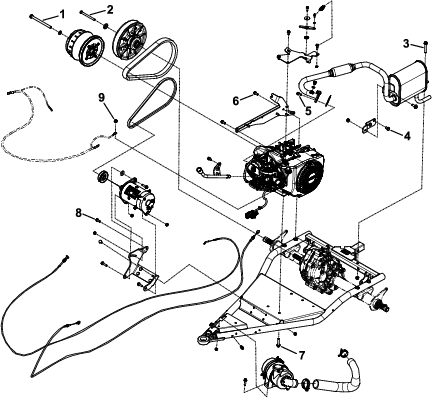
Remove the CVT drive belt, starter/generator belt, and primary clutch from the engine.
-
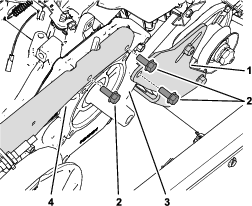
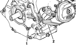
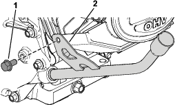
Remove the 2 flange-head bolts that secure the spanner bar to the engine (Figure 4).
-
Remove the flange-head bolt that secures the starter/generator bracket to the engine (Figure 4).
-
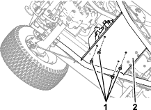
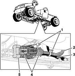
Remove the 4 flange-head bolts that secure the engine to the swing-arm platform (Figure 5).
Note: For assembly purposes, note that the negative battery cable is secured to engine with the left, front engine fastener.
-
Carefully remove the engine from the swing arm and vehicle using an appropriate lifting device.
Important: Make sure to not damage the engine, fuel hoses, control cables, electrical harness or other parts while removing the engine.
Caution
The engine weighs approximately 34.5 kg (76 lb). Lifting the engine by yourself can cause personal injury.
To prevent personal injury, ensure that the engine is properly supported with a lifting device as it is removed from the vehicle.
Installing the New Dipstick Tube
Parts needed for this procedure:
| Dipstick tube (short) | 1 |
| Dipstick tube (long) | 1 |
| Loctite® 620 (0.5 ml) | 1 |
Important: For best results, allow the Loctite® 620 to cure for 24 hours to develop the proper heat resistance.You can accelerate the curing time to 8 hours if the ambient temperatures are above 22°C (71.6°F).
-
Identify the dipstick tube to be used for your vehicle:
-
For lifted vehicles, use the short dipstick tube from the kit.
-
For standard vehicles, use the long dipstick tube from the kit.
-
-
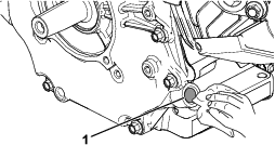
Remove the bolt from the engine-mounting surface (Figure 6).
Retain the bolt.
-
Thoroughly clean the dipstick-tube opening where you install the dipstick tube (Figure 7).
-
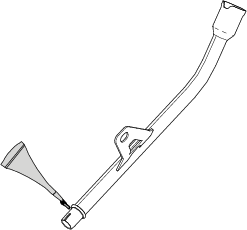
Apply the Loctite® 620 uniformly and evenly around the sealing surface of the dipstick tube (Figure 8).
-
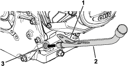
Insert the dipstick tube at an angle into the tube opening (Figure 9).
-
Using a rubber mallet, tap the bracket (item 1) on the dipstick tube (Figure 9) to secure the tube into the engine.
Important: Striking anything but the bracket on the tube could damage the tube.
-
Ensure that the bottom of the dipstick tube is flush with the tube opening (Figure 10).
-
Rotate the dipstick tube so that it is parallel with the engine-mounting surface and secure it using the previously removed bolt (Figure 11).
-
Torque the bolt to 10.7 to 11.3 N∙m (95 to 100 in-lb).
-
Insert the dipstick into the dipstick tube.
-
Ensure that the Loctite® 620 cures properly.
Installing the Engine
-
Install the engine by reversing the steps in Removing the Existing Engine.
Note: Make sure to remove all plugs and covers that are on the hose and engine openings.
-
Torque all fasteners to the correct specifications as shown in Figure 12.
-
Connect the positive (red) cable to the battery.
-
Connect the ground (black) cable to the battery.
-
Make sure the engine oil level is correct.
-
Check the operation of the accelerator cable and adjust if necessary:
-
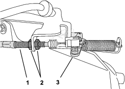
At the throttle cable housing, loosen the forward jam nut and tighten the rear jam nut to increase the low idle (Figure 13).
-
Test the high idle with a tachometer:
-
Ensure that the shift lever is in the NEUTRAL position.
-
Start the engine.
-
Fully press the accelerator pedal and measure the engine speed with a tachometer; the engine speed should be between 3,650 to 3,750 rpm. If it is not, shut off the engine and adjust the cable jam nuts.
Important: Do not lower the high idle. Test with a tachometer to ensure that the high idle is between 3,650 to 3,750 rpm.
-
-
Completing the Installation
Parts needed for this procedure:
| Cable tie | 2 |
-
Connect the machine wire harness to the engine wire harness (Figure 14).
-
Use a cable tie to secure the 2 connectors of the engine wire harness together. Then, use the other cable tie to secure the engine wire harness to the battery ground (black) cable (Figure 14).
-
Install the rear frame panel cover, lower the seat assembly, and lower the cargo bed.