This product complies with all relevant European directives. For details, please see the Declaration of Incorporation (DOI) at the back of this publication.
Note: This kit, when installed to Reelmaster 5010 series Traction Units, is covered by Patent # 7,017,703.
Warning
Bodily injury could occur if the traction unit rolls over.
When operating machine, always use the seat belt and ROPS together.
Installation
Preparing the Machine
-
Park the machine on a level surface, engage the parking brake, and disengage the PTO.
-
Lower the cutting units to the ground.
-
Shut off the engine, remove the key, wait for all parts to stop moving, and allow the engine to cool.
Mounting the Wheel Motor Assemblies
Parts needed for this procedure:
| Right wheel motor | 1 |
| Left wheel motor | 1 |
| Hub | 2 |
| Locknut (1-1/2 inches) | 2 |
| Hydraulic fitting, 45° | 4 |
| Bolt (1/2 x 2-1/4 inches) | 8 |
| Lock washer (1/2 inch) | 8 |
-
Jack up the rear of the machine and support it with jack stands.
-
Remove the 5 lug nuts securing each rear tire to the wheel spindle hub (Figure 1). Remove the tires.
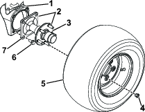
-
Remove the spindle hub assemblies from the wheel housings by removing the 4 flange bolts securing each in place (Figure 1).
Note: You do not need to remove the hubs from the spindles.
Note: Discard the 8 flange bolts and 2 spindle hub assemblies.
-
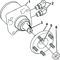
Slide a hub (provided in the kit) onto each of the motors aligning the woodruff key on the motor with the slot on the hub (Figure 2).
-
Secure the hubs to the motors with a locknut (1-1/2 inches). Torque the locknuts to 366 to 447 N∙m (270 to 330 ft-lb).
-
Install two 45° hydraulic fittings into each motor (Figure 2). Position the fittings so that they point straight to the rear.
Note: Make sure that the O-rings are lubricated and in position on all the fittings before installation.
-
Identify the left and right wheel motors. The wheel motor for the right side of the machine is identified with grooves in the outer surface of the motor housing. For further verification, you can identify the left motor by a small yellow sticker or paint mark on the motor housing.
-
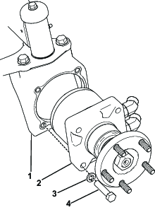
Mount the respective wheel motor assembly to each wheel housing with 4 bolts (1/2 x 2-1/4 inches) and 4 lock washers (1/2 inch) as shown in Figure 3. Torque the bolts to 108 to 136 N⋅m (80 to 100 ft-lb).
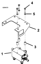
Installing the Manifold
Parts needed for this procedure:
| Manifold | 1 |
| Hydraulic fitting, straight | 7 |
| Diagnostic fitting | 2 |
| Dust cap | 2 |
| Bolt (3/8 x 1-3/4 inches) | 3 |
| Lock washer (3/8 inch) | 3 |
| Spacer | 3 |
-
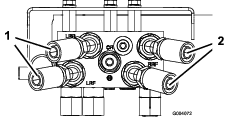
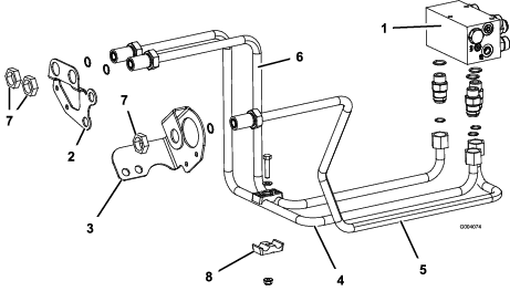
Install 4 straight hydraulic fittings into the rear of the manifold (Figure 4).
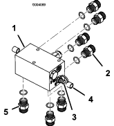
-
Install 2 diagnostic fittings into either side of the manifold along with dust caps (Figure 4).
-
Install 3 straight hydraulic fittings into the bottom of the manifold (Figure 4).
-
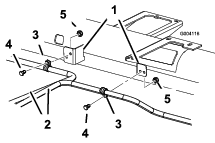
Mount the manifold assembly to the underside of the manifold bracket with 3 bolts (3/8 x 1-3/4 inches), 3 lock washers (3/8 inch), and 3 spacers. Position the spacers between the manifold bracket and the top of the manifold. The manifold is to be positioned so the fittings point to the rear, and down (Figure 5).
Note: Make sure the O-rings are lubricated and in position on all of the fittings before installation.
Installing the Wheel Motor Hoses
Parts needed for this procedure:
| Hydraulic hose | 4 |
-
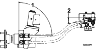
Loosely thread the 45° fitting end of each hydraulic hose onto the straight fittings at the rear of the manifold (Figure 6).
-
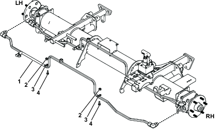
Route the 2 left hoses to the left wheel motor. Connect the upper manifold hose to the upper wheel motor fitting and the lower manifold hose to the lower wheel motor fitting (Figure 7). If the hoses are not properly routed they may come in contact with the tires or rear bumper which will cause damage to the hoses.
Important: Do not cross the hydraulic hoses as they are routed from the manifold to the wheel motors.
-
Repeat the procedure for the right wheel motor. Position the hoses as shown in Figure 8 and tighten all the hose fittings.
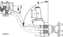
-
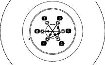
Reinstall the rear tires and torque the lug nuts to 94 to 122 N⋅m (70 to 90 ft-lb) in a crossing pattern (Figure 9).
Important: Check the hose routing to ensure there is proper clearance when the axle is oscillated and when the steering wheel is operated in a full right and left lock turn. The minimum tire to axle clearance should be 1/2 inch (13 mm).
Installing the Manifold Tubes
Parts needed for this procedure:
| Hydraulic tube, Part No. 108-7624 | 1 |
| Hydraulic tube, Part No. 108-7625 | 1 |
| Hydraulic tube, Part No. 108-7626 | 1 |
| Locknut (1-5/16 inches) | 3 |
| Tube clamp halves | 2 |
| Bolt (5/16 x 1-1/2 inches) | 1 |
| Flat washer (5/16 inch) | 1 |
| Flange nut (5/16 inch) | 1 |
-
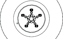
Route the hydraulic tube, Part No. 108-7624, from the left manifold fitting labeled “RF” to the right hole in the right frame bulkhead bracket (Figure 10).
-
Secure the rear of the hydraulic tube to the manifold fitting and the front to the bulkhead with a locknut (1-5/16 inches); refer to Figure 10.
-
Route hydraulic tube, Part No. 108-7626, from the center manifold fitting labeled “REV” to the hole in the left frame bulkhead bracket (Figure 10).
-
Secure the rear of the hydraulic tube to the manifold fitting and the front to the bulkhead bracket with a locknut (1-5/16 inches).
-
Route hydraulic tube, Part No. 108-7625, from the right manifold fitting labeled “LF” to the left hole in the right frame bulkhead bracket (Figure 10).
-
Secure the rear of the hydraulic tube to the manifold fitting and the front to the bulkhead with a locknut (1-5/16 inches).
-
Secure the 2 right bulkhead lines together with the tube clamp halves, bolt (5/16 x 1-1/2 inches), flat washer (5/16 inch), and a flange nut (5/16 inch); refer to Figure 10.
Removing the Front Tube and the Hydraulic Hose
-
Raise the front of the unit and support it on jack stands.
-
Remove the lug nuts securing the wheel assemblies and remove the wheels.
-
Disconnect the hydraulic tube from the top fitting on the front left wheel motor and the bottom fitting on the front right wheel motor (Figure 11).
-
Remove the R-clamps securing the tube to the frame (Figure 11) and the cable ties securing the brake cables to the hydraulic tubes.
-
Disconnect the left hose from the bottom of the variable pump and the hydraulic tube. Also, remove the 45° fitting from the bottom of the variable pump.
Note: You can also remove the right hose to improve clearance for the removal and installation of the front tube. This is not necessary but can aid in the installation of this kit.
Installing the Front Tubes and the Hydraulic Hose
Parts needed for this procedure:
| Hydraulic tube, Part No. 108-7622 | 1 |
| Hydraulic tube, Part No. 108-7623 | 1 |
| Hydraulic fitting, 90° | 1 |
| Hydraulic hose | 1 |
| Cable tie | 3 |
-
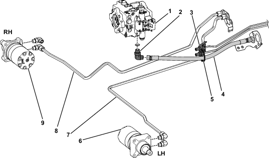
Connect hydraulic tube, Part No. 108-7622, to the right wheel motor fitting and to the right hydraulic tube in the right frame bulkhead (Figure 12).
-
Connect hydraulic tube, Part No. 108-7623, to the left wheel motor fitting and to the left hydraulic tube in the right frame bulkhead (Figure 12).
-
Install a 90° hydraulic fitting into the bottom of the variable pump (Figure 12).
-
Connect the hydraulic hose to the left pump fitting and to the hydraulic tube at left frame bulkhead. If the right hose was removed, connect it at this time.
-
For model
-
Secure the hydraulic hose as follows:
-
For Models 03950 and 03954, secure the hydraulic hose to the bulkhead bracket with a cable tie as shown in Figure 12.
-
For all other models, secure the hydraulic hose to the bottom of the battery tray with a cable tie.
-
-
Install the cable ties to secure the brake cables to the hydraulic tubes.
Checking the Hydraulic Hoses and Tubes
Check the hydraulic tubes and hoses for leaks, loose fittings, kinked lines, and loose mounting supports. Make necessary repairs before operating.
Note: Keep areas around the hydraulic system clean from grass and debris build up.
Warning
Hydraulic fluid escaping under pressure can penetrate skin and cause injury. Fluid accidentally injected into the skin must be surgically removed within a few hours by a doctor familiar with this form of injury or gangrene may result.
-
Keep body and hands away from pin hole leaks or nozzles that eject high pressure hydraulic fluid.
-
Use cardboard or paper to find hydraulic leaks.
-
Install the R-clamps removed previously using 2 screws and lock nuts to secure the hydraulic tubes to the machine frame shown in Figure 13.
-
Install the front tires using the lug nuts previously removed. Torque the lug nuts to 94 to 122 N⋅m (70 to 90 ft-lb) in a crossing pattern (Figure 14).
-
Remove the machine from the jack stands and lower the unit to the floor.
-
Check the hydraulic fluid level. If necessary, add fluid to the bring the level to the full mark on the dipstick. Refer to the Operator's Manual for more information.
-
Ensure that the hydraulic hoses are positioned correctly as follows:
-
Steer the machine fully to the left.
-
Ensure that the hydraulic hoses assembled to the rear wheel motors do not rub against any machine components or the ground, and are not pulling tight or kinking. If needed, adjust the hydraulic fitting angles as necessary.
-
Steer the machine fully to the right and repeat Step 2.
-
-
Operate the machine to test for leaks. Shut down the machine as specified in the Operator's Manual and check for leaks in the hydraulic system.
-
Check the hydraulic fluid level one more time. If necessary, add fluid to the bring the level to the full mark on the dipstick. Refer to the Operator's Manual for more information.
Installing the Decals
Parts needed for this procedure:
| Decal | 2 |
-
Install each decal at locations below as follows:
-
Thoroughly clean the area where you will install the decal.
-
Dampen the area with water or mildly soapy water.
-
Peel the decal from the backing and install it in place.
-
Squeegee across the surface of the decal, starting at the center of the decal and working toward the edges, using overlapping strokes.
-
-
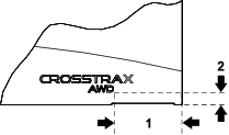
Using the dimensions shown in Figure 15, affix a CROSSTRAX decal to the lower rear corner of each side of the hood.
Operation
-
This kit converts the traction system on your two-wheel drive machine into all-wheel drive. Hydraulic flow from the front left wheel motor routes through the rear right wheel motor and vice versa.
-
If a front wheel slips, the opposite rear wheel must also slip in order for wheel spin to occur, improving traction performance and preventing turf damage.
-
Since the hydraulic flow must route from front to rear wheel motor, there is an increased likelihood of turf scuffing during sharp turns, as the front outside wheel is spinning faster than the rear inside wheel during turns.
-
The rear traction manifold has features to help mitigate turf scuffing, but the operator should practice driving the machine in an inconspicuous area to better understand the characteristics of this kit.
-
Avoid sharp turns while tires are on the fairway surface; instead, plan sharp turns in the rough area.
-
While driving the machine forward, Crosstrax is always engaged. While driving the machine in reverse, the rear motors are bypassed and only the front motors are driving.