| Maintenance Service Interval | Maintenance Procedure |
|---|---|
| Before each use or daily |
|
Introduction
This vehicle is intended to be used by hired, commercial operators primarily off-highway to transport people. Using this product for purposes other than its intended use could prove dangerous to you, your passengers, and bystanders.
Read this information carefully to learn how to operate and maintain your product properly and to avoid injury and product damage. You are responsible for operating the product properly and safely.
Visit www.Toro.com for product safety and operation training materials, accessory information, help finding a dealer, or to register your product.
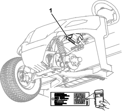
Whenever you need service, genuine Toro parts, or additional information, contact an Authorized Service Distributor or Toro Customer Service and have the model and serial numbers of your product ready. Figure 1 identifies the location of the model and serial numbers on the product. Write the numbers in the space provided.
Important: With your mobile device, you can scan the QR code on the serial number decal (if equipped) to access warranty, parts, and other product information.
This manual uses 2 words to highlight information. Important calls attention to special mechanical information and Note emphasizes general information worthy of special attention.
The safety-alert symbol (Figure 2) appears both in this manual and on the machine to identify important safety messages that you must follow to avoid accidents. This symbol will appear with the word Danger, Warning, or Caution.
-
Danger indicates an imminently hazardous situation which, if not avoided, will result in death or serious injury.
-
Warning indicates a potentially hazardous situation which, if not avoided, could result in death or serious injury.
-
Caution indicates a potentially hazardous situation which, if not avoided, may result in minor or moderate injury.

This product complies with all relevant European directives; for details, please see the separate product specific Declaration of Conformity (DOC) sheet.
It is a violation of California Public Resource Code Section 4442 or 4443 to use or operate the engine on any forest-covered, brush-covered, or grass-covered land unless the engine is equipped with a spark arrester, as defined in Section 4442, maintained in effective working order or the engine is constructed, equipped, and maintained for the prevention of fire.
The enclosed engine owner's manual is supplied for information regarding the US Environmental Protection Agency (EPA) and the California Emission Control Regulation of emission systems, maintenance, and warranty. Replacements may be ordered through the engine manufacturer.
Warning
CALIFORNIA
Proposition 65 Warning
The engine exhaust from this product contains chemicals known to the State of California to cause cancer, birth defects, or other reproductive harm.
Battery posts, terminals, and related accessories contain lead and lead compounds, chemicals known to the State of California to cause cancer and reproductive harm. Wash hands after handling.
Safety
General Safety
-
This product is capable of causing personal injury or death. Always follow all safety instructions to avoid serious personal injury.
-
Improper operation, maintenance, or poor housekeeping of the machine may cause it to become unstable; other factors include terrain conditions, slope, speed, and poor operator judgment.
-
Read and understand the contents of this Operator’s Manual before you start the machine. Ensure that everyone using this product knows how to use it and understands the warnings.
-
Use your full attention while operating the machine. Do not engage in any activity that causes distractions; otherwise, injury or property damage may occur.
-
Do not put your hands or feet near moving components of the machine.
-
Do not operate the machine without all guards and other safety protective devices in place and in good working order.
-
Keep bystanders and children out of the operating area. Never allow children to operate the machine.
-
Stop and shut off the machine and remove the key before servicing or fueling.
-
Improperly using or maintaining this machine can result in injury. To reduce the potential for injury, comply with these safety instructions and always pay attention to the safety-alert symbol
 , which means Caution, Warning,
or Danger—personal safety instruction. Failure to comply with
these instructions may result in personal injury or death.
Safety and Instructional Decals
 |
Safety decals and instructions are easily visible to the operator and are located near any area of potential danger. Replace any decal that is damaged or missing. |



For Models 08916 and 08918 only:

For Models 08914 and 08914TC only:




Setup
Installing the Steering Wheel
Parts needed for this procedure:
| Steering wheel | 1 |
| Screw | 5 |
| Spring | 2 |
| Wheel cover | 1 |
| Wheel clip | 1 |
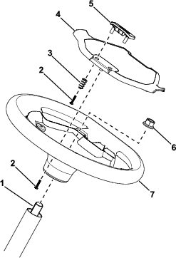
Refer to Figure 3 for this procedure.
-
Place the steering wheel on the steering shaft.
Ensure that the steering wheel is centered (i.e., the flat bottom should be parallel with the ground).
-
Use the locknut to secure the steering wheel to the steering shaft.
-
Torque the locknut to 27 N∙m (20 ft-lb).
-
Use 2 screws and 2 springs to secure the wheel clip to the wheel cover.
-
Use 3 screws to secure the wheel cover to the steering wheel.
-
Torque the 5 screws to 0.6 N∙m (5 in-lb).
Connecting the Battery
Connect the battery; refer to Connecting the Battery.
Checking the Fluid Levels and Tire Pressure
-
Check the engine-oil level before and after you first start the engine; refer to Checking the Engine-Oil Level.
-
Check the brake-fluid level before you first start the engine; refer to Checking the Brake-Fluid Level.
-
Check the transaxle-fluid level before you first start the engine; refer to Checking the Transaxle-Fluid Level.
-
Check the air pressure in the tires; refer to Checking the Tire Pressure.
Burnishing the Brakes
To ensure optimum performance of the brake system, burnish (break-in) the brakes before use.
-
Bring the machine up to full speed, apply the brakes to rapidly stop the machine without locking up the tires.
-
Repeat this procedure 10 times, waiting 1 minute between stops, to avoid overheating the brakes.
Product Overview
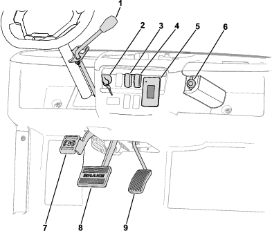
Become familiar with all the controls before you start the engine and operate the machine.
Control Panel
Accelerator Pedal
Use the accelerator pedal to vary the ground speed of the machine. Pressing down the accelerator pedal starts the engine. Pressing the pedal farther increases the ground speed. Releasing the pedal slows the machine, and the engine shuts off.
Note: The forward speed is 26 km/h (16 mph).
Brake Pedal
Use the brake pedal to stop or slow the machine.
Warning
Operating a machine with worn or incorrectly adjusted brakes can may result in personal injury.
If the brake pedal travels within 25 mm (1 inch) of the machine floor board, adjust or repair the brakes.
Parking-Brake Pedal
Push down the pedal to engage the parking brake.
The parking brake disengages when you push the accelerator pedal.
Key Switch
The key switch has 3 positions: OFF, ON, and START.
Horn Switch
Press the horn switch to sound the horn.
Gear-Shift Lever and Gear-Shift Indicator
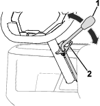
The gear-shift lever can be set to 3 positions on the gear-shift indicator (Figure 5): FORWARD, REVERSE, and NEUTRAL.
Note: The engine starts and runs in any of the 3 positions.
From the NEUTRAL position, you can move the gear-shift lever left to the FORWARD position or right to the REVERSE position (Figure 5).
Important: Always stop the machine before changing gears.
Light Switch
Use the light switch to illuminate the headlights. Push the light switch up to turn on the headlights. Push the light switch down to turn off the lights.
USB Port
Use the USB port to power mobile devices.
Important: When you are not using the USB port, insert the rubber plug to prevent damage to the port.
Display
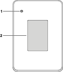
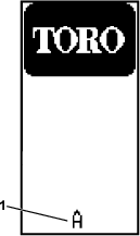
The display shows information about your machine, such as the operating status, various diagnostics, and other information about the machine (Figure 6).
Normally, the indicator light illuminates solid green.
If there are one or more active faults, the indicator light blinks red.
If there is an advisory, the indicator light illuminates solid red.
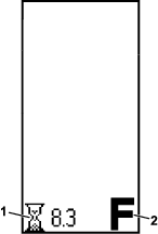
There is a startup screen and run screen on the display (Figure 7 and Figure 8).
Figure 8 shows what you may see on the display when you run the machine. The startup screen displays for a few seconds after you turn the key to the ON position, then the run screen displays.
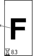
The run screen with the direction position (Figure 9) appears when you change directions.
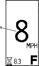
The run screen with the current machine speed (Figure 10) appears when you are driving the machine.
An active fault code (Figure 11) appears on the display if there is an issue with the machine.
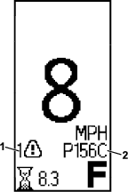
Icon Descriptions
 | Direction—FORWARD position |
 | Direction—NEUTRAL position |
 | Direction—REVERSE position |
 | Hour meter |
 | Active fault |
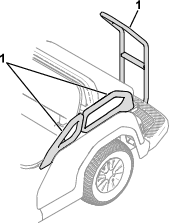
Passenger Handholds
The passenger handholds are located on the outside of each seat and at the rear of the machine (Figure 12).
Note: Specifications and design are subject to change without notice.
| Base weight | 4-passenger model: 398 kg (880 lb), including the Canopy Kit |
| 6-passenger model: 417 kg (920 lb) | |
| 8-passenger model: 482 kg (1,065 lb) | |
| Rated capacity (on level ground) | 4-passenger model: 463 kg (1,020 lb) total, including 90.7 kg (200 lb) operator and 91 kg (200 lb) for each passenger, load, accessories, and attachments |
| 6-passenger model: 694 kg (1,530 lb) total, including 90.7 kg (200 lb) operator and 91 kg (200 lb) for each passenger, load, accessories, and attachments | |
| 8-passenger model: 878 kg (1,935 lb) total, including 90.7 kg (200 lb) operator and 91 kg (200 lb) for each passenger, load, accessories, and attachments | |
| Gross vehicle weight (GVW)—on level ground | 4-passenger model: 861 kg (1,900 lb) |
| 6-passenger model: 1,111 kg (2,450 lb) | |
| 8-passenger model: 1,360 kg (3,000 lb) | |
| Overall width | 112 cm (44 inches) |
| Overall length | 4-passenger model: 277 cm (109 inches) |
| 6-passenger model: 357 cm (140.5 inches) | |
| 8-passenger model: (172.0 inches) | |
| Overall height | Top of steering wheel: 121 cm (47.5 inches) |
| Top of canopy: 188 cm (73.9 inches) | |
| Ground clearance | 21.6 cm (8.5 inches) at the front with no operator |
| 15.7 cm (6.2 inches) at the rear with no operator | |
| Wheel base | 4-passenger model: 166 cm (65.5 inches) |
| 6-passenger model: 246 cm (97 inches) | |
| 8-passenger model: 326 cm (128.5 inches) | |
| Wheel tread (center line to center line) | Front: 90 cm (35.4 inches) |
| Rear: 90 cm (35.4 inches) | |
| Engine speed | Low idle: 1,150 rpm |
| High idle: 3.400 rpm |
Attachments/Accessories
A selection of Toro approved attachments and accessories is available for use with the machine to enhance and expand its capabilities. Contact your Authorized Service Dealer or authorized Toro distributor or go to www.Toro.com for a list of all approved attachments and accessories.
To ensure optimum performance and continued safety certification of the machine, use only genuine Toro replacement parts and accessories. Replacement parts and accessories made by other manufacturers could be dangerous, and such use could void the product warranty.
Operation
Note: Determine the left and right sides of the machine from the normal operating position.
Before Operation
Before Operation Safety
General Safety
-
Never allow children or people who are not trained or do not have the visual, auditory, physical, and mental ability to safely operate or service the machine. Local regulations may restrict the age of the operator and require proof of insurance.
-
The owner is responsible for training all operators and mechanics. Operators of the machine should complete an operator's training program regardless of previous experience operating vehicles.
-
The operator's training program should include the Operator's Manual and emphasize the safety of the operator, passengers, and bystanders; general safety rules; an overview of the equipment, controls, and functions, and how they work when used properly and improperly; surface conditions, slope, and other conditions that could affect the operation of the machine; and an evaluation of operator competency.
-
Become familiar with the safe operation of the equipment, operator controls, and safety signs.
-
Shut off the machine, engage the parking brake, remove the key, and wait for all movement to stop before you leave the operator's position.
-
Allow the machine to cool before adjusting, servicing, cleaning, or storing it.
-
Know how to stop and shut off the machine quickly.
-
Check that all safety devices and decals are in place. Repair or replace all safety devices and replace all illegible or missing decals. Do not operate the machine unless they are present and functioning properly.
-
Inspect the machine periodically to ensure that the safety-interlock system (if equipped) is operating properly.
-
Assess the area where you will use the machine and identify areas where you should not operate it and any hazards to avoid. Train operators to comply with any additional safety practices.
-
Use care when operating the machine where there are pedestrians, bicycles, or motor vehicles, whenever possible. When operating the machine with other vehicles or pedestrians around, you may use mirrors, barriers, lighting, or other measures in these areas.
-
It is the owner's responsibility to survey the environment and operating conditions to determine whether the machine requires lights, and if so, to equip the machine with appropriate lights.
-
The owner is responsible for determining if the operating conditions require the machine to have additional sound-producing and/or visual devices and for providing and maintaining such devices according to the manufacturer's recommendations.
-
At the beginning of each shift using the machine, check the condition of the machine, inspecting the tires, warning devices, lights, battery, speed and directional controllers, brakes, safety interlocks, and steering mechanism. If the machine needs repair or is unsafe in any way, report it immediately to the owner and do not operate the machine until it is in a safe operating condition.
Fuel Safety
-
Use extreme care in handling fuel. It is flammable and its vapors are explosive.
-
Extinguish all cigarettes, cigars, pipes, and other sources of ignition.
-
Do not remove the fuel cap or fill the fuel tank while the engine is running or hot.
-
Do not add or drain fuel in an enclosed space.
-
Do not store the machine or fuel container where there is an open flame, spark, or pilot light, such as on a water heater or other appliance.
-
Before fueling the machine, shut off the engine and allow it to cool. Have the operator and passengers leave the machine before fueling it.
-
If you spill fuel, do not attempt to start the engine; avoid creating any source of ignition until the fuel vapors have dissipated.
-
The owner is responsible for storing and handling liquefied fuels in accordance with ANSI/NFPA 30. Store and handle fuel in accordance with ANSI/NFPA 505 and ANSI/NFPA 30 or as required by local ordinances.
-
Contain fuel spills immediately and according to the appropriate regulations.
-
Ventilate maintenance and storage areas according to local fire codes and ordinances to avoid a fire hazard.
-
Prevent fire and an explosion caused by static electric discharge. Use only non-metal, portable fuel containers approved by the Underwriter's Laboratory (UL) or the American Society for Testing and Materials (ASTM). Use only a funnel that is plastic and has no screen or filter. Store and handle fuel in accordance with ANSI/NFPA 505 and ANSI/NFPA 30 or as required by local ordinances.
-
Static electric discharge can ignite gasoline vapors in an ungrounded fuel container. Remove the fuel container from the machine and place it on the ground, away from the machine before filling. Keep the nozzle in contact with container opening while filling. When practical, remove equipment from trailers or truck beds and refuel them on the ground. If this is not possible, use a portable, plastic fuel container to refuel equipment on a truck bed or trailer.
-
Do not use open flames for checking the electrolyte level in the battery or the fuel level in the tank.
-
Do not operate the machine with a leak in the fuel system.
-
Before disconnecting any part of the engine fuel system, ensure that the fuel-shutoff valve (if equipped) is closed.
Performing Daily Maintenance
Before starting the machine each day, perform the Each Use/Daily procedures listed in Daily Maintenance Checklist.
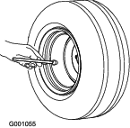
Checking the Tire Pressure
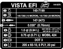
Front and rear tires air pressure specification: 138 kPa (20 psi)
Important: Do not exceed the maximum air pressure indicated on the sidewall of the tire.
Note: The air pressure needed in the tires is determined by the payload that you intend to carry.
-
Check the air pressure in the tires.
-
Use lower air pressure in the tires for lighter payloads, for less soil compaction, for a smoother ride, and to minimize tire marks on the ground.
-
Use higher air pressure in the tires for carrying heavier payloads at higher speeds.
-
-
If necessary, adjust the air pressure in the tires by adding or removing air in the tires.
Adding Fuel
Recommended Fuel
| Type | Unleaded gasoline |
| Minimum octane rating | 87 (US) or 91 (research octane; outside the US) |
| Ethanol | No more than 10% by volume |
| Methanol | None |
| MTBE (methyl tertiary butyl ether) | Less than 15% by volume |
| Oil | Do not add to the fuel |
Use only clean, fresh (no more than 30 days old), fuel from a reputable source.
Important: To reduce starting problems, add fuel stabilizer/conditioner to fresh fuel as directed by the fuel-stabilizer/conditioner manufacturer.
Refer to your engine owner’s manual for additional information.
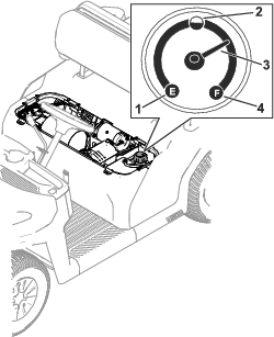
Filling the Fuel Tank
The fuel-tank capacity is approximately 18.9 L (5 US gallons).
-
Park the machine on a level surface.
-
Shift the transmission to the NEUTRAL position.
-
Engage the parking brake.
-
Shut off the machine and remove the key.
-
Clean the area around the fuel-tank cap (Figure 14).
-
Remove the fuel-tank cap.
-
Fill the tank to about 25 mm (1 inch) below the top of tank (bottom of the filler neck).
Note: This space in the tank allows fuel to expand. Do not overfill the fuel tank.
-
Install the fuel-tank cap securely.
-
Wipe up any spilled fuel.
Breaking in a New Machine
| Maintenance Service Interval | Maintenance Procedure |
|---|---|
| After the first 100 hours |
|
Perform the following guidelines to provide proper performance for the machine.
-
Ensure that the brakes are burnished; refer to the burnishing section in Setup.
-
Check the fluid and engine-oil levels regularly. Remain alert for signs that the machine or its components are overheating.
-
After starting a cold engine, let it warm up for about 15 seconds before using the machine.
Note: Allow more time for the engine to warm up when operating in cold temperatures.
-
Vary the machine speed during operation. Avoid fast starts and quick stops.
-
A break-in oil for the engine is not required. Original engine oil is the same type specified for regular oil changes.
-
Refer to for any special, low-hour checks.
-
Check the front suspension positioning and adjust it, if necessary; refer to Adjusting the Wheel Alignment.
During Operation
During Operation Safety
General Safety
-
The owner/operator can prevent and is responsible for accidents that may cause personal injury or property damage.
-
Report all accidents with the machine to the owner.
-
Keep bystanders and children out of the operating area.
-
Passengers should sit in the designated seating positions only. Keep arms and legs within the machine body at all times.
-
The operator should wear substantial, slip-resistant footwear.
-
Use your full attention while operating the machine. Do not engage in any activity that causes distractions; otherwise, injury or property damage may occur.
-
Do not operate the machine while ill, tired, or under the influence of alcohol or drugs.
-
Operate the machine outdoors or in a well-ventilated area only.
-
Before you start the machine, ensure that the transmission is in neutral, the parking brake is engaged, and you are in the operating position.
-
You and your passengers should remain seated whenever the machine is moving. Keep your hands on the steering wheel; your passengers should use the handholds provided.
-
Do not exceed the maximum gross vehicle weight (GVW) of the machine.
-
Carrying oversized loads in the cargo bed reduces the stability of the machine. Do not exceed the carrying capacity of the bed.
-
Operate the machine only in good visibility. Watch for holes, ruts, bumps, rocks, and loose or hidden objects. Reduce the ground speed of the machine when operating on rough, uneven terrain, and near curbs, holes, and other sudden changes in terrain that could overturn the machine. Tall grass can hide obstacles. Use care when approaching blind corners, shrubs, trees, or other objects that may obscure your vision.
-
Identify sharp turns, blind spots, bridge approaches, and other potentially hazardous areas, and post a warning to the operator of the nature of the hazard(s) and the proper precautions to take to avoid the hazard(s).
-
Do not drive the machine near drop-offs, ditches, or embankments. The machine could suddenly roll over if a wheel goes over the edge or if the edge gives way.
-
Keep away from potential hazards, such as edges of ramps and platforms.
-
Always watch out for and avoid low overhangs such as tree limbs, door jambs, overhead walkways, etc.
-
Look behind you before reversing the machine to be sure of a clear path.
-
When using the machine on public roads, follow all traffic regulations and use any additional accessories that may be required by law, such as lights, turn signals, slow-moving vehicle (SMV) signs, and others as required.
-
It can take longer to stop the machine on wet surfaces than on dry surfaces. To dry out wet brakes, drive slowly on a level surface while putting light pressure on the brake pedal.
-
Use extreme caution and slow down when driving the machine in wet or icy areas or on loose terrain could result in reduced traction, steering, stability, and braking. Repair areas of loose terrain, if possible, or close off the area and post a warning to prevent others from operating the machine on those areas.
-
Operating the machine at high speed and then quickly stopping may cause the rear wheels to lock up, which impairs your control of the machine.
-
Do not touch the engine, transmission, muffler, or muffler manifold while the engine is running, or soon after you shut off the engine, because these areas may be hot enough to cause burns.
-
Do not leave a running machine unattended. The machine is considered unattended when you are 7.6 m (25 ft) or more from it, which remains in view, or whenever you leave the machine and it is not within view. Whenever you leave the machine and are within 7.6 m (25 ft) of the machine and it is still in view, set the controls in the NEUTRAL position and engage the parking brake to prevent the machine from moving.
-
Before you leave the operating position, do the following:
-
Park the machine on a level surface.
-
Shift the transmission to the NEUTRAL position.
-
Engage the parking brake.
-
Shut off the machine and remove the key.
-
Wait for all movement to stop.
-
-
If the machine ever vibrates abnormally, stop and shut off the machine immediately, wait for all movement to stop, and inspect for damage. Repair all damage to the machine before resuming operation.
-
Do not park the machine or leave it unattended where it obstructs fire aisles, access to stairways, or fire equipment.
-
Operate the machine only while in the operating position. You and your passengers should remain seated whenever the machine is in motion.
-
Do not allow passengers to distract you either physically or verbally while you are driving the machine.
-
Make starts, stops, turns, or direction reversals smoothly so as not to endanger passengers or lose control of the machine.
-
Always be aware of and watch out for pedestrians. Do not drive the machine in a manner that endangers others.
-
Under all travel conditions, operate the machine at a speed that allows you stop it safely.
-
Yield the right of way to pedestrians, ambulances, fire trucks, vehicles, or other machines in emergency situations.
-
Do not pass another machine traveling in the same direction at intersections, blind spots, or at other dangerous locations.
-
Keep a clear view of the path of travel, observe other traffic and personnel, and maintain a safe clearance.
-
Slow down or stop, as conditions dictate, and activate the sound-producing warning device at cross aisles and when visibility is obstructed at other locations.
-
Do not drive the machine onto any elevator unless specifically authorized to do so. Approach elevators slowly, and then enter squarely after the elevator car is properly leveled. Once on the elevator, set the controls to the NEUTRAL position, shut off the engine, and engage the parking brake. Have all others leave the elevator before you enter or exit in the machine.
-
Do not operate the machine when there is the risk of lightning.
-
Do not add to or modify the machine.
-
Use accessories and attachments approved by The Toro® Company only.
Slope Safety
-
Slopes are a major factor related to loss-of-control and tip-over accidents, which can result in severe injury or death.
-
Survey the site to determine which slopes are safe for operating the machine and establish your own procedures and rules for operating on those slopes. Always use common sense and good judgment when performing this survey.
-
If you feel uneasy operating the machine on a slope, do not do it.
-
Keep all movement on slopes slow and gradual. Do not suddenly change the speed or direction of the machine.
-
Avoid operating the machine on wet terrain. Tires may lose traction. A rollover can occur before the tires lose traction.
-
If possible, avoid turning the machine and use extreme caution on slopes, ramps, or inclines. Travel straight up and down a slope.
-
If you begin to lose momentum while climbing a slope, gradually engage the brakes and slowly reverse the machine straight down the slope.
-
Turning while going up or down a slope can be dangerous. If you must turn on a slope, do it slowly and cautiously. Avoid driving/turning on improperly banked curves.
-
Heavy loads affect stability on a slope. Carry a reduced load and reduce your ground speed when operating on a slope or if the load has a high center of gravity. Secure the load to the cargo bed of the machine to prevent the load from shifting. Take extra care when hauling loads that shift easily (e.g., liquids, rock, sand, etc.).
-
Avoid starting and stopping the machine on a slope. Stopping while going down a slope takes longer than stopping on a level surface. If you must stop the machine, avoid sudden speed changes, which can cause the machine to tip or roll over. Do not engage the brakes suddenly when rolling rearward, as this may cause the machine to overturn.
-
Whenever you operate the machine on steep grades, stay on the designated vehicle paths, which should be marked with a warning of a steep grade.
-
Operating the machine at an excessive speed down a slope will adversely affect its stability. Identify hazardous slopes with a warning in places preceding the beginning of the slope. Use care when approaching a slope, especially when you turn the machine downhill or the downhill slope exceeds 10% (6 degrees) on an unpaved surface or 20% (11 degrees) on a a paved surface. Avoid parking on steep hills.
Loading Safety
-
Do not exceed the gross vehicle weight (GVW) of the machine when operating it with a load in the cargo bed; refer to Specifications.
-
Distribute the load in the cargo bed evenly to improve the stability and control of the machine.
Starting the Engine
-
Sit in the operator seat, insert the key into the key switch, and rotate the key clockwise to the ON or START position.
There are 2 modes of starting the machine:
-
Pedal Start—turn the key switch to the ON position, press down the accelerator pedal, then release your foot from the accelerator pedal.
Note: When you remove your foot from the accelerator pedal, the engine shuts off.
-
Key Start—turn the key switch to the START position and the engine remains on until the is turned to the OFF position.
Note: When using key start mode, you can engage the parking brake and work away from the machine while the engine still runs and the battery holds a charge.
Note: If you turn the key to the START position, the engine cranks until it starts. If the engine cranks for more than 10 seconds, return to the OFF position, and determine the issue (e.g., check the air cleaner for restrictions, ensure that the fuel tank is full, the spark is bad, etc.) before starting the machine again.
-
-
Move the gear-shift selector to the desired direction of travel for the machine.
-
Slowly step on the accelerator pedal.
Stopping the Machine
Important: When stopping the machine on an incline, use the service brakes to stop the machine and engage the parking brake to hold the machine in place. Using the accelerator to stall the machine on the hill can damage the machine.
-
Remove your foot from the accelerator pedal.
-
Slowly press the brake pedal to apply the service brakes until the machine comes to a complete stop.
Note: The stopping distance may vary depending on the machine load and speed.
Parking the Machine
-
Stop the machine using the service brakes by pressing and holding the brake pedal.
-
Engage the parking brake by pushing the parking-brake pedal down.
-
Rotate the key counterclockwise to the OFF position.
-
Remove the key.
After Operation
After Operation Safety
General Safety
-
Before you leave the operating position, do the following:
-
Park the machine on a level surface.
-
Shift the transmission to the NEUTRAL position.
-
Engage the parking brake.
-
Shut off the machine and remove the key.
-
Wait for all movement to stop.
-
-
If, during operation, you find that the machine is unsafe in any way, report it immediately to the owner and do not operate the machine until it is in safe operating condition.
-
Allow the machine to cool before adjusting, servicing, cleaning, or storing it.
Hauling the Machine
-
Use care when loading or unloading the machine into a trailer or a truck.
-
Use full-width ramps for loading the machine into a trailer or a truck.
-
Tie the machine down securely.
Note: Load the machine on the trailer with the front of the machine facing forward. If that is not possible, secure the machine hood to the frame with a strap, or remove the hood and transport and secure it separately or the hood may blow off during transport.
Caution
Loose seats may fall off the machine and trailer when transporting the machine, and the seats may land on another machine or obstruct the roadway.
Ensure that all seats are secured to the vehicle.
Towing the Machine
In case of an emergency, you can tow the machine for a short distance; however, this should not be a standard operating procedure.
Warning
Towing at excessive speeds could cause a loss of steering control, resulting in personal injury.
Never tow the machine at faster than 8 km/h (5 mph).
Note: The power steering does not function, making it difficult to steer.
Towing the machine is a 2-person job. If you must move the machine a considerable distance, transport it on a truck or trailer.
-
Remove the drive belt from the machine.
-
Affix a tow line to the front center of the machine frame.
-
Move the transmission to the NEUTRAL position and disengage the parking brake.
Maintenance
Maintenance Safety
-
Failing to perform regularly scheduled maintenance on the machine may cause driving it to become hazardous. Allow only trained and authorized personnel to maintain, repair, adjust, and inspect the machine.
-
Before you leave the operating position, do the following:
-
Park the machine on a level surface.
-
Shift the transmission to the NEUTRAL position.
-
Engage the parking brake.
-
Shut off the machine and remove the key.
-
Wait for all movement to stop.
-
-
Allow the machine to cool before adjusting, servicing, cleaning, or storing it.
-
If possible, do not perform maintenance while the machine is running. Keep away from moving parts. If you must run the machine to perform a maintenance adjustment, keep your hands, feet, clothing, and any parts of the body away from any moving parts. Keep bystanders away from the machine.
-
Do not operate the machine in an enclosed area without adequate ventilation. Ventilate maintenance and storage areas for the machine to remove flammable vapors (gasses), fumes, and other flammable materials according to applicable fire codes and ordinances.
-
Disconnect the battery before repairing the machine. Disconnect the negative terminal first and the positive last. Connect the positive terminal first and the negative last.
-
Support the machine with jack stands whenever you work under the machine.
-
Immobilize the machine according to the manufacturer's instructions before performing any maintenance.
-
Never interfere with the intended function of a safety device or reduce the protection provided by a safety device.
-
Inspect the machine periodically to ensure that the sound-producing and/or visual device(s) (if so equipped) are maintained in good operating condition.
-
Clean up oil and fuel spills.
-
Avoid fire hazards and have fire protection equipment available.
-
To reduce the potential fire hazard, keep the machine area free of excessive grease, grass, leaves, and accumulation of dirt.
-
Keep all parts of the machine in good working condition and all the hardware properly tightened. Replace all worn or damaged decals.
-
When performing maintenance, use only properly insulated tools.
-
Regularly inspect the brakes, steering mechanisms, speed and directional control mechanisms, warning devices, lights, governors, guards, and safety devices according to the manufacturer's recommendations.
-
Inspect and maintain the battery, motors, speed and directional controllers, limit switches, protective devices, electrical conductors/insulators, and connections according to the manufacturer's recommendation.
-
Before disassembling the fuel system, drain the fuel from the system and turn all the valves to the OFF position to prevent flammable fuel from leaking.
-
Check the fuel systems for leaks and the condition of parts. If you find a leak, do not use the machine until the leak has been repaired.
-
To ensure optimum performance, use only genuine Toro replacement parts and accessories. Replacement parts and accessories made by other manufacturers could be dangerous, and such use could void the product warranty.
-
Modifying and/or adding to the machine without the prior written approval of Toro may adversely affect the safe operation and performance of the machine. If you have modified the machine, you become the original equipment manufacturer of the modified vehicle, and now you have the responsibility to ensure that capacity, operation, warning, maintenance instruction plates, tags, and/or decals are updated accordingly.
-
Do not overspeed the engine by changing the governor settings. To ensure safety and accuracy, have an authorized Toro distributor check the maximum engine speed with a tachometer.
-
Maintain all safety labels in legible condition, as well as decals, nameplates, serial numbers, and the Operator's Manual. Obtain these items from the manufacturer and affix them in their proper place on the machine.
-
After maintaining or repairing the machine, have a qualified and trained mechanic drive it in an authorized area away from other vehicles and pedestrians to ensure that it is adjusted and operates properly.
-
Keep the machine clean to minimize hazards and to make detecting components needing service easier.
-
Record all work performed in a maintenance record log by date, name of person performing maintenance, and type of maintenance. The owner should periodically inspect the log to ensure that its entries are accurate and complete.
-
If major repairs are ever necessary or assistance is required, contact an authorized Toro distributor.
Battery Safety
-
To reduce the potential for fire, keep the batteries and motor area free of excessive grease, grass, leaves, and accumulation of dirt.
-
Remove all jewelry and watches before servicing the batteries.
-
Do not charge the batteries while servicing the machine.
-
Always disconnect all the battery cables before servicing any electrical components; refer to Disconnecting the Battery.
Note: Disconnecting all the battery cables isolates power from the electrical system.
-
Battery electrolyte contains sulfuric acid, which produces hydrogen, a gas that is explosive in certain conditions. Sulfuric acid can burn skin and damage clothing; when emitted in gas form, it can damage your lungs.
-
Always service, store, and charge the machine in a well-ventilated area.
-
Keep sparks and open flames away from the batteries.
-
Do not smoke near the batteries.
-
Do not use an open flame to check the level or leakage of battery electrolyte.
-
Wear proper eye, hand, and face protection.
-
Do not lean over the batteries at any time.
-
Avoid breathing in battery fumes.
-
Fill the batteries where clean water is always available for flushing the skin.
-
If you get electrolyte on your skin or eyes, flush the affected area for 20 minutes with clean water. Remove affected clothing. Seek medical attention immediately.
-
Keep children and pets away from the batteries and electrolyte.
-
-
Electrolyte is poisonous.
-
Do not drink the electrolyte.
-
If electrolyte has been swallowed, have them drink large quantities of water immediately to dilute the electrolyte, if possible.
-
Do not attempt to make them vomit.
-
Call a poison control center and get medical attention immediately.
-
-
When not filling the batteries, keep the battery vent caps tight on the batteries. Do not operate the machine if any of the vent caps are missing or damaged.
-
When removing or installing the batteries, do not allow the battery terminals to touch any metal parts of the machine.
-
Do not allow metal tools to short between the battery terminals and metal parts of the machine.
-
Do not check a battery charge by placing a metal object across the posts. This causes sparks, which can cause an explosion.
-
Always keep the battery retainers in place to protect and secure the batteries.
-
Read and understand the charging instructions before charging the batteries; refer to Charging the Battery. Also, take the following precautions when charging the batteries:
-
Turn the machine key switch to OFF before connecting the charger to a power source.
-
Use only the battery charger supplied with the machine to charge the batteries.
-
Do not charge a damaged or frozen battery.
-
Always unplug the AC power cord from the power outlet before unplugging it from the machine charging receptacle to avoid sparks.
-
If a battery gets hot while charging, begins emitting large amounts of gasses, or spews electrolyte, immediately disconnect the charger power cord from the power outlet. Have the machine serviced by an Authorized Service Dealer before using it again.
-
Recommended Maintenance Schedule(s)
| Maintenance Service Interval | Maintenance Procedure |
|---|---|
| After the first 5 hours |
|
| After the first 8 hours |
|
| After the first 50 hours |
|
| After the first 100 hours |
|
| Before each use or daily |
|
| Every 50 hours |
|
| Every 100 hours |
|
| Every 200 hours |
|
| Every 250 hours |
|
| Every 300 hours |
|
| Every 400 hours |
|
| Every 500 hours |
|
| Every 1,000 hours |
|
Note: Download a free copy of the electrical schematic by visiting www.Toro.com and searching for your machine from the Manuals link on the home page.
Important: Refer to your engine owner’s manual for additional maintenance procedures.
Warning
Failure to properly maintain the machine could result in premature failure of machine systems, causing possible harm to you or bystanders.
Keep the machine well maintained and in good working order as indicated in these instructions.
Caution
Only qualified and authorized personnel should maintain, repair, adjust, or inspect the machine.
-
Avoid fire hazards and have fire-protection equipment present in the work area. Do not use an open flame to check fluid levels or leakage of fuel, battery electrolyte, or coolant.
-
Do not use open pans of fuel or flammable cleaning fluids for cleaning parts.
Caution
If you leave the key in the switch, someone could accidently start the engine and seriously injure you or other bystanders.
Shut off the engine and remove the key from the switch before you perform any maintenance.
Maintaining the Machine under Special Operating Conditions
Important: If the machine is subjected to any of the conditions listed below, perform maintenance twice as frequently:
-
Desert operation
-
Cold climate operation—below 10°C (50°F)
-
Frequent operation in dusty conditions
-
Construction work
-
After extended operation in mud, sand, water, or similar dirty conditions, do the following:
-
Have your brakes inspected and cleaned as soon as possible. This prevents any abrasive material from causing excessive wear.
-
Wash the machine using water alone or with a mild detergent.
Important: Do not use brackish or reclaimed water to clean the machine.
-
Pre-Maintenance Procedures
Preparing the Machine for Maintenance
-
Park the machine on a level surface.
-
Shift the transmission to the NEUTRAL position.
-
Engage the parking brake.
-
Shut off the engine and remove the key.
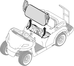
Removing the Seat Assembly
Lift the seat assembly so that the tabs can slide out of the frame brackets (Figure 15).
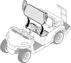
Installing the Seat Assembly
Slide the seat-assembly tabs into the frame brackets and lower the seat assembly (Figure 16).
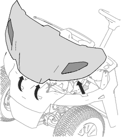
Removing the Hood
Lift the hood from the machine as shown in Figure 17.
Important: Be careful to not damage the headlight wire-harness connectors while you remove the hood. If you need to completely remove the hood from the machine, disconnect the wire-harness connectors from the headlights.
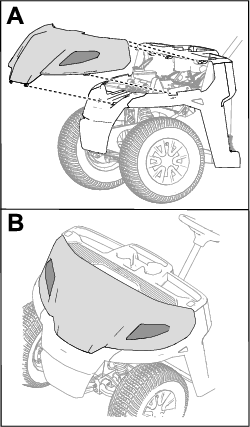
Installing the Hood
-
Ensure that the wire-harness connectors are installed to the headlights,
-
Slide the top of the hood under the dash and inside the fenders.
-
Insert the front hood tabs into the front bumper.
-
Insert the hood side tabs into the fenders by pushing on the hood just below the lights.
Lifting the Machine
Danger
The machine may be unstable when using a jack. The machine could slip off the jack, injuring anyone beneath it.
-
Do not start the machine while the machine is on a jack.
-
Always remove the key from the key switch before getting off the machine.
-
Block the tires when the machine is supported by lifting equipment.
-
Use jack stands to support the machine once you have lifted it.
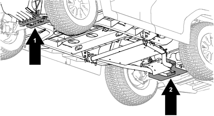
Important: Whenever you run the machine for routine maintenance and/or diagnostics, ensure that the rear wheels of the machine are 25 mm (1 inch) off the ground, with the rear axle supported on jack stands.
Lubrication
Greasing the Front Wheel Bearings
| Maintenance Service Interval | Maintenance Procedure |
|---|---|
| Every 300 hours |
|
Grease specification: Mobilgrease XHP™-222
Removing the Hub and Rotor
-
Lift the front of the machine and support it with jack stands.
-
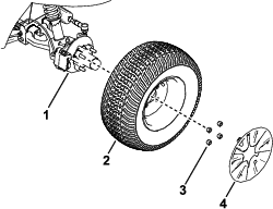
Remove the wheel cover and the 4 lug nuts that secure the wheel to the hub (Figure 20).
-
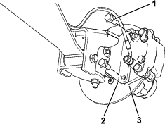
Remove the flange-head bolts (3/8 x 3/4 inch) that secure the bracket for the brake assembly to the spindle and separate the brake from the spindle (Figure 21).
Note: Support the brake assembly before proceeding to the next step.
-
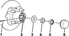
Remove the dust cap from the hub (Figure 22).
-
Remove the cotter pin and nut retainer from the spindle and spindle nut (Figure 22).
-
Remove the spindle nut from the spindle, and separate the hub and rotor assembly from the spindle (Figure 22 and Figure 23).
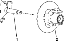
-
Wipe clean the spindle with a rag.
-
Repeat steps 1 through 7 to the hub and rotor at the other side of the machine.
Greasing the Wheel Bearings
-
Remove the outboard bearing from the hub (Figure 24).
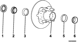
-
Remove the seal, inboard bearing from the hub (Figure 24).
-
Wipe clean the seal and check for wear and damage.
Note: Do not use cleaning solvent to clean the seal. Replace the seal if it is worn or damaged.
-
Clean the bearings and races, and check these parts for wear and damage.
Note: Replace all worn or damaged parts. Ensure that the bearings and races are clean and dry.
-
Clean the cavity of the hub of all grease, dirt, and debris (Figure 24).
-
Pack the bearings with the specified grease.
-
Fill the cavity of hub 50 to 80% full of the specified grease (Figure 24).
-
Assemble the inboard bearing onto the race at the inboard side of the hub and install the seal (Figure 24).
-
Repeat steps 1 through 8 to the bearings for the other hub.
Installing the Hub and Rotor
-
Apply a light coat of the specified grease to the spindle (Figure 25).
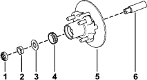
-
Assemble the hub and rotor onto the spindle with the rotor inboard (Figure 25).
-
Assemble the outboard bearing onto the spindle and seat the bearing to the outboard race (Figure 25).
-
Assemble the tab washer onto the spindle (Figure 25).
-
Thread the spindle nut onto the spindle and tighten the nut to 15 N∙m (11 ft-lb), while rotating the hub to seat the bearing (Figure 25).
-
Loosen the spindle nut until the hub rotates freely.
-
Torque the spindle nut to 170 to 225 N∙cm (15 to 20 in-lb).
-
Install the retainer over the nut and check the alignment of the slot in the retainer and the hole in the spindle for the cotter pin (Figure 26).
Note: If the slot in the retainer and the hole in the spindle are not aligned, tighten the spindle nut to align the slot and hole to a maximum torque of 226 N∙cm (20 in-lb) on the nut.
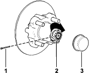
-
Install the cotter pin and bend each legs around the retainer (Figure 26).
-
Install the dust cap onto the hub (Figure 26).
-
Repeat steps 1 through 10 for the hub and rotor at the other side of the machine.
Installing the Brakes and Wheels
-
Clean the 2 flange-head bolts (3/8 x 3/4 inch) and apply a coat of medium-strength thread-locking compound to the threads of the bolts.
-
Align the brake pads to either side of the rotor (Figure 21) and the holes in the caliper bracket with the holes in the brake mount of the spindle frame (Figure 25).
-
Secure the caliper bracket to the spindle frame (Figure 21) using the 2 flange-head bolts (3/8 x 3/4 inch).
Torque the 2 flange-head bolts to 47 to 54 N∙m (35 to 40 ft-lb).
-
Align the holes in the wheel to the studs of the hub and assemble the wheel to the hub with the valve stem outward (Figure 20).
Note: Ensure that the mounting surface of the wheel is flush with the hub.
-
Secure the wheel to the hub using the lug nuts (Figure 20).
Torque the lug nuts to 108 to 122 N∙m (80 to 90 ft-lb).
-
Repeat steps 1 through 5 for the brake and wheel on the other side of the machine.
Engine Maintenance
Engine Safety
-
Shut off the engine, remove the key, and wait for all moving parts to stop before checking the oil or adding oil to the crankcase.
-
Keep your hands, feet, face, clothing, and other body parts away from the muffler and other hot surfaces.
Servicing the Air Cleaner
Servicing the Air-Cleaner Cover
| Maintenance Service Interval | Maintenance Procedure |
|---|---|
| Every 100 hours |
|
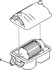
Check the air-cleaner body for damage which could cause an air leak. Replace a damaged air-cleaner body.
Clean the air-cleaner cover and remove the debris from the dust cap (Figure 27).
Replacing the Air-Cleaner Element
| Maintenance Service Interval | Maintenance Procedure |
|---|---|
| Every 100 hours |
|
| Every 200 hours |
|
Note: Service the air-cleaner element more frequently (every few hours) if operating conditions are extremely dusty or sandy.
-
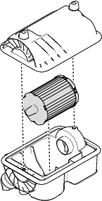
Gently slide the air-cleaner element out of the air-cleaner body (Figure 28).
Note: Avoid knocking the air cleaner into the side of the body.
Important: Do not attempt to clean the air-cleaner element.
-
Inspect the new element for damage by looking into the element while shining a bright light on the outside of the element.
Note: Holes in the element appear as bright spots. Inspect the element for tears, an oily film, or damage to the rubber seal. If the element is damaged, do not use it.
-
Carefully slide the element into the air-cleaner body.
Important: Do not press on the soft inside area of the element.
-
Install the air-cleaner cover (Figure 28).
Servicing the Engine Oil
Engine-Oil Specifications
Crankcase Capacity: 0.71 L (0.75 US qt)
Oil Type: API service class SJ or higher detergent oil
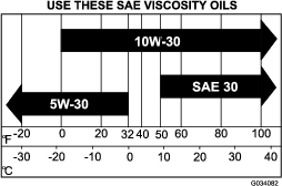
Viscosity: See the table below.
Checking the Engine-Oil Level
| Maintenance Service Interval | Maintenance Procedure |
|---|---|
| Before each use or daily |
|
Note: The machine is shipped with oil in the crankcase; however, check the oil before and after you start the engine.
The best time to check the engine oil is when the engine is cool before it has been started for the day. If you have already run the engine, allow the oil to drain back down to the sump for at least 10 minutes before checking. If the oil level is low, add oil to bring the oil level to the Full mark. Do not overfill.
-
Park the machine on a level surface.
-
Engage the parking brake.
-
Shut off the engine and remove the key.
-
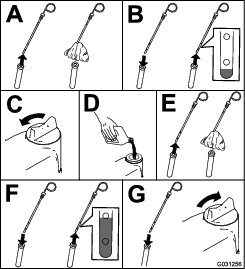
Check the engine-oil level as shown in Figure 30.
Changing the Engine Oil
| Maintenance Service Interval | Maintenance Procedure |
|---|---|
| After the first 5 hours |
|
| Every 50 hours |
|
| Every 100 hours |
|
Note: Change the oil more frequently when operating conditions are extremely dusty or sandy.
Note: Dispose of the used engine oil and oil filter at a certified recycling center.
-
Start the machine and let the engine run for a few minutes.
-
Park the machine on a level surface.
-
Engage the parking brake.
-
Shut off the engine and remove the key.
-
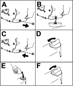
Change the engine oil as shown in Figure 31.
Servicing the Spark Plug
Checking and Replacing the Spark Plug
| Maintenance Service Interval | Maintenance Procedure |
|---|---|
| Every 100 hours |
|
EFI Model Spark Plug Type: Champion XC92YC
Air Gap for EFI Models: 0.76 mm (0.03 inch)
Important: You must replace a cracked, fouled, dirty, or malfunctioning spark plug. Do not sand-blast, scrape, or clean electrodes by using a wire brush because grit may eventually release from the plug and fall into the cylinder. The result is usually a damaged engine.
Note: The spark plug usually lasts a long time; however, the plug should be removed and checked whenever the engine malfunctions.
-
Clean the area around the spark plug so that foreign matter cannot fall into the cylinder when you remove the spark plug.
-
Pull the wire off the terminal of the spark plug.
-
Remove the plug from the cylinder head.
-
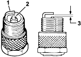
Check the condition of the side electrode, center electrode, and center electrode insulator to ensure that there is no damage (Figure 32).
Note: Do not use a damaged or worn spark plug. Replace it with a new spark plug of the specified type.
-
Set the air gap between the center and side of the electrodes at or 0.76 mm (0.03 inch) as shown in Figure 32.
-
Install the spark plug into the cylinder head, and torque the plug to 27 N∙m (20 ft-lb).
-
Install the spark-plug wire.
Fuel System Maintenance
Checking the Fuel Lines and Connections
| Maintenance Service Interval | Maintenance Procedure |
|---|---|
| Every 500 hours |
|
Check the fuel lines, fittings, and clamps for signs of leaking, deterioration, damage, or loose connections.
Note: Repair any damaged or leaking fuel system component before using the machine.
Replacing the Fuel Filters
| Maintenance Service Interval | Maintenance Procedure |
|---|---|
| Every 400 hours |
|
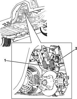
This machine is equipped with a 10 micron and 30 micron fuel filter (Figure 33).
-
Park the machine on a level surface.
-
Engage the parking brake.
-
Shut off the engine and remove the key.
-
Disconnect the battery; refer to Disconnecting the Battery.
-
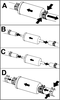
Place a clean container under the fuel filter and replace the fuel filter as shown in Figure 34.
Note: Ensure that the flow-direction arrow on the replacement filter points toward the engine.Ensure that the 30-micron filter is the first in-line filter (i.e., closer to the fuel tank). The 10-micron filter should be the second in-line filter (i.e., closer to the engine).
-
Connect the battery; refer to Connecting the Battery.
Servicing the Carbon Canister
Checking the Air Filter for the Carbon Canister
| Maintenance Service Interval | Maintenance Procedure |
|---|---|
| After the first 50 hours |
|
| Every 200 hours |
|
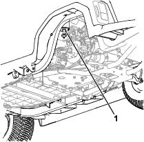
Check the opening at the bottom of the air filter for the carbon canister to ensure that it is clean and free of debris and obstructions (Figure 35).
Clean the air filter for the carbon canister with clean, compressed air.
Electrical System Maintenance
Servicing the Battery
Battery voltage: 12 V with 300 A (cold-cranking) at -18°C (0°F).
-
Always keep the battery clean and fully charged.
-
If the battery terminals are corroded, clean them with a solution of 4 parts water and 1 part baking soda.
-
Apply a light coating of grease to the battery terminals to prevent corrosion.
Accessing the Battery
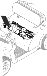
Lift the front seat assembly to access the battery (shown in Figure 36).
Disconnecting the Battery
Warning
Incorrect battery cable routing could damage the machine and cables, causing sparks. Sparks can cause the battery gasses to explode, resulting in personal injury.
-
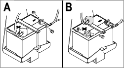
Always disconnect the negative (black) battery cable before disconnecting the positive (red) cable.
-
Always reconnect the positive (red) battery cable before reconnecting the negative (black) cable.
-
Always keep the battery strap in place to protect and secure the battery.
Warning
Battery terminals or metal tools could short against metal machine components, causing sparks. Sparks can cause the battery gasses to explode, resulting in personal injury.
-
When removing or installing the battery, do not allow the battery terminals to touch any metal parts of the machine.
-
Do not allow metal tools to short between the battery terminals and metal parts of the machine.
Disconnect the battery as shown in Figure 37.
Removing the Battery
-
Disconnect the battery cables; refer to Disconnecting the Battery.
-
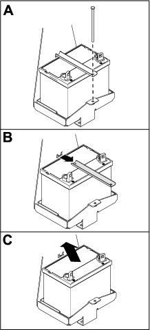
Remove the battery as shown in Figure 38.
Installing the Battery
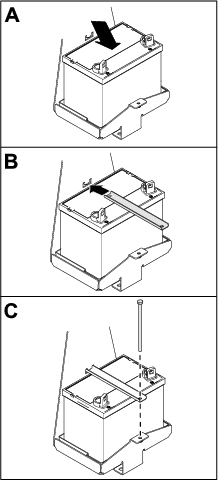
-
Install the battery as shown in Figure 39.
-
Connect the battery cables; refer to Connecting the Battery.
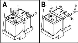
Connecting the Battery
Connect the battery as shown in Figure 40.
Charging the Battery
Warning
Charging the battery produces gasses that can explode.
Never smoke near the battery and keep sparks and flames away from battery.
Important: Always keep the battery fully charged. This is especially important to prevent battery damage when the temperature is below 0°C (32°F).
-
Remove the battery from the machine; refer to Removing the Battery.
-
Connect a 3 to 4 A battery charger to the battery posts. Charge the battery at a rate of 3 to 4 A for 4 to 8 hours (12 V).
Note: Do not overcharge the battery.
-
Install the battery; refer to Installing the Battery.
Storing the Battery
If you store the machine for more than 30 days, remove the battery and charge it fully. Either store it on the shelf or on the machine. Leave the cables disconnected if it is stored on the machine. Store the battery in a cool atmosphere to avoid quick deterioration of the charge in the battery. To prevent the battery from freezing, make sure it is fully charged.
Replacing the Headlight
Specification: See your Parts Catalog.
-
Disconnect the battery; refer to Disconnecting the Battery.
-
Remove the hood.
-
Disconnect the wire-harness connector from the headlight connector (Figure 41).
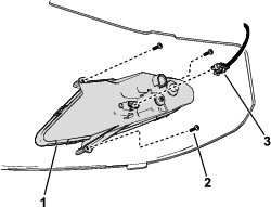
-
Remove the screws that secure the headlight to the hood.
Note: Retain all parts for installation of the new headlight.
-
Remove the old headlight and use the screws to secure the new headlight to the hood.
Torque the screws to 1 N∙m (9 in-lb).
-
Connect the wire-harness connector to the headlight connector (Figure 41).
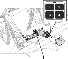
Locating the Fuses
The fuses are located under the hood (Figure 42).
Drive System Maintenance
Maintaining the Tires
| Maintenance Service Interval | Maintenance Procedure |
|---|---|
| Every 100 hours |
|
-
Inspect the tires and rims for signs of wear and damage.
Note: Operating accidents, such as hitting curbs, can damage a tire or rim and also disrupt wheel alignment, so inspect tire condition after an accident.
-
Torque the wheel lug nuts to 108 to 122 N∙m (80 to 90 ft-lb).
Inspecting the Steering and Suspension Components
| Maintenance Service Interval | Maintenance Procedure |
|---|---|
| Every 100 hours |
|
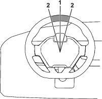
With the steering wheel at the centered position (Figure 43), turn the steering wheel to the left or right. If you turn the steering wheel more than 13 mm (1/2 inch) to the left or right, and the tires do not turn, check the following steering and suspension components to ensure that they are not loose or damaged:
-
Steering shaft to the steering-rack assembly joint
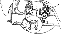
Important: Inspect the condition and security of the pinion-shaft seal (Figure 44).
-
Steering-rack assembly tie rods
Adjusting the Wheel Alignment
| Maintenance Service Interval | Maintenance Procedure |
|---|---|
| Every 100 hours |
|
Preparing to Adjust Camber or Toe-in
-
Check the tire pressure to ensure that the front tires are inflated to 138 kPa (20 psi).
-
Either add weight to the driver's seat equal to the average operator who will run the machine, or have an operator sit on the seat. The weight or operator must remain on the seat for the duration of the adjustment procedure.
-
On a level surface, roll the machine straight back 2 to 3 m (6 to 10 ft) and then straight forward to the original starting position. This allows the suspension to settle into the operating position.
Adjusting the Camber
Owner provided tools: spanner wrench, Toro Part 132-5069; refer to your authorized Toro distributor.
Important: Make the camber adjustments only if you are using a front attachment or if there is uneven tire wear.
Note: This procedure can be performed on the front and rear tires.
-
Check the camber alignment at each wheel; the alignment should be as close to neutral (zero) as possible.
Note: The tires should be aligned with the tread evenly on the ground to reduce uneven wear.
-
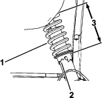
If the wheel camber is out of alignment, use the spanner wrench to rotate the collar on the shock absorber to align the wheel (Figure 45).
Adjusting the Front Wheel Toe-in
Important: Before adjusting toe-in, ensure that the camber adjustment is as close to neutral as possible; refer to Adjusting the Camber.
-
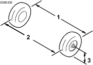
Measure the distance between both of the front tires at the axle height at both the front and rear of the front tires (Figure 46).
-
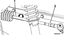
If the measurement does not fall within 0 to +/- 3 mm (0 to +/- 1/8 inch), loosen the jam nuts at the outer end of the tie rods (Figure 47).
-
Rotate both tie rods to move the front of the tire inward or outward.
-
Tighten the tie rod jam nuts when the adjustment is correct.
-
Ensure that there is full travel of the steering wheel in both directions.
Checking the Transaxle-Fluid Level
| Maintenance Service Interval | Maintenance Procedure |
|---|---|
| Every 250 hours |
|
Fluid Type: Mobilfluid™ 424
-
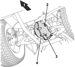
Remove the fill plug on the transaxle (Figure 48).
Note: The fluid level should be even with the bottom of the fill plug.
-
If the fluid level is low, remove the fill plug and add the specified fluid until it runs out of the hole (Figure 48).
-
Replace the fill plug and torque it to 27 to 41 N∙m (20 to 30 ft-lb).
Changing the Transaxle Fluid
| Maintenance Service Interval | Maintenance Procedure |
|---|---|
| Every 500 hours |
|
Fluid Type: Mobilfluid™ 424
Fluid Capacity: 0.75 L (25 fl oz)
-
Align a drain pan under the drain plug (Figure 48).
-
Remove the fill plug (Figure 48).
Note: Retain the fill plug and seal for installation in step 6.
-
Remove the drain plug, and allow the fluid to drain completely (Figure 48).
Note: Retain the drain plug for installation in step 4.
-
Install the drain plug and torque it to 12 to 19 N∙m (9 to 14 ft-lb).
-
Fill the transaxle with the specified fluid and capacity until it is even with the fill hole.
-
Install the fill plug and torque it to 27 to 41 N∙m (20 to 30 ft-lb).
Checking the Neutral Gear-Shift Position
| Maintenance Service Interval | Maintenance Procedure |
|---|---|
| Before each use or daily |
|
| Every 100 hours |
|
When performing routine maintenance and/or engine diagnostics, shift the transaxle into NEUTRAL. The machine has a NEUTRAL position on the gear-shift selector, which controls the neutral in the transaxle. Perform the following steps to ensure that the neutral shift lever operates the transaxle neutral correctly:
-
Set the gear-shift selector to the NEUTRAL position.
-
Rotate the secondary clutch (Figure 54) to see if it spins freely in the NEUTRAL position.
-
Set the gear-shift selector to the FORWARD position.
-
Rotate the secondary clutch (Figure 54) to see if it rotates the rear wheels.
-
Set the gear-shift selector to the REVERSE position.
-
Rotate the secondary clutch (Figure 54) to see if it rotates the rear wheels.
-
If any of these tests fail, proceed to Adjusting the Neutral Gear-Shift Position.
Adjusting the Neutral Gear-Shift Position
-
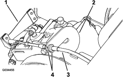
Loosen the jam nuts on the gear-shift cable and adjust them as necessary (Figure 49).
-
Test the gear-shift position by rotating the gear-shift selector to the 3 different positions and check to see if the shift lever (Figure 49) shifts properly when shifting the gears; refer to Adjusting the Neutral Gear-Shift Position.
-
Verify that all of the positions are working correctly by repeating the steps in Checking the Neutral Gear-Shift Position.
Maintaining the Primary Drive Clutch
| Maintenance Service Interval | Maintenance Procedure |
|---|---|
| Every 400 hours |
|
Caution
The dust in the clutch will become airborne and could damage your eyes or you could inhale it, causing breathing difficulties.
Wear safety goggles and a dust mask or other eye and respiratory protection when performing this procedure.
-
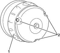
Remove the 3 bolts securing the cover to the clutch, and remove the cover (Figure 50).
Note: Retain the cover and bolts for installation.
-
Thoroughly clean the inside of the cover and the inner components of the clutch using compressed air.
-
Install the clutch cover and secure it with the 3 bolts (Figure 50) that you removed in 1.
Reducing the Top Speed
Caution
The dust in the clutch will become airborne and could damage your eyes or you could inhale it, causing breathing difficulties.
Wear safety goggles and a dust mask or other eye and respiratory protection when performing this procedure.
-
Remove the bolts securing the primary clutch cover as shown in Figure 51.
Important: Use caution when removing the clutch cover; the spring is under compression.
Important: Take note of the X orientation on the clutch covers and clutch assemblies for later installation.
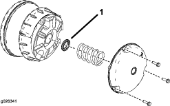
-
Remove the spring.
-
Add or remove spacers to adjust the top speed. Use the following table to determine the amount of spacers needed.
Spacers Top Speed 2 (standard) 16 mph (standard) 3 12 mph 4 9 mph 5 6 mph 6 4 mph Important: Do not operate the machine without at least the thicker spacer in place.
-
Install the spring and clutch cover.
Important: Ensure that the X is placed back in the original location.
-
Torque the bolts to 179 to 228 N∙m (132 to 168 in-lb).
Brake Maintenance
Adjusting the Parking Brake
-
Ensure that the parking brake is disengaged.
-
Using jack stands, lift the rear of the machine; refer to Lifting the Machine.
-
Using 2 wrenches, hold the adjusting post on the caliper in place with 1 wrench, and loosen the jam nut 1/4 turn with the other wrench (Figure 52).
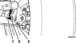
-
While holding the adjusting post and the jam nut in place, turn the adjusting post in to tighten (Figure 52).
Note: Perform this step until you feel drag on the wheel.
-
While holding the adjusting post and the jam nut in place, back off 1/4 turn (Figure 52).
-
While holding the adjusting post and the jam nut in place, tighten the jam nut (Figure 52).
-
Perform steps 1 through 6 to the other side.
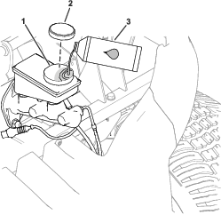
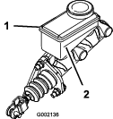
Checking the Brake-Fluid Level
| Maintenance Service Interval | Maintenance Procedure |
|---|---|
| Before each use or daily |
|
Brake-fluid type: DOT 3
Checking the Brakes
| Maintenance Service Interval | Maintenance Procedure |
|---|---|
| Every 100 hours |
|
Important: Brakes are a critical safety component of the machine. Closely inspect them at the recommended service interval to ensure optimum performance and safety.
-
Check the brake lining for wear or damage. If the lining (brake pad) thickness is less than 1.6 mm (1/16 inch), replace the brake lining.
-
Check the backing plate and other components for signs of excessive wear or deformation. Replace any deformed components.
-
Check the brake-fluid level; refer to Checking the Brake-Fluid Level.
Replacing the Service and Parking-Brake Pads
| Maintenance Service Interval | Maintenance Procedure |
|---|---|
| Every 400 hours |
|
Contact your authorized Toro distributor to inspect and possibly replace the service and parking-brake pads.
Changing the Brake Fluid
| Maintenance Service Interval | Maintenance Procedure |
|---|---|
| Every 1,000 hours |
|
Contact your authorized Toro distributor.
Belt Maintenance
Servicing the Drive Belt
Checking the Drive Belt
| Maintenance Service Interval | Maintenance Procedure |
|---|---|
| After the first 8 hours |
|
| Every 200 hours |
|
-
Park the machine on a level surface.
-
Shift the transmission into NEUTRAL.
-
Engage the parking brake.
-
Shut off the engine and remove the key.
-
Rotate and inspect the belt (Figure 55) for signs of excessive wear or damage.
Note: Replace the belt if it is excessively worn or damaged; refer to Replacing the Drive Belt.
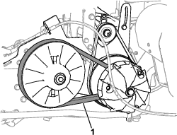
Replacing the Drive Belt
-
Shift the transmission into the NEUTRAL position, engage the parking brake, rotate the key switch to the OFF position, and remove the key.
-
Rotate and route the belt over the secondary clutch (Figure 56).
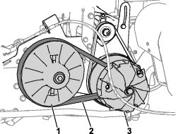
-
Remove the belt from the primary clutch (Figure 56).
Note: Discard the old belt.
-
Align the new belt over the primary clutch.
-
Rotate and route the belt over the secondary clutch.
Adjusting the Starter-Generator Belt
| Maintenance Service Interval | Maintenance Procedure |
|---|---|
| After the first 8 hours |
|
| Every 200 hours |
|
-
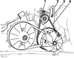
Loosen the pivot nut for the starter generator (Figure 57).
-
Align a pry bar upward between the engine mount and starter.
-
Apply downward pressure to the pry bar to rotate the starter generator down in the pivot-bracket slot (Figure 57) until the belt tension only allows 6 mm (1/4 inch) belt deflection with 44 N∙m (10 ft-lb) of force.
-
Tighten the pivot nut hand-tight and remove the pry bar.
-
Torque the pivot nut to 23 N∙m (17 ft-lb).
Cleaning
Washing the Machine
Wash the machine as needed using water alone or with a mild detergent. You may use a rag when washing the machine.
Important: Do not use brackish or reclaimed water to clean the machine.
Important: Do not use power-washing equipment to wash the machine. Power-washing equipment may damage the electrical system, loosen important decals, or wash away necessary grease at friction points. Avoid excessive use of water near the control panel, engine, and battery.
Important: Do not wash the machine with the engine running. Washing the machine with the engine running may result in internal engine damage.
Storage
Storage Safety
-
Shut off the machine, remove the key, and wait for all movement to stop before you leave the operator's position. Allow the machine to cool before adjusting, servicing, cleaning, or storing it.
-
The owner is responsible for periodically inspecting the charging and storage areas or facilities and review procedures to ensure that the requirements are being followed.
-
Do not operate the machine in an enclosed area without adequate ventilation. Ventilate the maintenance and storage areas for machine to remove flammable vapors (gasses), fumes, and other flammable materials according to applicable fire codes and ordinances.
-
Do not store the machine or fuel container where there is an open flame, spark, or pilot light, such as on a water heater or other appliance.
Storing the Machine
| Maintenance Service Interval | Maintenance Procedure |
|---|---|
| Before each use or daily |
|
-
Position the machine on a level surface, shift the transmission lever to the P (PARK) position, shut off the engine, and remove the key from the key switch.
-
Clean dirt and grime from the entire machine, including the engine area.
Important: You can wash the machine with mild detergent and water. Do not use high-pressure water to wash the machine. Pressure washing the machine may damage the electrical system or wash away necessary grease at friction points. Avoid excessive use of water, especially near the control panel, lights, engine, and battery.
-
Service the air cleaner; refer to Servicing the Air Cleaner.
-
Grease the machine; refer to Greasing the Front Wheel Bearings.
-
Change the engine oil and filter; refer to Servicing the Engine Oil.
-
Check the tire pressure; refer to Checking the Tire Pressure.
-
For storage over 30 days, prepare the fuel system as follows:
-
Add a petroleum based stabilizer/conditioner to the fuel in the tank. Do not use an alcohol-based stabilizer (ethanol or methanol).
Important: Do not store fuel containing stabilizer/conditioner longer than the duration recommended by the fuel stabilizer manufacturer.
-
Run the engine to distribute conditioned fuel through the fuel system for 5 minutes.
-
Shut off the engine, allow it to cool, and drain the fuel tank.
-
Start the engine and run it until it stops.
-
Start and run the engine again until it does not start again.
-
Dispose of drained fuel properly. Recycle as per local codes.
-
-
Remove the spark plugs and check their condition; refer to Servicing the Spark Plug.
-
With the spark plugs removed from the engine, pour 15 ml (2 tablespoons) of engine oil into the spark-plug hole.
-
Use the starter to crank the engine and distribute the engine oil inside the cylinder.
-
Install the spark plugs and tighten each one to the recommended torque; refer to Checking and Replacing the Spark Plug.
Note: Do not install the spark-plug wires on the spark plugs.
-
Check the anti freeze protection and add a 50/50 solution of water and anti freeze as needed for expected minimum temperature in your area.
-
Remove the battery from the chassis, and charge it fully; refer to Servicing the Battery.
Note: Do not connect the battery cables to the battery posts during storage.
Important: The battery must be fully charged to prevent it from freezing and being damaged at temperatures below 0°C (32°F). A fully charged battery maintains its charge for about 50 days at temperatures lower than 4°C (40°F). If the temperatures will be above 4°C (40°F), check the water level in the battery and charge it every 30 days.
-
Check and tighten all fasteners. Repair or replace any part that is damaged.
-
Paint all scratched or bare metal surfaces with paint available from your authorized Toro distributor.
-
Store the machine in a clean, dry garage or storage area.
-
Remove the key from the key switch and put it in a safe place that is out of the reach of children.
-
Cover the machine to protect it and keep it clean.
