
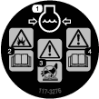
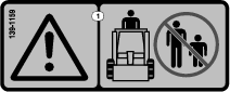
 , which means Caution, Warning,
or Danger—personal safety instruction. Failure to comply with
these instructions may result in personal injury or death.
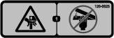
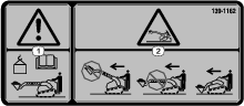
, which means Caution, Warning,
or Danger—personal safety instruction. Failure to comply with
these instructions may result in personal injury or death.


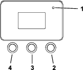


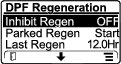
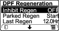
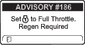
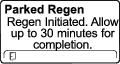
 is displayed in the InfoCenter,
a regeneration is in progress.
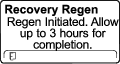
is displayed in the InfoCenter,
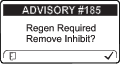
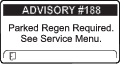
a regeneration is in progress. or ADVISORY #188 displays in the InfoCenter, a regeneration
is requested.
or ADVISORY #188 displays in the InfoCenter, a regeneration
is requested.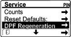
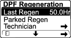
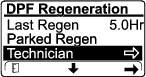
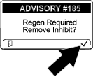
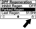
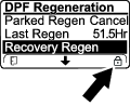
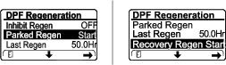

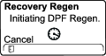


 appears in the lower right corner of the screen as the regeneration
processes.
appears in the lower right corner of the screen as the regeneration
processes.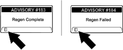

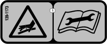
Maintenance
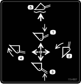
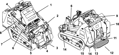
Note: Determine the left and right sides of the machine from the normal operating position.
Maintenance Safety
Caution
If you leave the key in the switch, someone could accidently start the engine and seriously injure you or other bystanders.
Remove the key from the switch before you perform any maintenance.
-
Park the machine on a level surface, disengage the auxiliary hydraulics, lower the attachment, engage the parking brake (if equipped), shut off the engine, and remove the key. Wait for all movement to stop and allow the machine to cool before adjusting, cleaning, storing, or repairing it.
-
Clean up oil or fuel spills.
-
Do not allow untrained personnel to service the machine.
-
Use jack stands to support the components when required.
-
Carefully release pressure from components with stored energy; refer to Relieving Hydraulic Pressure.
-
Disconnect the battery before making any repairs; refer to Using the Battery-Disconnect Switch.
-
Keep your hands and feet away from the moving parts. If possible, do not make adjustments with the engine running.
-
Keep all parts in good working condition and all hardware tightened. Replace all worn or damaged decals.
-
Do not tamper with the safety devices.
-
Attachments can change the stability and the operating characteristics of the machine.
-
Use only genuine Toro replacement parts.
-
If any maintenance or repair requires the loader arms to be in the raised position, secure the arms in the raised position with the hydraulic-cylinder lock(s).
Recommended Maintenance Schedule(s)
| Maintenance Service Interval | Maintenance Procedure |
|---|---|
| After the first 8 hours |
|
| After the first 50 hours |
|
| Before each use or daily |
|
| Every 25 hours |
|
| Every 50 hours |
|
| Every 100 hours |
|
| Every 250 hours |
|
| Every 400 hours |
|
| Every 500 hours |
|
| Every 800 hours |
|
| Every 1,000 hours |
|
| Every 1,500 hours |
|
| Every 3,000 hours |
|
| Yearly or before storage |
|
| Every 2 years |
|
Important: Refer to your engine owner’s manual for additional maintenance procedures.
Pre-Maintenance Procedures
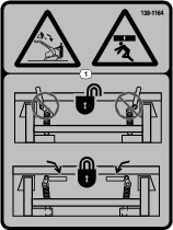
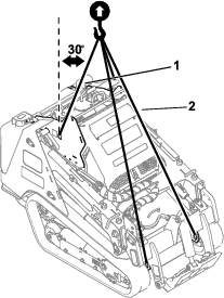
Using the Cylinder Locks
Warning
The loader arms may lower when in the raised position, crushing anyone under them.
Install the cylinder lock(s) before performing maintenance that requires raised loader arms.
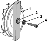
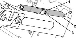
Installing the Cylinder Locks
-
Remove the attachment.
-
Raise the loader arms to the fully raised position.
-
Shut off the engine and remove the key.
-
Loosen the knob securing the cylinder lock to the loader arm.
-
Slide the cylinder lock over the lift-cylinder rod.
-
Repeat step 4 and 6 for the other side of the machine.
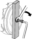
-
Slowly lower the loader arms until the cylinder locks contact the cylinder bodies and rod ends.
-
Secure the loader-valve lock; refer to Loader-Valve Lock.
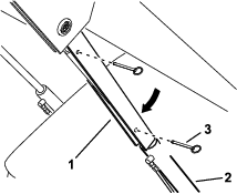
Removing and Storing the Cylinder Locks
Important: Remove the cylinder locks from the rods and fully secure them in the storage position before operating the machine.
-
Start the engine.
-
Raise the loader arms to the fully raised position.
-
Shut off the engine and remove the key.
-
Remove the pins securing the cylinder locks.
-
Remove the cylinder locks from the lift-cylinder rods.
-
Insert the pins into the locks.
-
Place the cylinder locks on the loader arms, with the pin rings beneath the locks, and secure each lock using the hand knob.
-
Lower the loader arms.
Accessing Internal Components
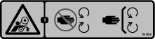
Warning
Opening or removing covers, hoods, and screens while the engine is running could allow you to contact moving parts, seriously injuring you.
Before opening any of the covers, hoods, and screens, shut off the engine, remove the key from the key switch, and allow the engine to cool.
Opening the Hood
-
Park the machine on a level surface, engage the parking brake, and lower the loader arms.
-
Shut off the engine and remove the key.
-
Unlock the hood using the latch key and press the button to release the latch.
-
Lift open the hood
Closing the Hood
-
Lower the hood.
-
Press down the latch to secure the hood.
-
Lock the hood using the latch key.
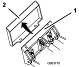
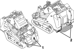
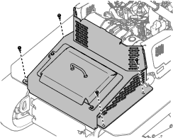
Removing the Rear Cover
-
Remove the 2 bolts securing the top of the rear cover.
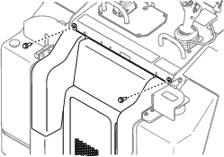
-
Lift the cover out of the slots in radiator bracket.
Removing the Bottom Plate
-
Remove the 2 bolts securing the bottom plate.
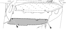
-
Remove the bottom plate.
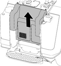
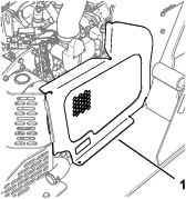
Removing the Front Cover
-
Raise the loader arms and secure them with the cylinder locks.
-
Loosen the 2 bolts securing the front cover to the machine.
-
Slide the cover off the machine.
-
When installing the cover, torque the bolts to 41 N∙m (30 ft-lb).
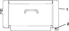
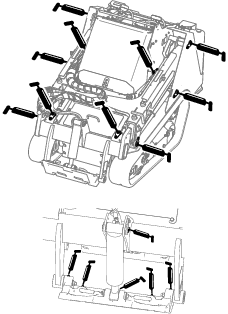
Removing the Front Cover Assembly
-
Raise the loader arms and secure them with the cylinder locks.
-
Open the hood.
-
Remove the 4 bolts securing the cover assembly to the machine.
-
Remove the cover assembly.
Removing the Side Screens
-
Open the hood.
-
Slide the screen out of the front and rear slots.
Lubrication
Greasing the Machine
| Maintenance Service Interval | Maintenance Procedure |
|---|---|
| Before each use or daily |
|
Grease Type: General-purpose grease.
-
Park the machine on a level surface, engage the parking brake, and lower the loader arms.
-
Shut off the engine and remove the key.
-
Clean the grease fittings with a rag.
-
Connect a grease gun to each fitting.
-
Pump grease into the fittings until grease begins to ooze out of the bearings (approximately 3 pumps).
-
Wipe up any excess grease.
Engine Maintenance
Engine Safety
-
Shut off the engine before checking the oil or adding oil to the crankcase.
-
Do not change the engine governor setting or overspeed the engine.
-
Keep your hands, feet, face, other body parts, and clothing away from the muffler and other hot surfaces.
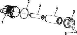
Servicing the Air Cleaner
| Maintenance Service Interval | Maintenance Procedure |
|---|---|
| Before each use or daily |
|
| Every 100 hours |
|
| Every 500 hours |
|
Checking the Air Cleaner
-
Park the machine on a level surface, engage the parking brake, and lower the loader arms.
-
Shut off the engine and remove the key.
-
Open the hood.
-
Check the air-cleaner body for damage, which could possibly cause an air leak.
Replace a damaged air-cleaner body.
-
Check the air-intake system for leaks, damage, or loose hose clamps.
-
Service the air-cleaner filter and safety element when alerted.
Important: Do not over-service the air filter.
-
Ensure that the cover seats correctly and seals with the air-cleaner body.
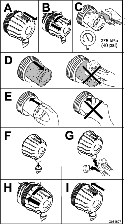
Servicing the Air Cleaner
Note: If the foam gasket in the cover is damaged, replace it.
Important: Avoid using high-pressure air, which could force dirt through the filter into the intake tract.
Important: Do not clean the used filter to avoid damaging the filter media.
Important: Do not use a damaged filter.
Important: Do not apply pressure to the flexible center of the filter.
Servicing the Engine Oil
| Maintenance Service Interval | Maintenance Procedure |
|---|---|
| After the first 50 hours |
|
| Before each use or daily |
|
| Every 250 hours |
|
Engine-Oil Specifications
The engine ships with oil in the crankcase; however, check the oil level before and after you first start the engine.
Crankcase capacity: 5.2 L (5.5 US Qt) with the filter
Preferred engine oil: Toro Premium Engine Oil
If using an alternate oil, use high-quality, low-ash engine oil that meets or exceeds the following specifications:
-
API service category CJ-4 or higher
-
ACEA service category E6
-
JASO service category DH-2
Important: Using engine oil other than API classification CJ-4 or higher, ACEA E6, or JASO DH-2 may cause the diesel particulate filter to plug or cause engine damage.
Use the following engine oil viscosity grade:
-
SAE 10W-30 or 5W-30 (all temperatures)
-
SAE 15W-40 (above 0° F)
Note: Toro Premium Engine oil is available from your Authorized Service Dealer.
Checking the Engine-Oil Level
-
Park the machine on a level surface, engage the parking brake, and lower the loader arms.
-
Shut off the engine, remove the key, and allow the engine to cool.
-
Open the hood.
-
Remove the left side screen.
-
Clean the area around the oil dipstick and oil-fill cap.
-
Check the oil and add additional oil as needed.
Important: Do not overfill the crankcase with oil; if the oil in the crankcase is too high and you run the engine, you may damage the engine.
-
Close the hood.
Changing the Engine Oil and Filter
-
Remove any attachments.
-
Start the engine and let it run for 5 minutes.
Note: This warms the oil so that it drains better.
-
Park the machine on a level surface and engage the parking brake.
-
Raise the loader arms and install the cylinder locks.
-
Shut off the engine and remove the key.
-
Drain the oil beneath the platform.
Caution
Components will be hot if the machine has been running. If you touch hot components, you may be burned.
Use care to avoid touching hot components while changing the oil and/or filter.
-
Torque the drain plug to 46 to 56 N∙m (34 to 42 ft-lb).
-
Open the hood.
-
Remove the left screen; refer to Removing the Side Screens.
-
Place a shallow pan or rag under the filter to catch oil.
-
Change the oil filter.
-
Remove the oil-fill cap and slowly pour approximately 80% of the specified amount of oil in through the valve cover.
-
Check the oil level.
-
Slowly add additional oil to bring the level to the upper hole on the dipstick.
-
Replace the fill cap.
-
Install the left screen.
-
Close the hood.
Servicing the Diesel-Oxidation Catalyst (DOC) and the Soot Filter
| Maintenance Service Interval | Maintenance Procedure |
|---|---|
| Every 3,000 hours |
|
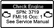
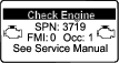
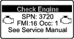
If engine faults , , or display in the InfoCenter, clean the soot filter using the steps that follow:
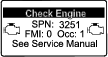
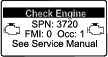
-
Refer to the Engine section in the Service Manual for information on disassembling and assembling the diesel-oxidation catalyst and the soot filter of the DPF.
-
Refer to your Authorized Service Dealer for diesel-oxidation catalyst and the soot filter replacement parts or service.
-
Contact your Authorized Service Dealer to reset the engine ECU after you install a clean DPF.
Fuel System Maintenance
Danger
In certain conditions, fuel is extremely flammable and highly explosive. A fire or explosion from fuel can burn you and others and can damage property.
Refer to Fuel Safety for a complete list of fuel related precautions.
Draining the Water Separator
| Maintenance Service Interval | Maintenance Procedure |
|---|---|
| Every 50 hours |
|
-
Park the machine on a level surface, engage the parking brake, and lower the loader arms.
-
Shut off the engine and remove the key.
-
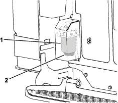
Place a container under the water separator.
-
Loosen the drain valve on the bottom of the filter canister and allow the water to drain.
-
Tighten the drain valve.
Replacing the Water Separator Filter
| Maintenance Service Interval | Maintenance Procedure |
|---|---|
| Every 500 hours |
|
-
Park the machine on a level surface, engage the parking brake, and lower the loader arms.
-
Shut off the engine and remove the key.
-
Remove the rear cover; refer to Removing the Rear Cover.
-
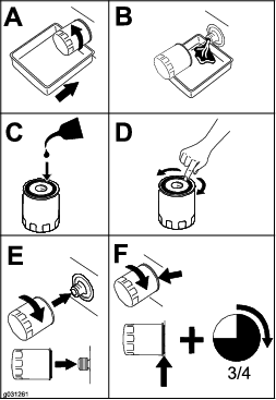
Clean the area where the water separator filter mounts.
-
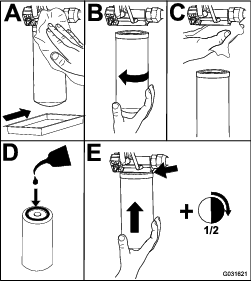
Remove the filter canister and clean the mounting surface
-
Lubricate the gasket on the new filter canister with clean oil.
-
Fill the canister with fuel.
-
Install the filter canister by hand until the gasket contacts the mounting surface, then rotate it an additional 1/2 turn.
-
Install the rear cover.
Checking the Fuel Lines and Connections
| Maintenance Service Interval | Maintenance Procedure |
|---|---|
| Every 400 hours |
|
Inspect the fuel lines and connections for deterioration, damage, or loose connections. Tighten any loose connections and contact your Authorized Service Dealer for assistance in fixing damaged fuel lines.
Replacing the Fuel Filter
| Maintenance Service Interval | Maintenance Procedure |
|---|---|
| Every 500 hours |
|
-
Park the machine on a level surface, engage the parking brake, and lower the loader arms.
-
Shut off the engine and remove the key.
-
Open the hood.
-
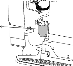
Clean the area where the fuel filter mounts.
-
Remove the filter canister and clean the mounting surface.
-
Lubricate the gasket on the new filter canister with clean oil.
-
Install the filter canister by hand until the gasket contacts the mounting surface, then rotate it an additional 1/2 turn.
-
Bleed the fuel system; refer to Bleeding the Fuel System.
-
Start the engine and check for fuel leaks around the filter head.
-
Close the hood.
Bleeding the Fuel System
You must bleed the fuel system before starting the engine if any of the following situations have occurred:
-
Initial startup of a new machine
-
The engine has ceased running due to a lack of fuel.
-
Maintenance has been performed upon fuel-system components (e.g., filter replaced).
-
Turn the key to the RUN position.
-
Let the fuel pump run for 2 minutes prior to starting the machine.
Draining the Fuel Tank(s)
| Maintenance Service Interval | Maintenance Procedure |
|---|---|
| Every 500 hours |
|
Have an Authorized Service Dealer drain and clean the fuel tank(s).
Electrical System Maintenance
Electrical System Safety
-
Disconnect the battery before making any repairs; refer to Using the Battery-Disconnect Switch.
-
Charge the battery in an open, well-ventilated area, away from sparks and flames. Unplug the charger before connecting or disconnecting the battery. Wear protective clothing and use insulated tools.
-
Battery acid is poisonous and can cause burns. Avoid contact with skin, eyes, and clothing. Protect your face, eyes, and clothing when working with a battery.
-
Battery gases can explode. Keep cigarettes, sparks, and flames away from the battery.
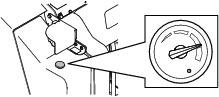
Using the Battery-Disconnect Switch
-
Park the machine on a level surface, engage the parking brake, and lower the loader arms.
-
Shut off the engine and remove the key.
-
Open the hood.
-
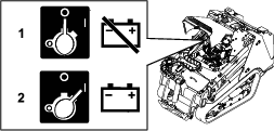
Turn the battery-disconnect switch to the ON or OFF position to perform the following:
-
To energize the machine electrically, rotate the battery-disconnect switch clockwise to the ON position.
-
To de-energize the machine electrically, rotate the battery-disconnect switch counterclockwise to the OFF position.
-
Servicing the Battery
| Maintenance Service Interval | Maintenance Procedure |
|---|---|
| Every 50 hours |
|
Removing the Battery
Warning
Incorrect battery cable routing could damage the machine and cables, causing sparks. Sparks can cause the battery gasses to explode, resulting in personal injury.
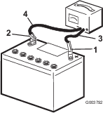
Always disconnect the negative (black) battery cable before disconnecting the positive (red) cable.
-
Remove any attachments.
-
Park the machine on a level surface and engage the parking brake.
-
Raise the loader arms and install the cylinder locks.
-
Shut off the engine and remove the key.
-
Remove the front cover assembly; refer to Removing the Front Cover Assembly.
-
Disconnect the negative (black) ground cable from the battery post. Retain the fasteners.
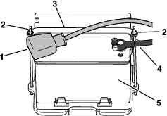
-
Slide the rubber cover off the positive (red) cable.
-
Disconnect the positive (red) cable from the battery post. Retain the fasteners.
-
Remove the wing nuts, rods, and strap.
-
Remove the battery.
Charging the Battery
Warning
Charging the battery produces gasses that can explode.
Never smoke near the battery and keep sparks and flames away from battery.
Important: Always keep the battery fully charged (1.265 specific gravity). This is especially important to prevent battery damage when the temperature is below 0°C (32°F).
-
Remove the battery from the machine; refer to Removing the Battery.
-
Charge the battery for 4 to 8 hours at a rate of 3 to 4 A. Do not overcharge the battery.
-
When the battery is fully charged, unplug the charger from the electrical outlet, then disconnect the charger leads from the battery posts.
Cleaning the Battery
Note: Keep the terminals and the entire battery case clean, because a dirty battery discharges slowly.
-
Park the machine on a level surface, engage the parking brake (if equipped), and lower the loader arms.
-
Shut off the engine and remove the key.
-
Remove the battery from the machine; Removing the Battery.
-
Wash the entire case with a solution of baking soda and water.
-
Rinse the battery with clear water.
-
Coat the battery posts and cable connectors with Grafo 112X (skin-over) grease (Toro Part No. 505-47) or petroleum jelly to prevent corrosion.
-
Install the battery; refer to Installing the Battery.
Installing the Battery
Warning
Incorrect battery cable routing could damage the machine and cables, causing sparks. Sparks can cause the battery gasses to explode, resulting in personal injury.
Always connect the positive (red) battery cable before connecting the negative (black) cable.
-
Place the battery on the battery tray and secure it with the strap, wing nuts, and rods.
-
Using the fasteners previously removed, install the positive (red) battery cable to the positive (+) battery terminal.
-
Slide the red terminal boot onto the positive battery post.
-
Using the fasteners previously removed, install the negative (black) battery cable to the negative (-) battery terminal.
-
Install the front cover assembly.
Servicing a Replacement Battery
The original battery is maintenance-free and does not require service. For servicing a replacement battery, refer to the battery manufacturer’s instructions.
Jump-Starting the Machine
Warning
Jump-starting the battery can produce gasses that can explode.
Do not smoke near the battery, and keep sparks and flames away from battery.
-
Remove the front cover; refer to Removing the Front Cover.
-
Check and clean corrosion from the battery terminals before jump-starting. Ensure that the connections are tight.
Caution
Corrosion or loose connections can cause unwanted electrical voltage spikes at any time during the jump-starting procedure.
Do not attempt to jump-start the machine with loose or corroded battery terminals, or damage to the engine may occur.
Danger
Jump-starting a weak battery that is cracked or frozen or has a low electrolyte level or an open/shorted battery cell can cause an explosion, resulting in serious personal injury.
Do not jump-start a weak battery if these conditions exist.
-
Make sure that the booster battery is a good and fully charged lead-acid battery at 12.6 V or greater.
Note: Use properly sized jumper cables with short lengths to reduce voltage drop between systems. Make sure that the cables are color coded or labeled for the correct polarity.
Warning
Batteries contain acid and produce explosive gases.
-
Shield your eyes and face from the batteries at all times.
-
Do not lean over the batteries.
Note: Ensure that the vent caps are tight and level. Place a damp cloth, if available, over any vent caps on both batteries. Also ensure that the machines do not touch and that both electrical systems are off and at the same rated system voltage. These instructions are for negative ground systems only.
-
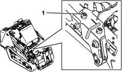
-
Connect the positive (+) cable to the positive (+) terminal of the discharged battery that is wired to the starter or solenoid as shown in Figure 82.
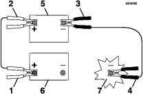
-
Connect the other end of the positive (+) jumper cable to the positive terminal of the battery in the other machine.
-
Connect an end of the negative (-) jumper cable to the negative post of the battery in the other machine.
-
Connect the other end of the negative (-) jumper cable to a ground point, such as an unpainted bolt or chassis member.
-
Start the engine in the other machine. Let it run a few minutes, then start your engine.
-
Remove the cables in the reverse order of connection.
-
Install the front cover.
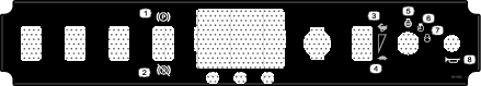
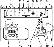
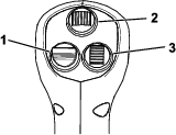
Servicing the Fuses
The electrical system is protected by fuses. It requires no maintenance; however, if a fuse blows, check the component/circuit for a malfunction or a short.
| 1 | 2 | 3 | 4 | 5 | 6 | 7 | 8 | 9 | 10 | 11 | 12 | |
| A | X | X | Joystick | Attachment Power | Accessory | Tec Power | Horn | |||||
| (5 A) | (20 A) | (10 A) | (7.5 A) | (10 A) | ||||||||
| B | X | X | X | X | TDM 2002 | Auto Level | Tec Power | Lights/USB | ||||
| (10 A) | (10 A) | (7.5 A) | (15 A) | |||||||||
| C | X | X | X | X | Telematics | X | X | Tec Power | System Power | |||
| (10 A) | (7.5 A) | (15 A) | ||||||||||
| D | X | X | X | (Relay) | (Relay) | (Relay) | ||||||
| E | X | X | X | |||||||||
Note: If the machine does not start, either the main circuit or the control panel/relay fuse could be blown.
Drive System Maintenance
Servicing the Tracks
| Maintenance Service Interval | Maintenance Procedure |
|---|---|
| After the first 8 hours |
|
| After the first 50 hours |
|
| Before each use or daily |
|
| Every 50 hours |
|
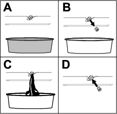
Cleaning the Tracks
-
Park the machine on a level surface and engage the parking brake.
-
With the bucket installed and angled downward, lower it into the ground so that the front of the traction unit lifts off the ground a few centimeters (inches).
-
Shut off the engine and remove the key.
-
Using a water hose or pressure washer, remove dirt from each track system.
Important: Ensure that you use high-pressure water to wash only the track area. Do not use a high-pressure washer to clean the rest of the traction unit. Do not use high pressure water between the drive sprocket and the traction unit or you may damage the motor seals. High-pressure washing can damage the electrical system and hydraulic valves or deplete grease.
Important: Ensure that you fully clean the road wheels, front wheel, rear wheel, and drive sprocket. The road wheels should rotate freely when clean.
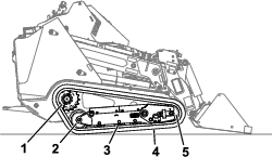
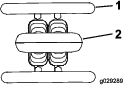
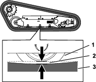
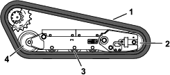
Checking and Adjusting the Track Tension
Lift/support 1 side of the machine and using the weight of the track, verify that the gap between the bottom of the lip of the road wheel and the track is 19 mm (3/4 inch). If it is not, adjust the track tension using the following procedure.
-
Park the machine on a level surface, engage the parking brake, and lower the loader arms.
-
Shut off the engine and remove the key.
-
Raise the side of the machine that you are adjusting so that the track is off the ground.
-
Loosen the bolts on the rear cover and remove the cover.
-
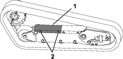
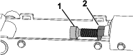
Loosen the jam nut and turn the tensioning screw clockwise until the track deflection is 19 mm (3/4 inch).
-
Tighten the jam nut.
-
Install the cover and tighten the bolts.
-
Repeat the procedure for the other track.
-
Drive the machine, then park the machine on a level surface, engage the parking brake, shut off the engine, and remove the key.
-
Verify that the track deflection is 19 mm (3/4 inch). Adjust if necessary.
Replacing the Tracks
Removing the Tracks
-
Remove any attachments.
-
Park the machine on a level surface, ensuring that only 1 sprocket half is engaged with the track.
-
Lower the loader arms.
-
Shut off the engine and remove the key.
-
Raise the machine off the ground so that the bottom of the track is at least 10.2 cm (4 inches) off the ground. Support the machine using jack stands.
Note: Use jack stands rated for your machine.
Warning
Mechanical or hydraulic jacks may fail to support the machine and cause serious injury.
Use jack stands when supporting the machine.
-
Loosen the bolts on the rear cover and remove the cover.
-
Loosen the jam nut and turn the tensioning screw to release the tension.
-
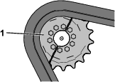
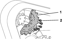
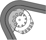
Remove the segment of the drive sprocket not engaged with the track.
Important: If you do not remove the sprocket segment, it may be difficult to install a new track without damaging it.
-
Start the machine and disengage the parking brake.
-
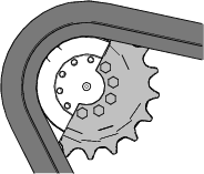
Move the traction control forward until the other half of the drive sprocket is not engaged with the track
-
Shut off the engine and remove the key.
-
Remove the track from the track frame, drive hub, then front wheel.
Installing the Tracks
-
Wrap the new track around the front wheel.
-
Push the track under and between the road wheels and wrap it around the rear wheel.
-
Start the engine and disengage the parking brake.
-
Move the traction control forward until the drive sprocket half engages with the track.
-
Shut off the engine and remove the key.
-
Apply thread-locking compound to the bolts of the drive sprocket half that you removed and install the other sprocket half. Torque the bolts to 80 to 99 N∙m (59 to 73 ft-lb).
-
Adjust the tensioning screw until the track deflection is 19 mm (3/4 inch).
-
Tighten the jam nut.
-
Install the cover and tighten the bolts.
-
Repeat the procedure to replace the other track.
-
Lower the machine to the ground.
-
Drive the machine, then park the machine on a level surface, engage the parking brake, shut off the engine, and remove the key.
-
Verify that the track tension is correct; refer to Checking and Adjusting the Track Tension.
Cooling System Maintenance
Cooling System Safety
-
Swallowing engine coolant can cause poisoning; keep out of reach from children and pets.
-
Discharge of hot, pressurized coolant or touching a hot radiator and surrounding parts can cause severe burns.
-
Always allow the engine to cool at least 15 minutes before removing the radiator cap.
-
Use a rag when opening the radiator cap, and open the cap slowly to allow steam to escape.
-
Servicing the Cooling System
| Maintenance Service Interval | Maintenance Procedure |
|---|---|
| Before each use or daily |
|
| Every 100 hours |
|
Cleaning the Radiator Screen
| Maintenance Service Interval | Maintenance Procedure |
|---|---|
| Before each use or daily |
|
Remove any buildup of grass, dirt or other debris from the radiator screen with compressed air.
Checking the Engine-Coolant Level
| Maintenance Service Interval | Maintenance Procedure |
|---|---|
| Before each use or daily |
|
The cooling system is filled with a 50/50 solution of water and permanent ethylene-glycol antifreeze.
-
Park the machine on a level surface, lower the loader arms, engage the parking brake, and shut off the engine.
-
Remove the key from the key switch and allow the engine to cool.
-
Open the hood.
-
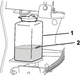
Check the coolant level in the expansion tank.
Note: The coolant level should be at or above the mark on the side of the tank.
-
If the coolant level is low, remove the expansion tank cap and add a 50/50 mixture of water and permanent ethylene-glycol antifreeze.
Important: Do not overfill the expansion tank.
-
Install the expansion-tank cap.
Changing the Engine Coolant
| Maintenance Service Interval | Maintenance Procedure |
|---|---|
| Every 800 hours |
|
Have an Authorized Service Dealer change the engine coolant yearly.
If you need to add engine coolant, refer to Checking the Engine-Coolant Level.
Belt Maintenance
Checking the Alternator-Belt Tension
| Maintenance Service Interval | Maintenance Procedure |
|---|---|
| Every 100 hours |
|
-
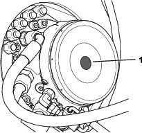
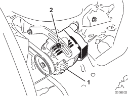
Apply 44 N (10 lb) of force to the alternator belt, midway between the pulleys.
-
If the deflection is not 10 mm (3/8 inch), loosen the alternator mounting bolts.
-
Increase or decrease the alternator-belt tension.
-
Tighten the mounting bolts.
-
Check the deflection of the belt again to ensure that the tension is correct.
Controls System Maintenance
Adjusting the Controls
The factory adjusts the controls before shipping the machine. However, after many hours of use, you may need to adjust the traction control alignment, the NEUTRAL position of the traction control, and the tracking of the traction control in the full forward position.
Contact your Authorized Service Dealer to adjust the controls of your machine.
Hydraulic System Maintenance
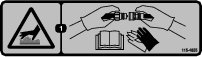
Hydraulic System Safety
-
Seek immediate medical attention if fluid is injected into skin. Injected fluid must be surgically removed within a few hours by a doctor.
-
Ensure that all hydraulic-fluid hoses and lines are in good condition and all hydraulic connections and fittings are tight before applying pressure to the hydraulic system.
-
Keep your body and hands away from pinhole leaks or nozzles that eject high-pressure hydraulic fluid.
-
Use cardboard or paper to find hydraulic leaks.
-
Safely relieve all pressure in the hydraulic system before performing any work on the hydraulic system.
Relieving Hydraulic Pressure
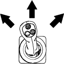
To relieve hydraulic pressure while the engine is on, disengage the auxiliary hydraulics and fully lower and retract the loader arms.
To relieve the pressure while the engine is off, cycle the joystick between the forward positions to lower the loader arms.
Hydraulic Fluid Specifications
| Maintenance Service Interval | Maintenance Procedure |
|---|---|
| Every 100 hours |
|
| Every 400 hours |
|
| Every 1,000 hours |
|
| Every 1,500 hours |
|
| Every 2 years |
|
Hydraulic-Tank Capacity: 44.7 L (11.8 US gallons)
Use only 1 of the following fluids in the hydraulic system:
-
Toro Premium Transmission/Hydraulic Tractor Fluid (refer to your Authorized Service Dealer for more information)
-
Toro PX Extended Life Hydraulic Fluid (refer to your Authorized Service Dealer for more information)
-
If either of the above Toro fluids are not available, you may use another Universal Tractor Hydraulic Fluid (UTHF), but they must be only conventional, petroleum-based products. The specifications must fall within the listed range for all the following material properties and the fluid should meet the listed industry standards. Check with your hydraulic fluid supplier to determine if the fluid meets these specifications.
Note: Toro will not assume responsibility for damage caused by improper substitutions, so use only products from reputable manufacturers who will stand behind their recommendations.
Material Properties Viscosity, ASTM D445 cSt at 40°C: 55 to 62 cSt at 100°C: 9.1 to 9.8 Viscosity index, ASTM D2270 140 to 152 Pour Point, ASTM D97 -37 to -43°C (-35 to -46°F) Industry Standards API GL-4, AGCO Powerfluid 821 XL, Ford New Holland FNHA-2-C-201.00, Kubota UDT, John Deere J20C, Vickers 35VQ25 and Volvo WB-101/BM Note: Many hydraulic fluids are almost colorless, making it difficult to spot leaks. A red dye additive for the hydraulic system fluid is available in 20 ml (2/3 fl oz) bottles. One bottle is sufficient for 15 to 22 L (4 to 6 US gallons) of hydraulic fluid. Order Part No. 44-2500 from your Authorized Toro Dealer.
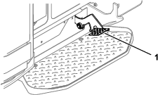
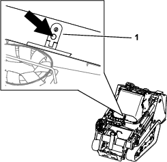
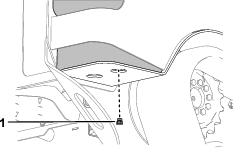
Checking the Hydraulic-Fluid Level
| Maintenance Service Interval | Maintenance Procedure |
|---|---|
| Every 25 hours |
|
Important: Always use the correct hydraulic fluid. Unspecified fluids will damage the hydraulic system. Refer to Hydraulic Fluid Specifications.
-
Remove any attachments.
-
Park the machine on a level surface and engage the parking brake.
-
Shut off the engine and remove the key.
-
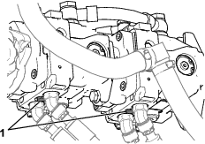
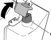
Raise the bracket.
-
Clean the area around the filler cap .
-
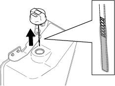
Remove the filler-neck cap and check the fluid level on the dipstick.
Note: The fluid level should be within the marks on the dipstick.
-
If the level is low, add enough fluid to raise it to the proper level.
-
Install the filler cap.
-
Lower the bracket.
Replacing the Hydraulic Filters
Important: Do not substitute an automotive oil filter; otherwise, severe hydraulic system damage may occur.
-
Remove any attachments.
-
Park the machine on a level surface and engage the parking brake.
-
Raise the loader arms and install the cylinder locks.
-
Shut off the engine, remove the key, and allow the engine to cool.
-
Remove the front cover; refer to Removing the Front Cover.
-
Place a drain pan under the filter and replace the filter.
-
Clean up any spilled fluid.
-
Start the engine and let it run for about 2 minutes to purge air from the system.
-
Shut off the engine and check for leaks.
-
Check the fluid level in the hydraulic tank; refer toChecking the Hydraulic-Fluid Level and add fluid to raise the level to mark on dipstick.
Important: Do not overfill the tank.
-
Install the front cover.
-
Remove and store the cylinder locks and lower the loader arms.
Changing the Hydraulic Fluid
-
Park the machine on a level surface, engage the parking brake, and lower the loader arms.
-
Shut off the engine and remove the key.
-
Place a large drain pain capable of holding 57 L (15 US gallons) under the drain plug on the hydraulic tank.
-
Remove the drain plug and allow the oil to drain into the pan.
-
When the oil is finished draining, install and tighten the drain plug.
Note: Dispose of the used oil at a certified recycling center.
-
Fill the hydraulic tank with hydraulic fluid; refer to Hydraulic Fluid Specifications.
-
Start the engine and let it run for a few minutes.
-
Shut off the engine and remove the key.
-
Check the hydraulic-fluid level and add fluid to fill the tank if necessary; refer to Checking the Hydraulic-Fluid Level.
Loader Maintenance
Torquing the Loader Arm Adjustment Screws
| Maintenance Service Interval | Maintenance Procedure |
|---|---|
| Every 25 hours |
|
Check the torque whenever the lower loader arms rattle.
-
Park the machine on a level surface.
-
Shut off the engine, remove the key, and allow the engine to cool.
-
On each loader arm, loosen the setscrew on the 4 adjustment screws.
-
Torque the adjustment screws to 27 N∙m (20 ft-lb).
-
Check that the length of the adjustment screws that is protruding from the arms is equal side to side.
-
Apply medium-strength thread-locking compound to the setscrews and tighten them until they just contact the adjustment screws.
Important: Do not overtighten the setscrews; otherwise you may damage the adjustment screw threads.
Cleaning
Removing Debris
| Maintenance Service Interval | Maintenance Procedure |
|---|---|
| Before each use or daily |
|
Important: Operating the engine with blocked screens and/or cooling shrouds removed will result in engine damage from overheating.
-
Park the machine on a level surface and lower the loader arms.
-
Shut off the engine, remove the key, and allow the engine to cool.
-
Open the hood.
-
Clean any debris from the front and side screens.
-
Wipe away debris from the air cleaner.
-
Clean any debris buildup on the engine and in the oil cooler fins with a brush or blower.
Important: Operating the engine with blocked screens and/or cooling shrouds removed will result in engine damage due to overheating.
-
Clean debris from the hood opening, muffler, heat shields, and radiator screen (if applicable).
-
Close the hood.
Washing the Machine
When pressure washing the machine, do the following:
-
Wear appropriate personal protective equipment for the pressure washer.
-
Keep all guards in place on the machine.
-
Avoid spraying at electronic components.
-
Avoid spraying at edges of decals.
-
Spray the exterior of the machine only. Do not spray directly into openings in the machine.
-
Spray only the dirty parts of the machine.
-
Use a 40-degree or larger spray nozzle. 40-degree nozzles are usually white.
-
Keep the tip of the pressure washer at least 61 cm (2 ft) away from the surface being washed.
-
Use only pressure washers with pressure below 13790 kpa (2000 psi) and flow below 7.6 L (2 US gallons) per minute.
-
Replace damaged or peeling decals.
-
Grease all grease points after washing; refer to Greasing the Machine.
Cleaning the Chassis
| Maintenance Service Interval | Maintenance Procedure |
|---|---|
| Every 100 hours |
|
Over time, the chassis under the engine collects dirt and debris that must be removed. Using a flashlight, open the hood and inspect the area under the engine regularly. When the debris is 2.5 to 5 cm (1 to 2 inches) deep, clean the chassis.
-
Park the machine on a level surface and lower the loader arms.
-
Raise the front of the machine so that the machine is angled backward.
-
Shut off the engine and remove the key.
-
Remove the bottom plate; refer to Removing the Bottom Plate.
-
Remove the front cover assembly; refer to Removing the Front Cover Assembly.
-
Spray water into the chassis to clean out the dirt and debris.
Note: The water will drain at the back of the machine.
Important: Do not spray water into the engine.
-
Grease the machine; refer to Greasing the Machine.
-
Install the bottom plate.
-
Install the front cover assembly.
-
Lower the machine.