Maintenance
-
Replace all worn or damaged parts with genuine Toro parts.
-
Periodically check that all lights are working.
-
Ensure that the headlights are adjusted correctly.
-
Clean the lights daily.
Schematic
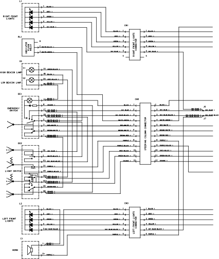
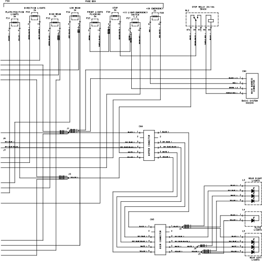
Park the machine on a level surface, engage the parking brake, lower the cutting unit, shut off the engine, and remove the key.
Disconnect the battery; refer to the electrical system maintenance section of your Operator’s Manual.
Using a drill without wearing eye protection may allow debris to enter the eye, causing personal injury.
When drilling, always wear eye protection.
Parts needed for this procedure:
| Rear taillight | 2 |
| Rear light plate | 1 |
| Set screw (M5 x 30 mm) | 4 |
| Washer (3/16 inch) | 4 |
| Locknut (M5) | 4 |
| Plate-number light | 1 |
| Screw | 2 |
| Washer | 2 |
| Nut | 2 |
| Hex-head bolt (M5 x 14 mm) | 5 |
| Washer | 5 |
| Washer | 7 |
| Nut | 7 |
| Hopper relfelector | 2 |
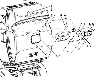
Install the 2 rear taillights to the rear light-plate with 4 set screws (M5 x 30 mm), 4 washers (3/16 inch), and 4 locknuts (M5); refer to Figure 1.
Install the plate-number light to the rear light plate with 2 screws, 2 washers, and 2 nuts.
Route the plate-number light connector behind the rear light plate.
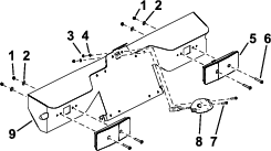
Using the rear light plate as a template, mark and drill 5 mm holes into the rear hopper door (Figure 2).
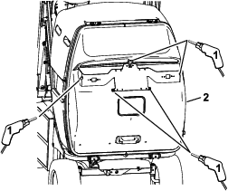
Loosely install the rear light plate to the hopper door with 5 hex-head bolts (M5 x 14 mm), 5 washers, and 5 nuts (Figure 3).
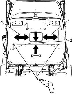
Using Figure 4, measure and mark the location for drilling the hopper reflector holes.
Drill a hole (5 mm) at each location (Figure 4).
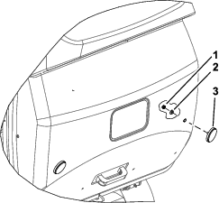
Install the reflectors to the hopper door with 2 washers and 2 nuts (Figure 5).
Parts needed for this procedure:
| Mirror | 2 |
| Left light arm | 1 |
| Right light arm | 1 |
| Left light assembly | 1 |
| Right light assembly | 1 |
| Horn | 1 |
| Nut | 3 |
| Screw | 3 |
| Washer (M8) | 3 |
| Screw | 2 |
| Washer | 2 |
Note: Ensure you have the spacers from the machine light kits or order the spacers (Part No. 134-8015).
Install the left light arm to the machine platform with 2 screws, 2 washers (M8), and 2 nuts (Figure 6).
Install the horn to the left light arm with a screw, washer (M8), and nut (Figure 6).
Install the left light marked “LH” to the left light arm with the screw, washer, and nut supplied with the light.
Install the mirror to the left light arm with 2 screws and 2 washers (Figure 6).
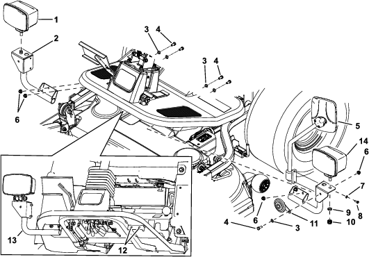
Install the right light arm to the machine platform with 2 screws, 2 washers (M8), and 2 nuts (Figure 6).
Install the right light marked “RH” to the right light arm with the screw, washer, and nut supplied with the light.
Install the mirror to the right light arm with 2 screws and 2 washers (Figure 6).
Note: Ensure both Headlights are pointing straight forward.
Parts needed for this procedure:
| Control cover | 1 |
| Console plate | 1 |
| Clamp | 1 |
| Hex-head screw | 2 |
| Relay | 1 |
| Console clamp | 1 |
| Washer | 1 |
| Nut | 1 |
| Multi-function switch | 1 |
| High/Low beam switch | 1 |
| Gasket | 1 |
| Hazard switch | 2 |
| Screw | 8 |
| Carriage bolt (M6 x 45 mm) | 4 |
| Clip (1/4-20) | 1 |
| Pan-head screw (M4 x 12 mm) | 3 |
| Switch support | 1 |
| Nut | 6 |
| Washer | 4 |
| Nut | 6 |
| Clamp | 1 |
| Washer | 4 |
| Hex-head bolt | 2 |
| Plastic rivet | 2 |
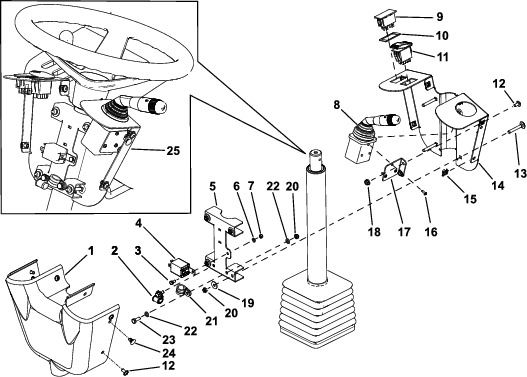
Install the 6 clips to the switch mount (Figure 7).
Install the multi-function switch to the switch support with 3 Pan-head screw (M4 x 12 mm) (Figure 7)
Install the switch support assembly to the console plate with 2 screws and 2 nuts.
Press the hazard switch into the console plate.
Intsall the gasket onto the high/low beam light switch and press the switch into the console plate.
Install the relay to the console clamp with a screw, washer, and nut.
Install the clamp to the console clamp with a screw, 2 wahsers, and a nut.
Install the clamp to the console clamp with a screw, 2 wahsers, and a nut (Figure 7).
Loosely install console plate around the steering column using the console clamp, 2 plastic rivets, 4 carriage bolts (M6 X 45 mm), 4 washers, and 4 nuts (Figure 7).
Parts needed for this procedure:
| Wire harness | 1 |
| Cable ties | 30 |
Refer to the following figures and instructions for routing the wire harness.
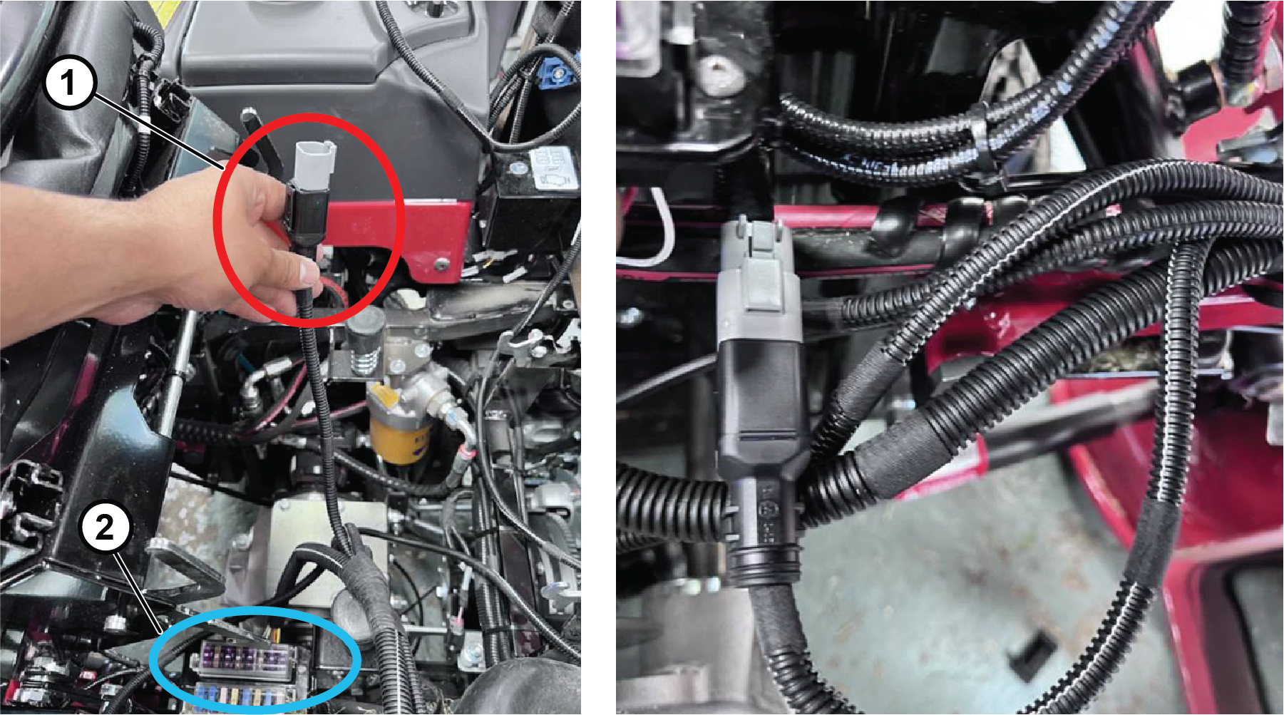
Connect the power adaptor to PLH600 machine wire harness below fuse box (Figure 8).
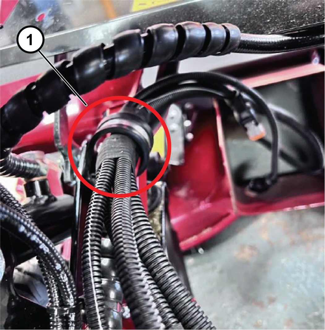
Feed the left and right front light wires and the console wires from road-light harness through the clamp (Figure 9).
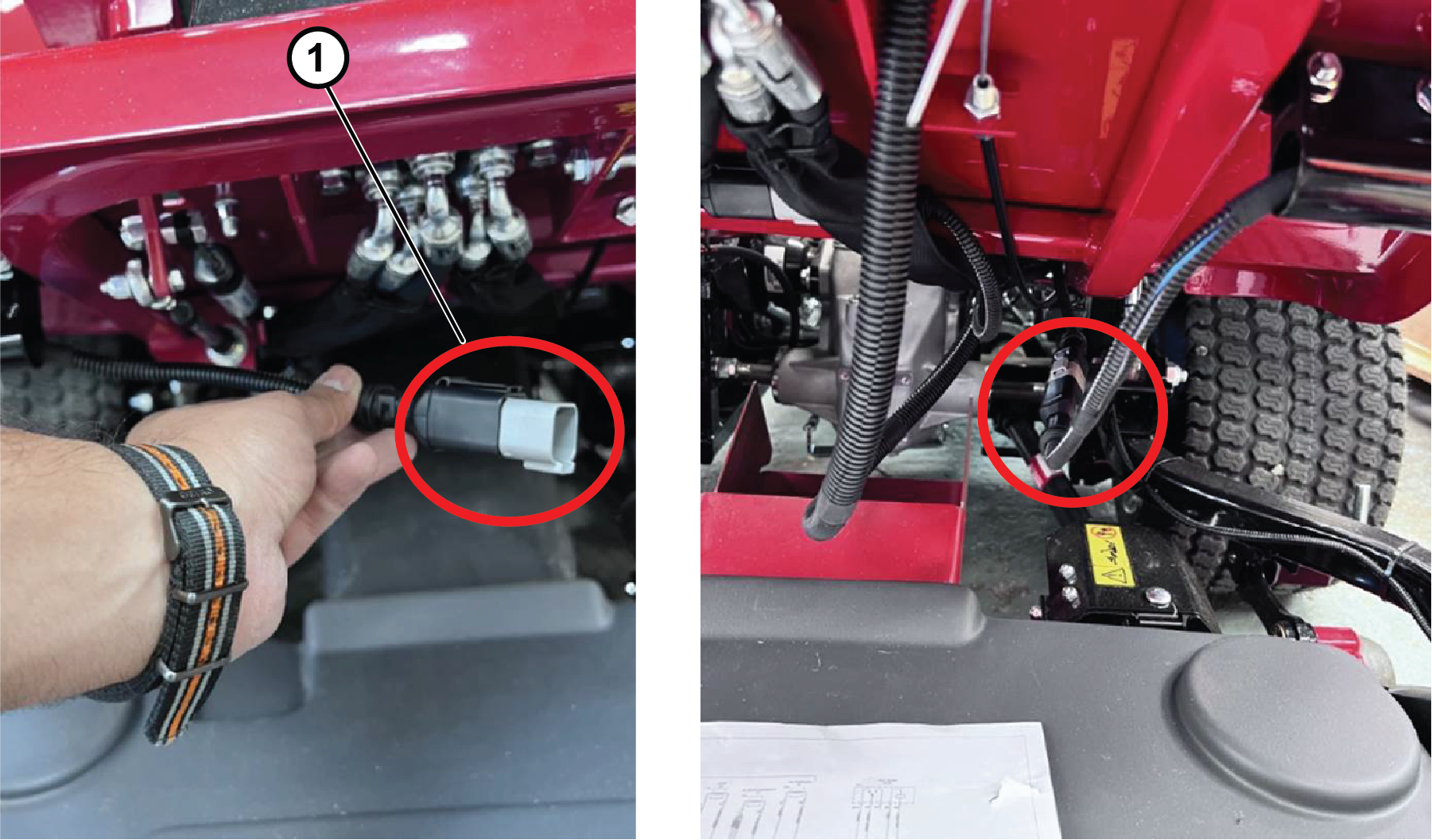
Connect road-light harness to the left and right front light connector. Secure the wires with cable ties to foot panel brace (Figure 10 and Figure 11).
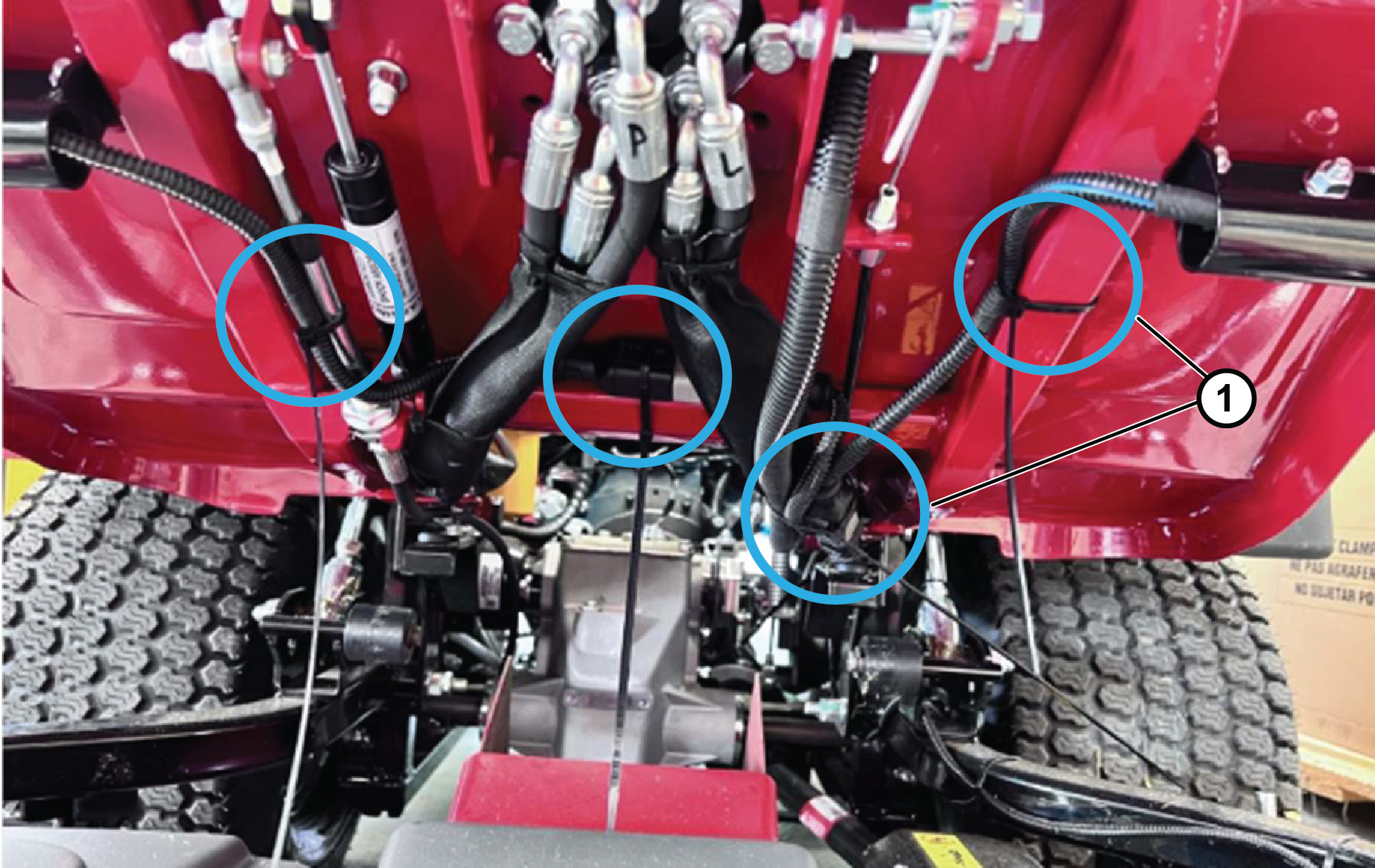
Feed the console wire from the road-light harness through platform and rear to the steering column (Figure 12).
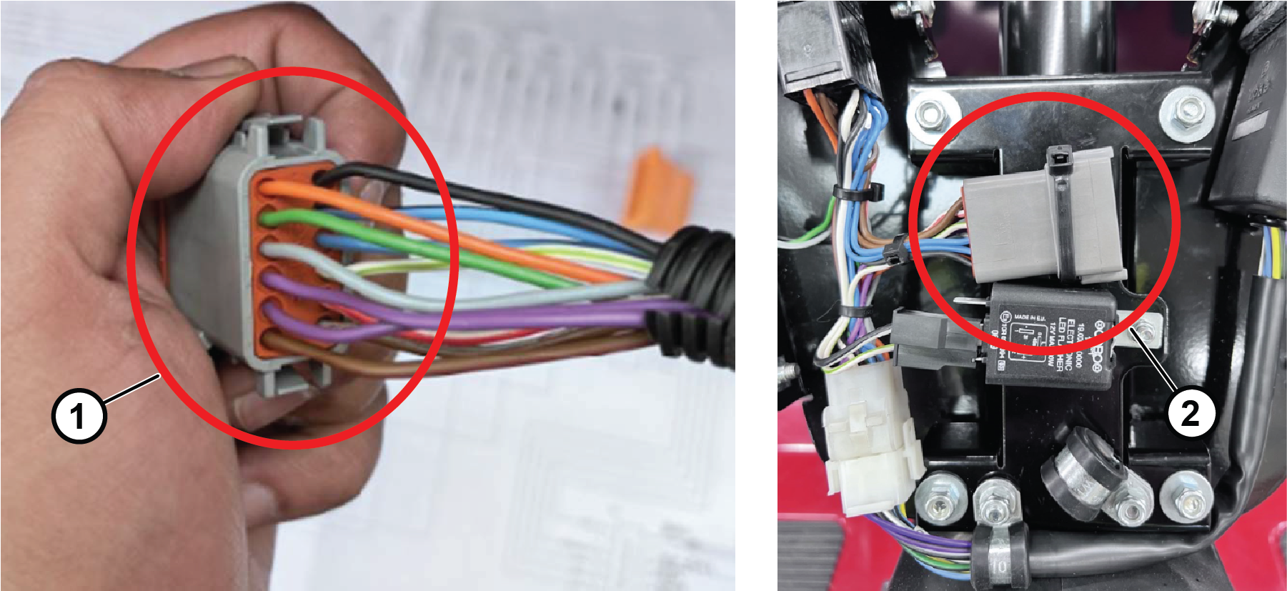
Connect the 12-way pin to console wire assembly (per electrical schematic) and connect it to the console assembly (Figure 13).
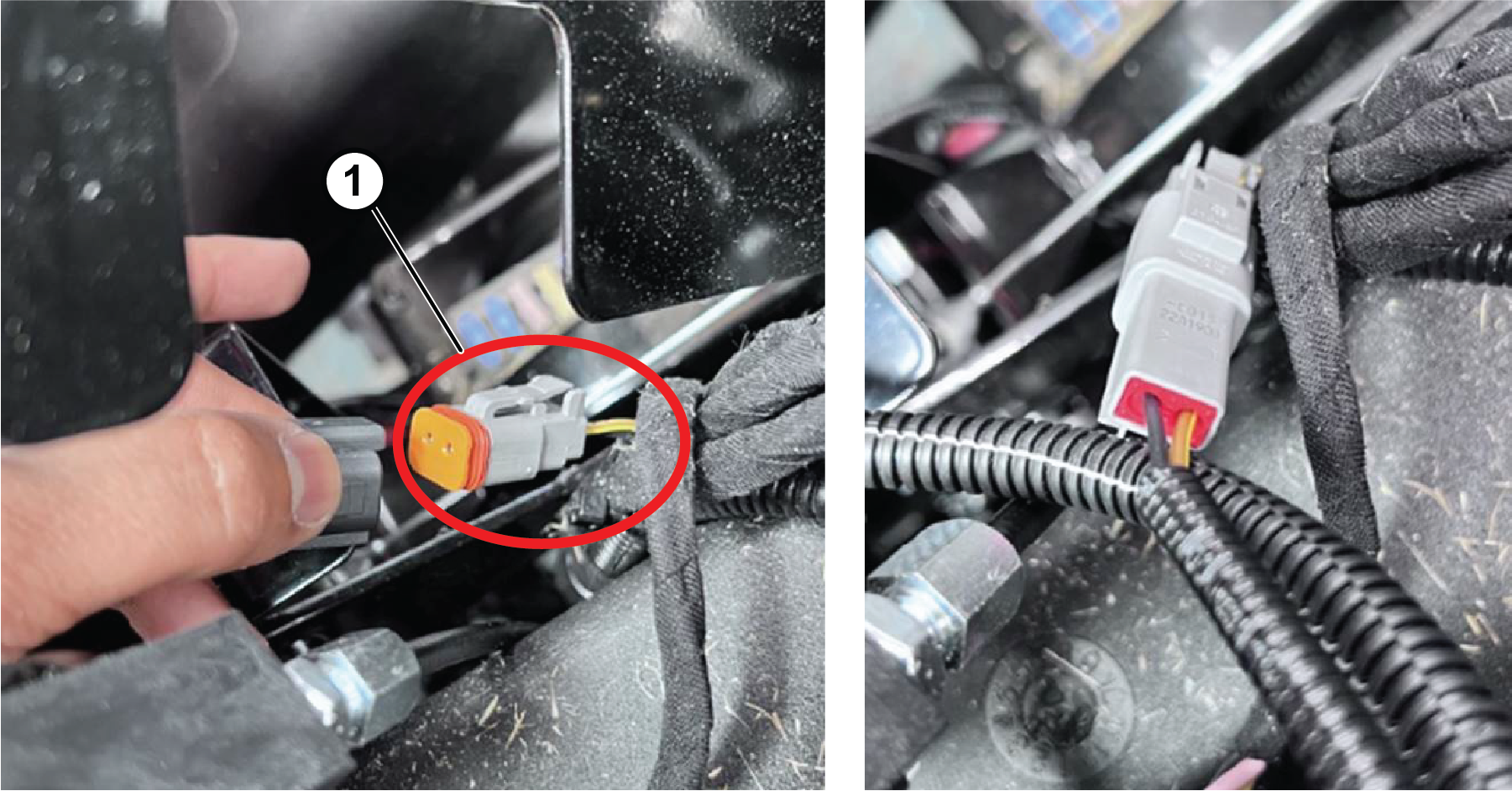
Connect the 2-way pin road-light wire harness to machine harness (Figure 14).
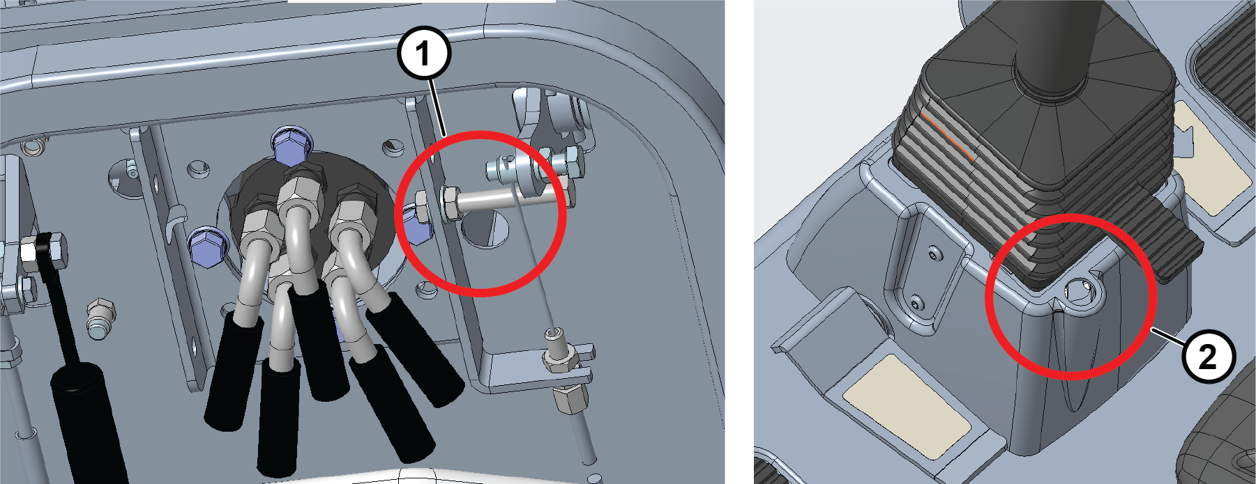
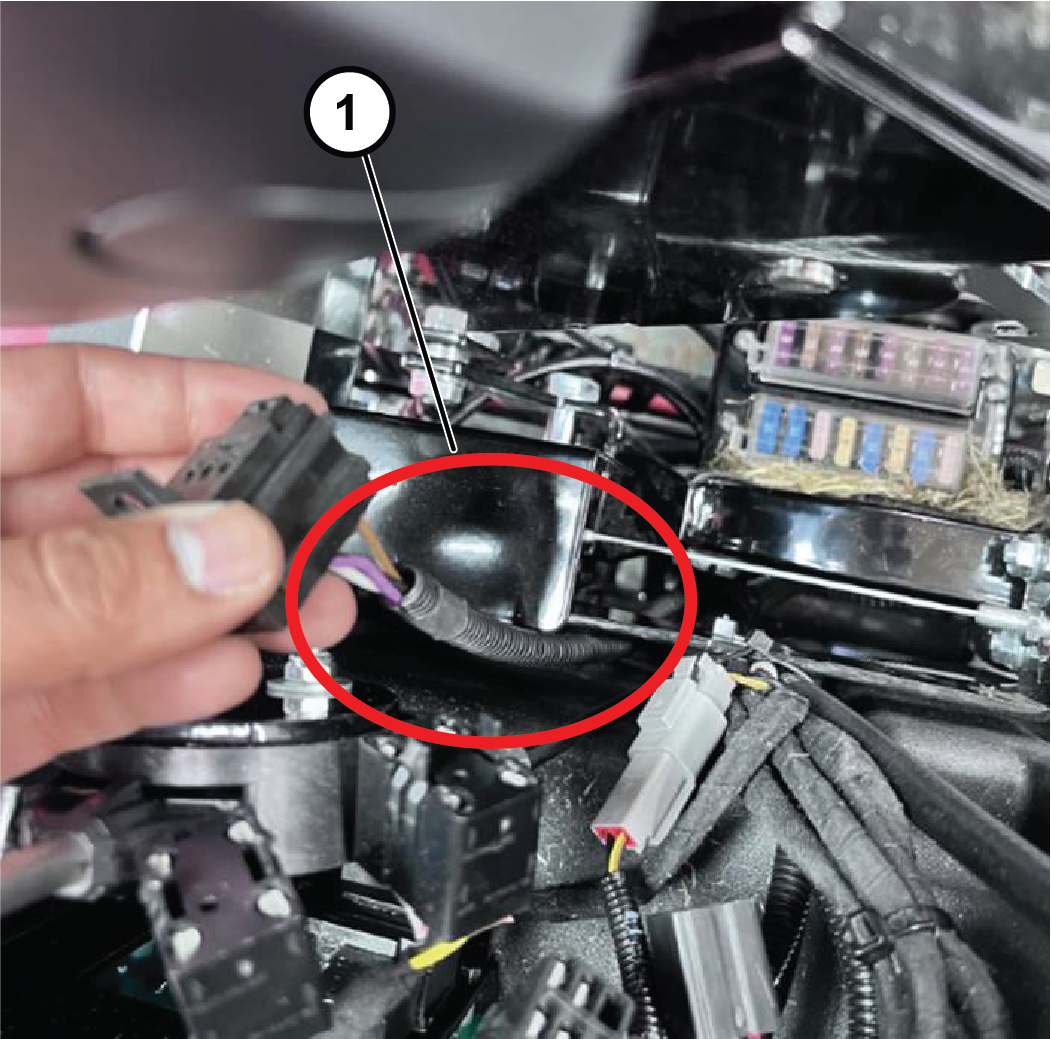
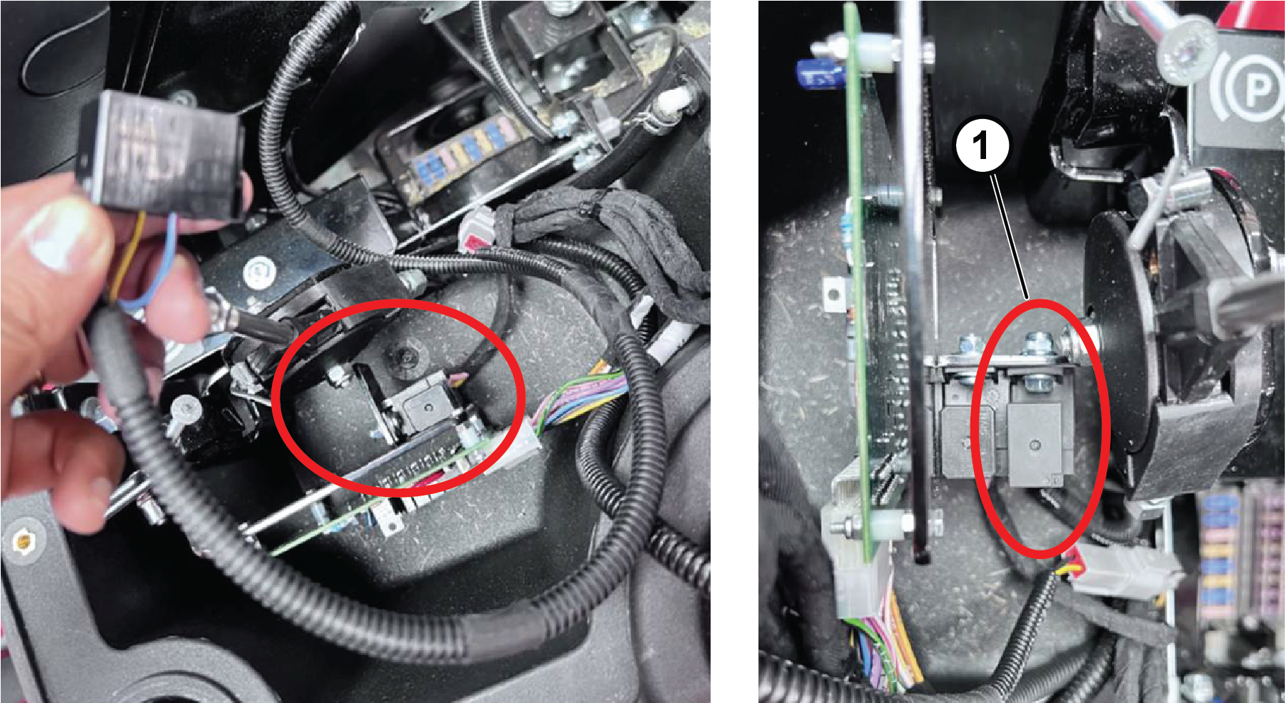
Feed the solenoid cable below the throttle assembly and fasten it to the bracket using a screw, washer, and a nut (Figure 15).
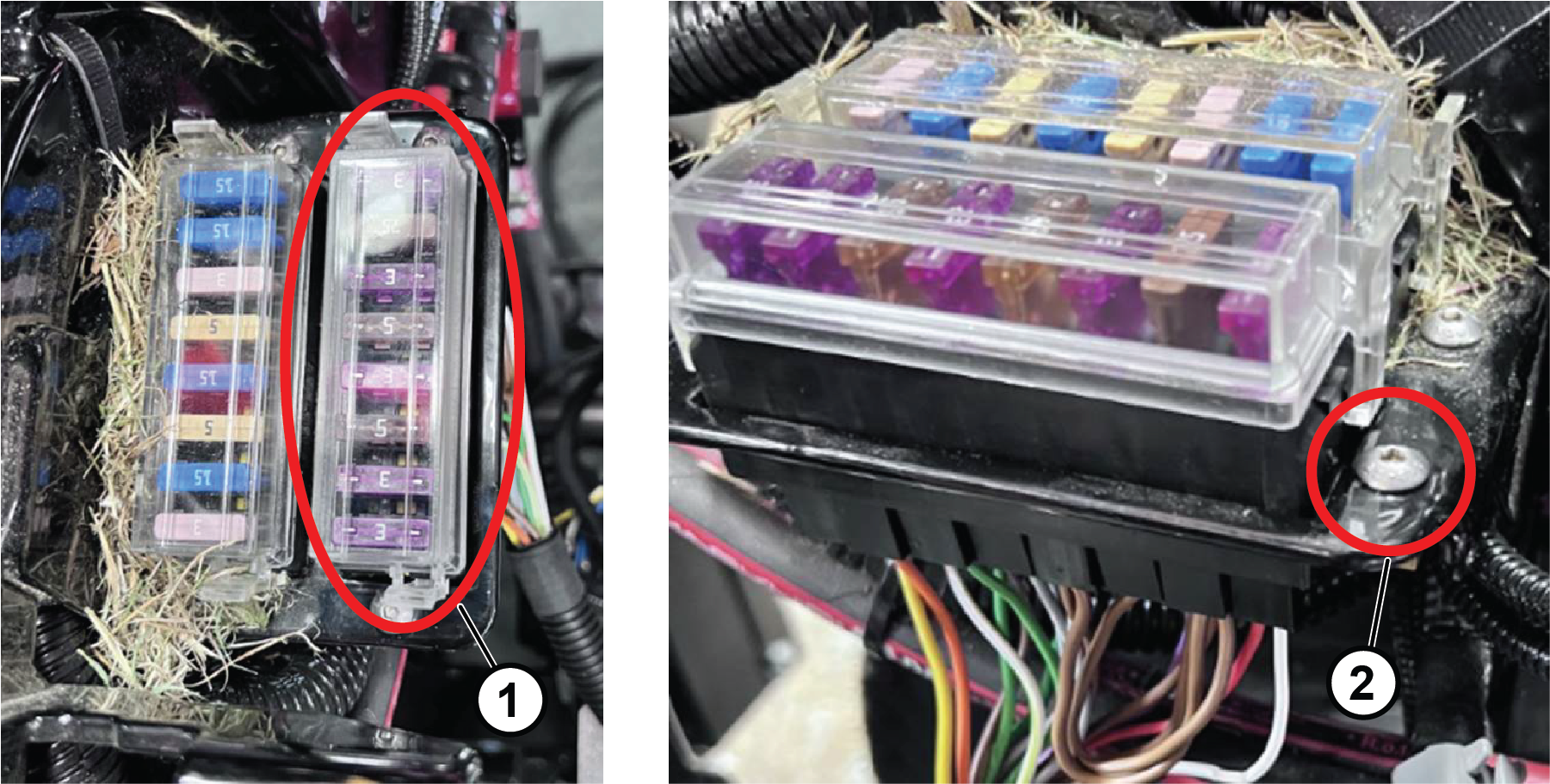
Connect the fuse box by removing plastic cover and feed the fuse box from the bottom of the bracket. Secure the plastic cover on the fuse box and fasten it to the bracket with the 2 existing screws (Figure 17).
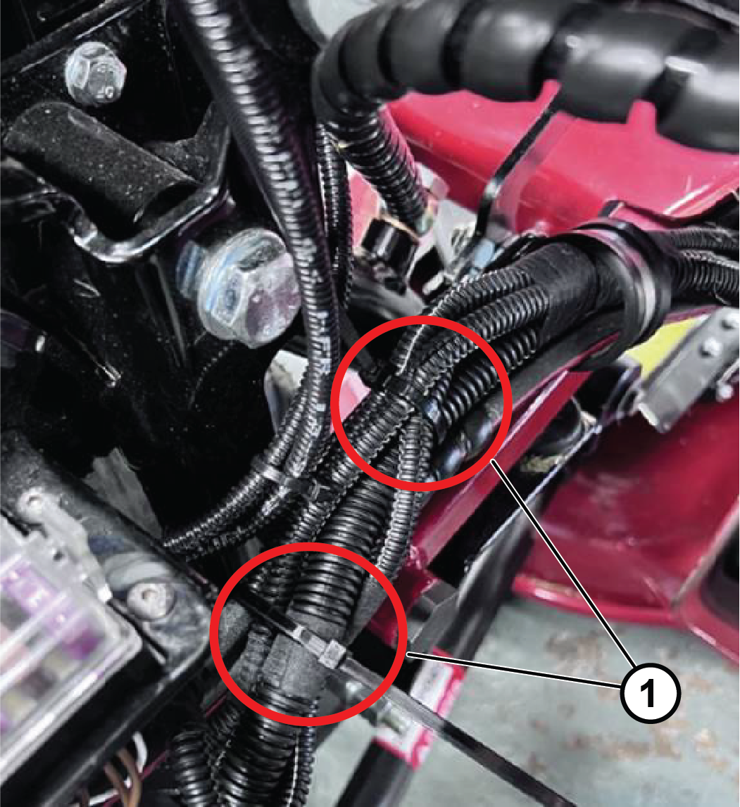
Use 2 cable ties to secure the front section of the wire harness (Figure 18).
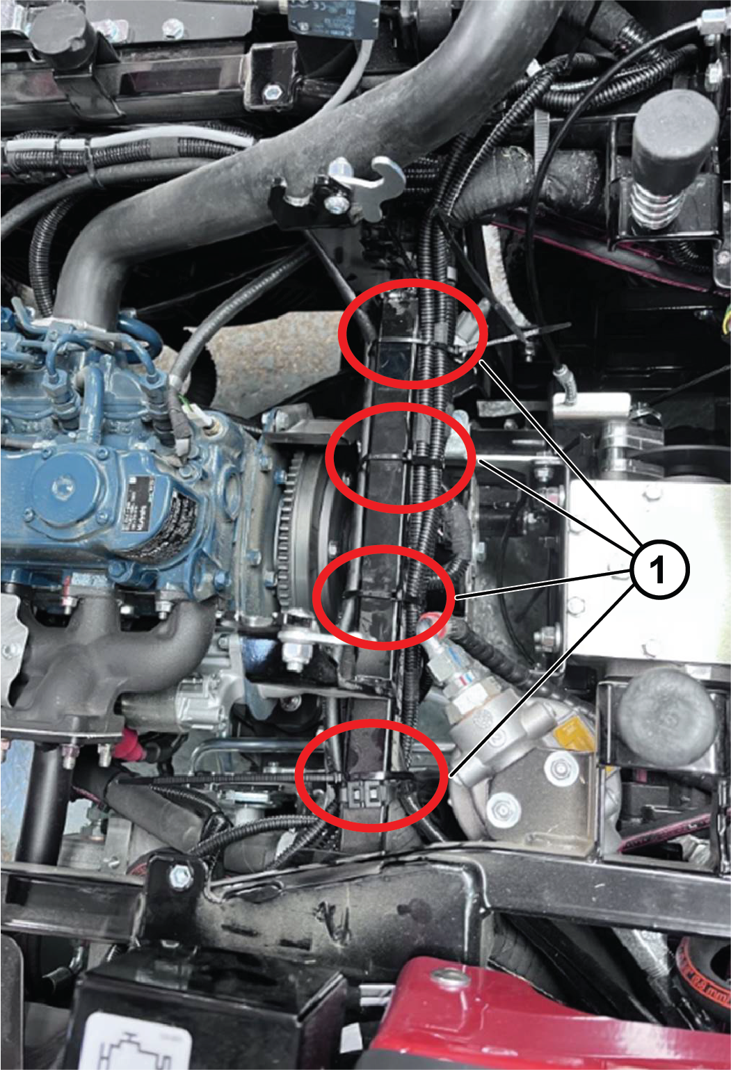
Remove the engine cover plate and route harness for the rear lights below the seat. Secure the harness to the chassis membrane using 4 cable ties as shown in Figure 19.
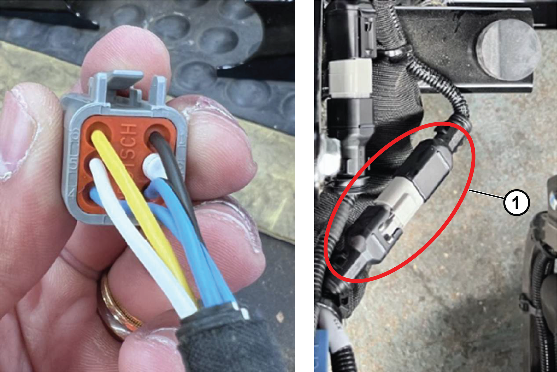
Connect the 5-way connector (per the schematic) to rear light wiring harness assembly (Figure 20).
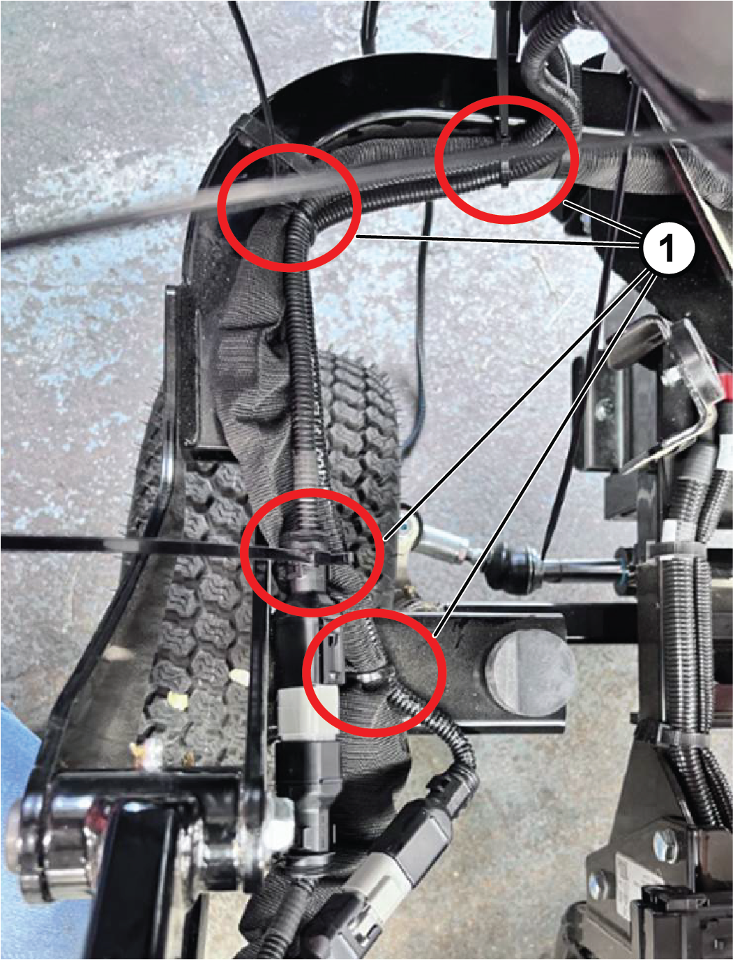
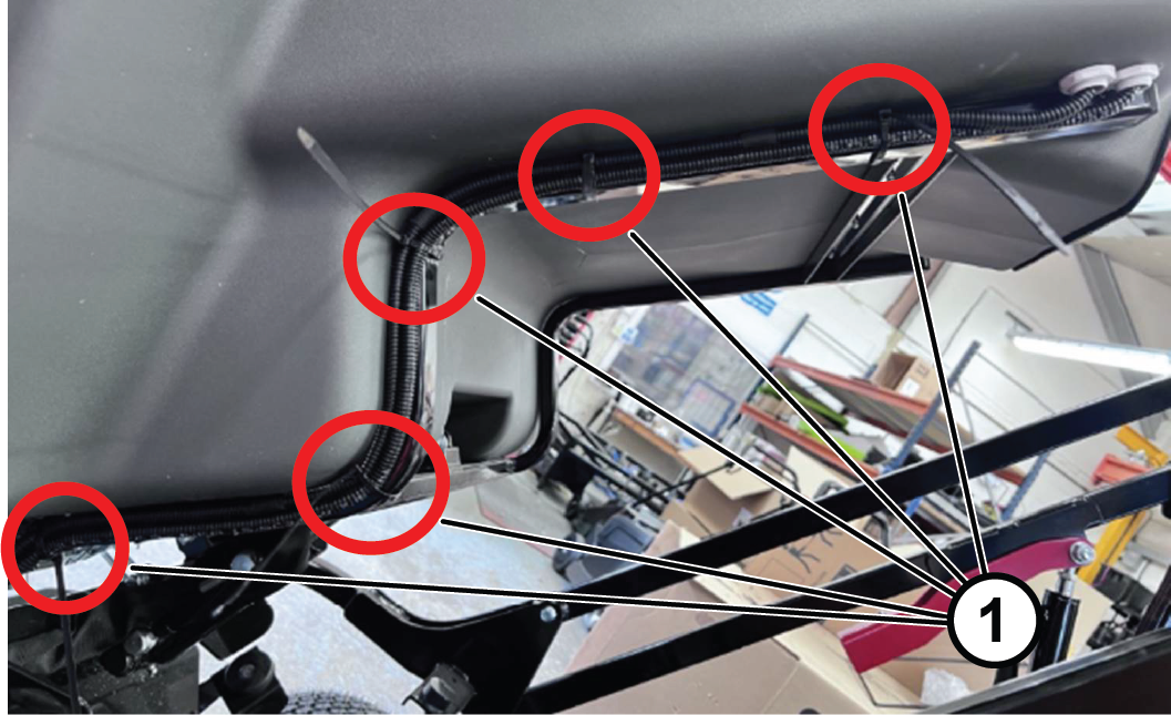
Route the rear-light harness through the rear frame and the hopper frame. Use 9 cable ties to secure the harness as shown in Figure 21 and Figure 22.
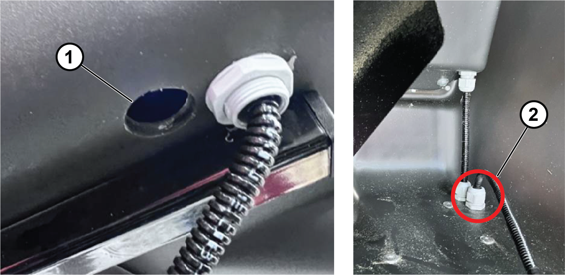
Drill a 21 mm hole from the bottom of the hopper and feed the wire harness through the cable-fitting nut. Secure the cable fitting with the cable fitting nut (Figure 23).
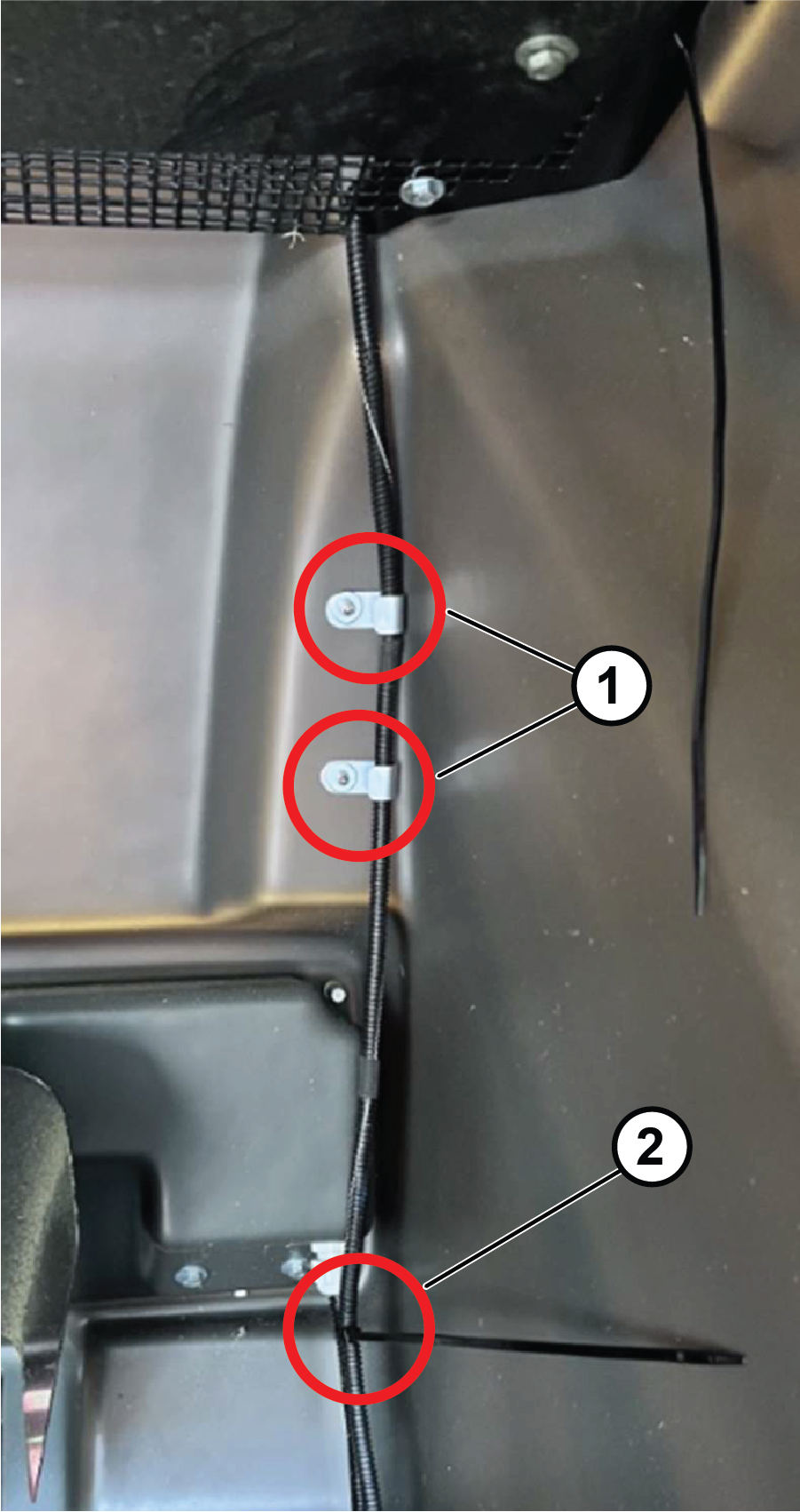
Secure the rear-light wire harness to PLH600 machine wire harness with a cable tie and route the harness through 2 clamps on the front of the hopper.
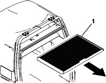
Remove the hopper screen from the machine (Figure 25).
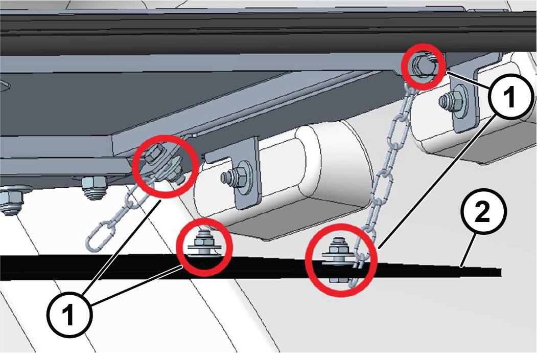
Remove the 4 nuts, 8 washers and 4 screws holding the chain to the plastic grass-catcher panel (Figure 26).
Loosen the 3 screws, 3 washers, and 3 nuts to remove the support grid (Figure 27).
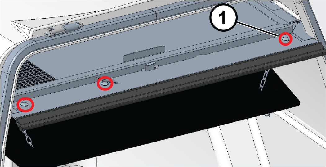
Remove the 2 nuts, 4 washers, and 2 screws from the right removable-grid slide (Figure 28).
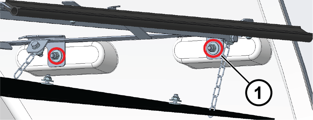
Remove the 2 nuts, 3 washers, 1 washer (M8) and 2 screws from the right removable-grid slide (Figure 29).
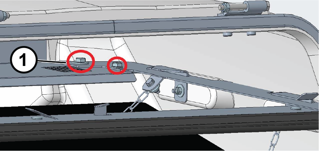
Route the harness through and run the harness alongside the right removable-grid slide, and secure it using 2 cable ties in the locations shown below:
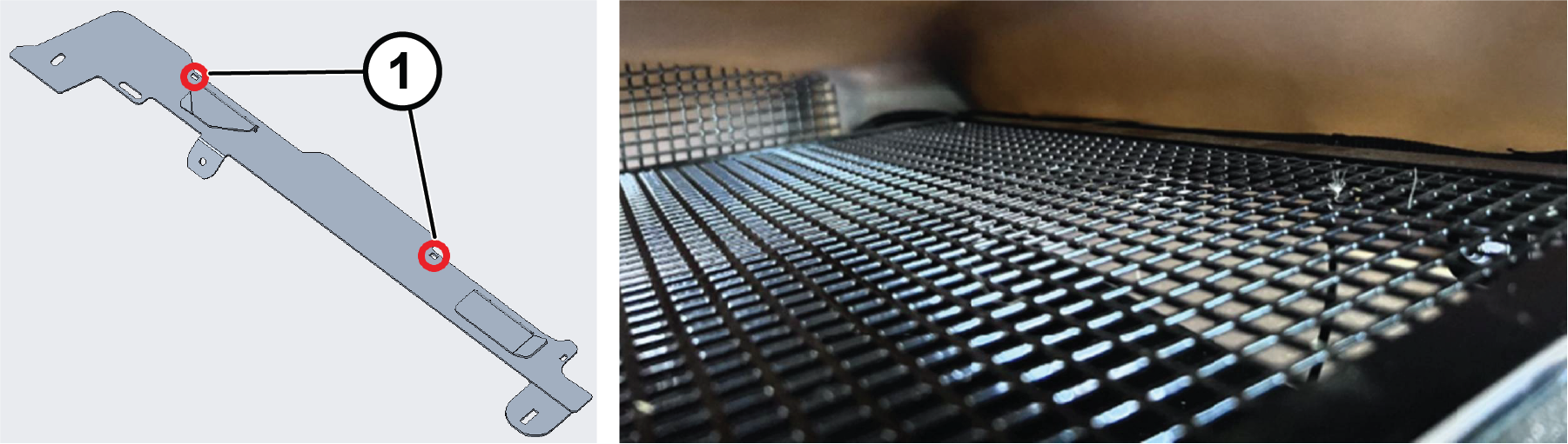
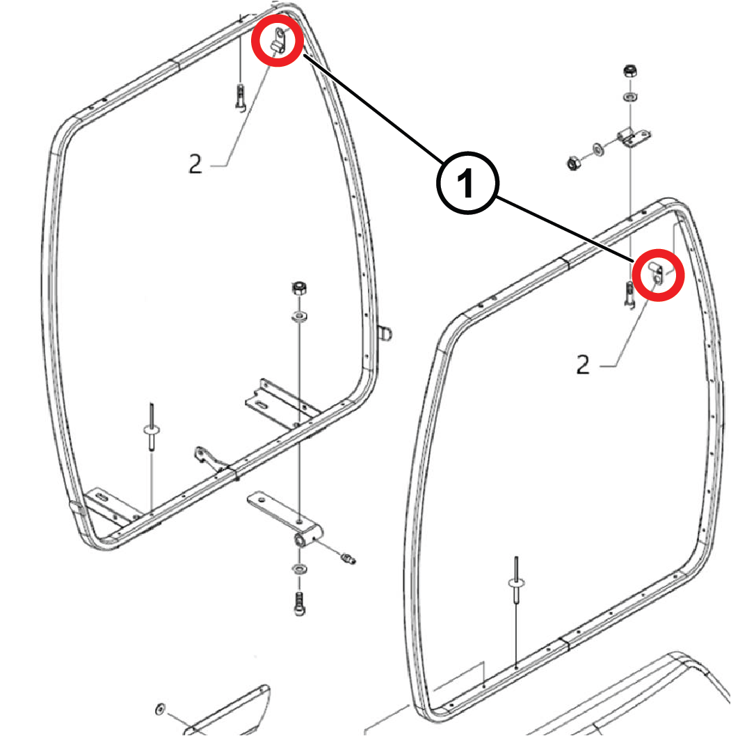
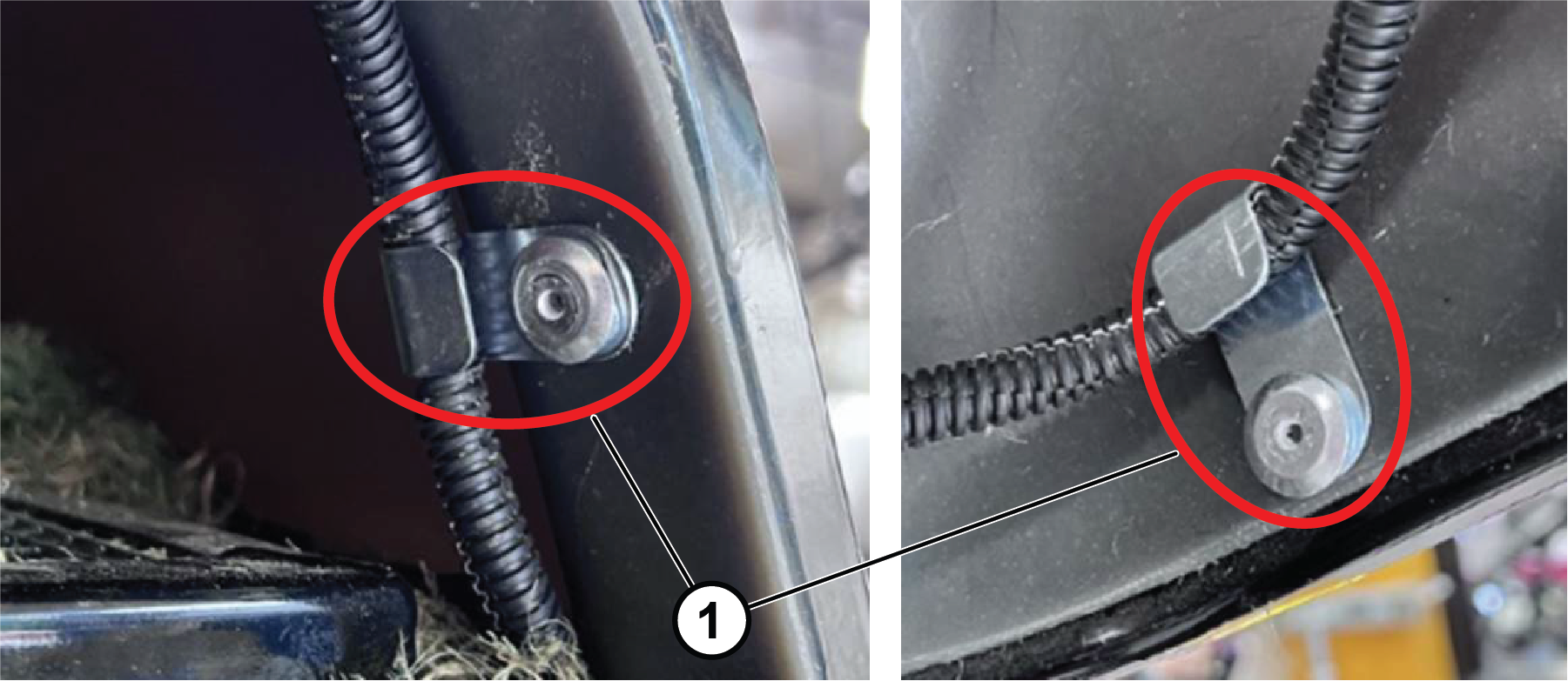
Install the hopper grid assembly and route the harness through the two clamps on the hopper frame and the hopper door frame (Figure 31 and Figure 32).
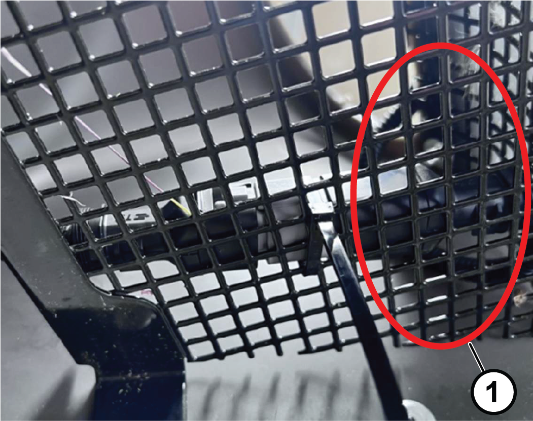
Connect the rear-lights wire assembly to the harness and secure it using a cable tie to hopper door grid.
Refer to the following figures and instructions for routing the control wire harness.
Switch on the hazard warning lights on the control panel and check that all 4 lights flash.
Switch on the light switch on the light control lever by turning the toggle forward to activate the road lights. Rotate the toggle forward once more to activate the low beam front lights. Ensure both have lit.
Check that each direction indicator light works. Ensure the correct lamp flashes when selected at the control arm switch.
Check the horn by pressing the outside face of the lever inwards.
Switch off the ignition switch. If anything is not working, check the connections to the element that is failing and its relevant switch. Ensure all ground and battery connections are good.
Connect the battery; refer to the electrical system maintenance section of your Operator’s Manual.
The light controls on the control panel are marked with the symbols shown below:
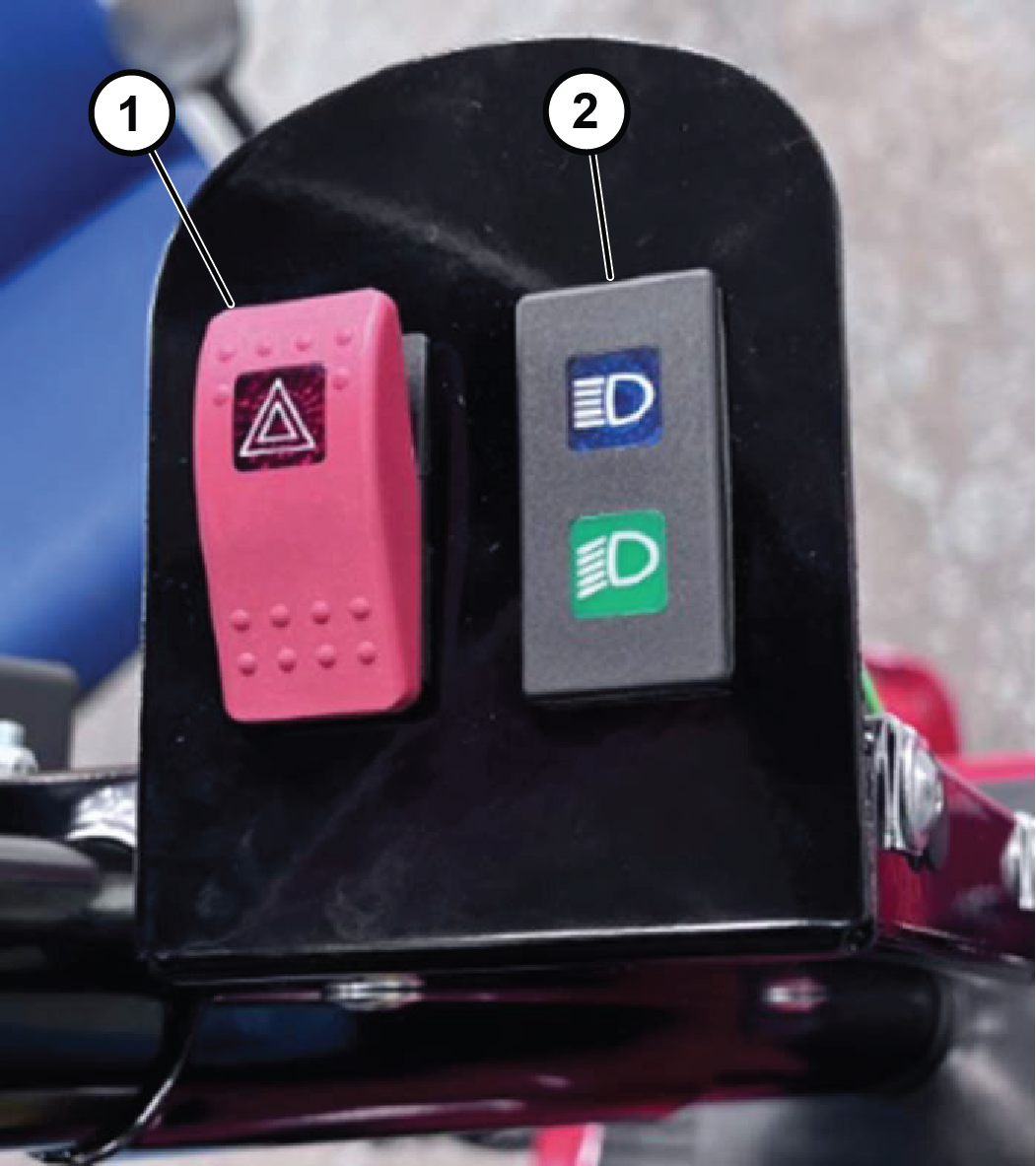
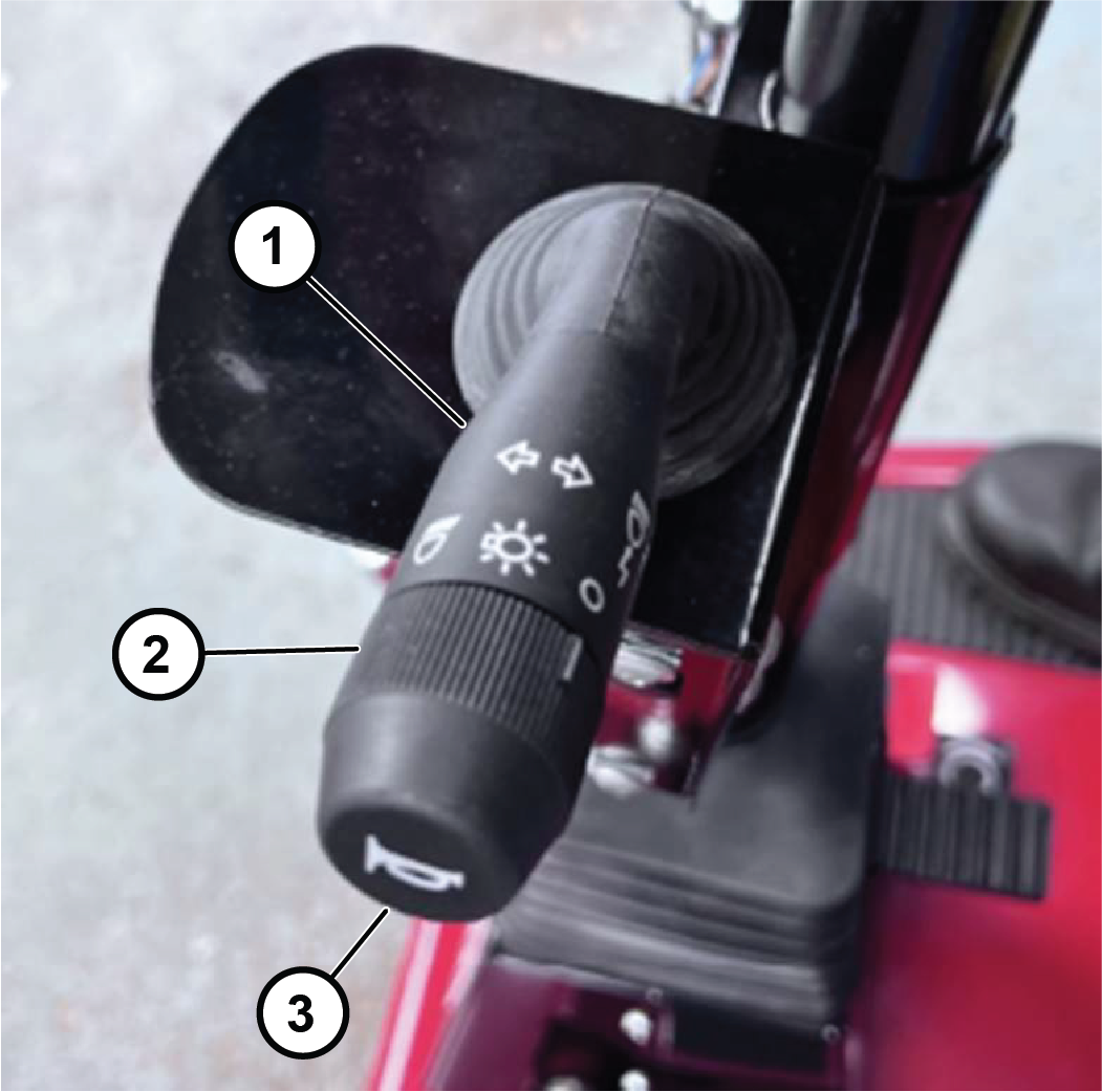
To Illuminate the low beam lights, run the engine and turn the light switch counterclockwise on the control panel.
To Illuminate the high beam lights, run the engine an turn the light switch twice counter clockwise on the control canel.
To switch off the lights, turn the light switch once or twice clockwise on the control panel.
Press the top of the hazard light switch to flash all indicator lights simultaneously.
Note: You do not need to have the ignition switch in the RUN position.
To switch the beacon on, push the top of the beacon switch
Replace all worn or damaged parts with genuine Toro parts.
Periodically check that all lights are working.
Ensure that the headlights are adjusted correctly.
Clean the lights daily.
Schematic