This kit contains parts to install new HyperCell® batteries (which replace the existing Samsung batteries and associated parts) to the Greensmaster eTriFlex 3370 traction unit.
Installation
Caution
Removing or installing the batteries may result in personal injury and property damage.
When removing or installing the batteries, follow these recommendations:
-
Always disconnect the main-power connectors when servicing products with lithium-ion batteries.
-
Always service lithium-ion batteries with the machine parked near a service door large enough to move the product or battery outside in case of an emergency, and keep a fire blanket nearby. Do not use a fire extinguisher on lithium-ion batteries.
-
Do not allow the battery terminals or battery cables to touch any metal parts of the machine.
-
Do not allow metal tools to short between the battery terminals or battery cables and metal parts of the machine.
-
Do not attach anything to the battery terminal other than the battery cable or wire harness connector that came with the product.
-
Always keep the battery retainers and covers in place to protect and secure the batteries.
Preparing the Machine
-
Park the machine on a level surface.
-
Engage the parking brake.
-
Lower the cutting units.
-
Shut off the machine and remove the key.
-
Disconnect the main-power connectors; refer to your machine Operator’s Manual.
-
Raise the machine; refer to the pre-maintenance section of your machine Operator’s Manual.
-
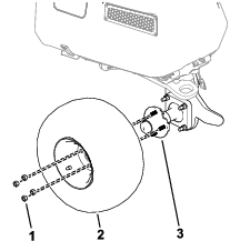
Remove the 4 lugnuts that secure the wheel to the wheel-hub assembly and remove the wheel from the machine (Figure 1).
Removing the Samsung Batteries, Battery Trays, and Associated Parts
Removing the Samsung Batteries, Cables, and Wire Harness
For instructions to remove the Samsung batteries, center battery cover, battery cables, and battery-interface wire harness, refer to the Servicing the Lithium-Ion Batteries (Model 04590) section in the machine Service Manual.
Retain the center battery cover for later installation.
Note: Labels for wire harness and cable connections are not necessary.
Removing the Battery Trays
-
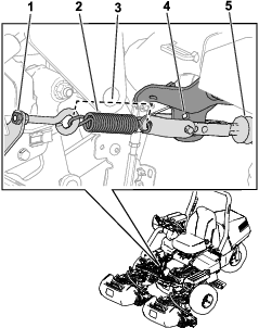
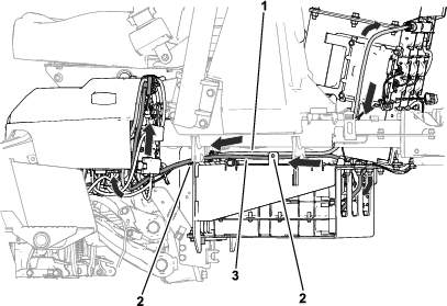
Release tension on the brake-actuator spring by loosening the nut (Figure 2) that secures the eyebolt to the spring bracket.
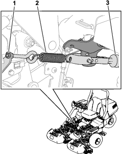
-
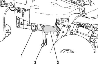
Remove the pins that secure the brake actuator to the side battery tray on the right side of the machine (Figure 3).
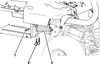
-
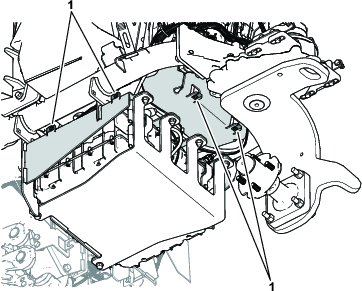
Remove the hardware (Figure 4) that secures the side battery trays to the machine frame.
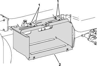
-
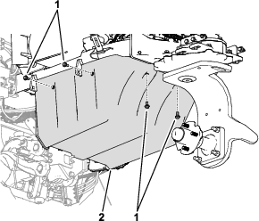
Remove the hardware that secures the top battery tray to the machine frame (Figure 5).
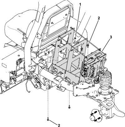
-
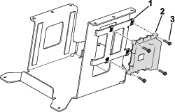
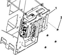
Remove the nuts that secure the TEC controller to the battery tray (Figure 6). Retain the controller for later installation.
Installing the Upper Mount Plate
Parts needed for this procedure:
| Upper mount plate | 1 |
| Flange bolt (5/16 x 1 inch) | 2 |
| Flange nut (5/16 inch) | 2 |
| Flange bolt (3/8 x 1 inch) | 2 |
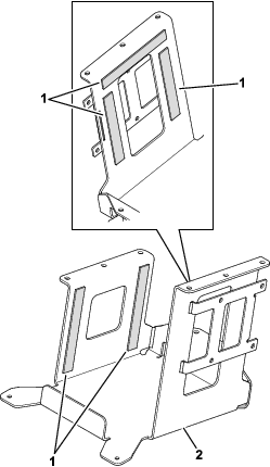
| Foam strip—19 cm (7.5 inches) | 5 |
| Flange bolt (1/4 x 1-1/4 inches) | 4 |
| Speed nut (1/4 inch) | 4 |
Installing Foam Strips and the TEC Controller to the Upper Mount Plate
Installing the Upper Mount Plate to the Machine
-
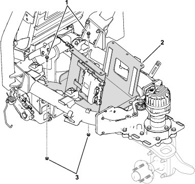
Use 2 flange bolts (5/16 x 1 inch) and 2 flange nuts (5/16 inch) to secure the upper mount plate to the machine frame (Figure 9).
Torque the hardware to 19 to 24 N∙m (14 to 18 ft-lb).
-
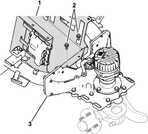
Use 2 flange bolts (3/8 x 1 inch) to secure the upper mount plate to the steering housing (Figure 10).
Torque the bolts to 32.5 to 40.5 N∙m (24 to 30 ft-lb).
Installing the HyperCell Batteries
Parts needed for this procedure:
| HyperCell battery | 5 |
| Top strap | 1 |
| Bottom base plate | 1 |
| Foam strip—19 cm (7.5 inches) | 4 |
| Flange bolt (3/8 x 1 inch) | 12 |
| Flange nut (3/8 inch) | 12 |
| Bus bar | 6 |
| Bolt (1/4 x 3/4 inch) | 10 |
| Data-interface wire harness (63.5 cm or 25 inches) | 1 |
| Data-interface wire harness (19 cm or 7-1/2 inches) | 3 |
| Black battery cable | 1 |
| Red battery cable | 1 |
| Red/black battery-cable assembly | 1 |
| Lower mount plate | 1 |
| Model 04593 decal | 1 |
| Carriage bolt (3/8 x 1 inch) | 4 |
| Flange nut (3/8 inch) | 4 |
| Foam strip—37 cm (14.5 inches) | 2 |
Installing the Batteries to the Upper Mount Plate
-
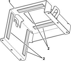
Install 5 foam strips (19 cm or 7.5 inches) to the top strap bracket (Figure 11).
-
Perform the following steps to install 3 batteries to the upper mount plate:
-
Remove the cap (Figure 12) from the positive terminals.
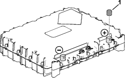
-
Align the outer batteries so that they are positioned against the left and right sides of the upper mount plate (Figure 13).
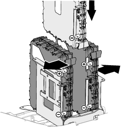
-
Align the center battery so that the battery terminals face rearward, and lower the center battery into the upper mount plate, between the outer batteries (Figure 13).
-
-
Use 6 flange bolts (3/8 x 1 inch) and 6 flange nuts (3/8 inch) to secure the top strap to the upper mount plate (Figure 14).
Torque the hardware to 32.5 40.5 N∙m (24 to 30 ft-lb).
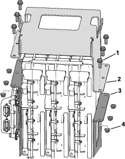
Installing the Bus Bars, Battery Cables, and Data-Interface Wire Harnesses to the Upper Batteries
-
Install 2 data-interface wire harnesses (19 cm or 7-1/2 inches) into the battery ports shown in Figure 15.
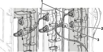
-
Install an end of the data-interface wire harness (63.5 cm or 25 inches) into the battery port labeled D2 as shown in Figure 15.
-
Use 6 bolts (1/4 x 3/4 inch) to secure the following items to the battery terminals (Figure 16).
-
4 bus bars
-
Red (+) battery cable
-
Black (-) battery cable
-
Red (+) battery cable on the red/black battery-cable assembly
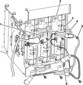
-
-
Torque the bolts (1/4 x 3/4 inch) to 10.7 to 11.8 N∙m (95 to 105 in-lb).
Installing the Lower Batteries
-
Remove the cap (Figure 17) from the positive terminals of the remaining 2 batteries.

-
Assemble the 2 batteries on the bottom base plate as shown in Figure 18.
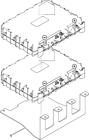
-
Install 2 foam strips (37 cm or 14.5 inches) to the lower mount plate (Figure 19).
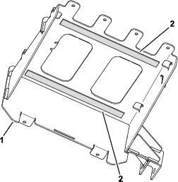
-
Install the Model 04593 decal to the lower mount plate as shown in Figure 20.
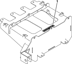
-
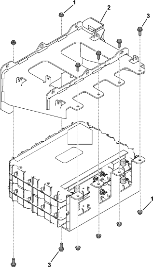
Use 6 flange bolts (3/8 x 1 inch) and 6 flange nuts (3/8 inch) to loosely secure the lower mount plate to the bottom base plate (Figure 21)
-
Ensure that the batteries are centered in the base plate and torque the hardware to 32.5 to 40.5 N∙m (24 to 30 ft-lb).
-
Use a floor jack to install the assembly that contains the bottom base plate, batteries, and lower mount plate as follows:
-
Place the assembly on a floor jack.
Important: The batteries and base plate weigh approximately 34 kg (75 lb). Have an assistant help you to ensure that the batteries and base plate are centered on the floor jack. Keep the center of the batteries and base plate aligned to the jack to prevent the batteries from falling.
-
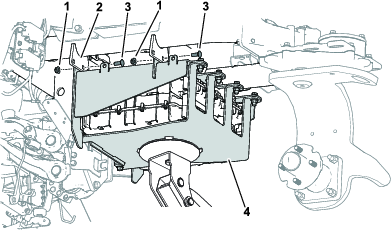
Use 4 carriage bolts (3/8 x 1 inch) and 4 flange nuts (3/8 inch) to secure the battery assembly to the machine frame (Figure 22).
Torque the hardware to 32.5 to 40.5 N∙m (24 to 30 ft-lb).
-
Installing the Brake Actuator to the Lower Mount Plate
Installing the Bus Bars, Battery Cables, and Data-Interface Wire Harnesses to the Lower Batteries
-
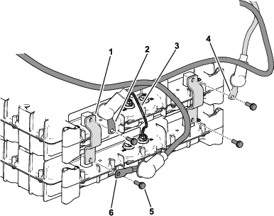
Use 4 bolts (1/4 x 3/4 inch) to secure the following items to the battery terminals (Figure 25):
-
2 bus bars
-
Red (+) battery cable
-
Black (-) battery cable
-
Black (-) battery cable on the red/black battery-cable assembly
-
-
Install a data-interface wire harness (19 cm or 7-1/2 inches) to the battery ports shown in Figure 25.
-
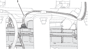
Install the remaining end of the data-interface wire harness (63.5 cm or 25 inches) to the upper-battery port shown in Figure 26.
-
Torque the bolts (1/4 x 3/4 inch) to 10.7 to 11.8 N∙m (95 to 105 in-lb).
Routing the Red/Black Battery-Cable Assembly
Installing the BMS Wire Harness and Other Wire-Harness Connections
Parts needed for this procedure:
| BMS wire harness | 1 |
| Cable tie | 6 |
-
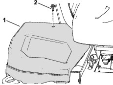
Remove the cover from the right side of the machine (Figure 28).
-
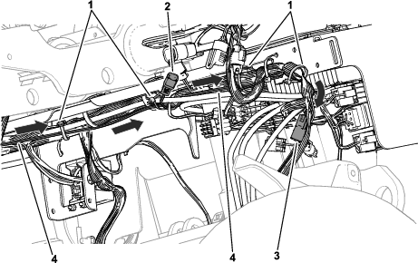
Route the BMS wire harness to the battery packs (Figure 29) and along the machine wire harness under the right side of the machine (Figure 30).
Connect the wire-harness connectors to the following ports:
Wire-harness connector label Connection P02 P12 connector (machine wire harness) P03 Battery port D1 (left outer battery in top battery stack) P06 Battery port D2 (bottom battery in bottom battery stack) P04 P65 connector (machine wire harness)Remove the resistor from the P65 connector before installing the BMS P04 connector. P01 P58 connector (machine wire harness)Remove the resistor from the P58 connector before installing the BMS P01 connector. 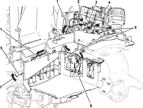
-
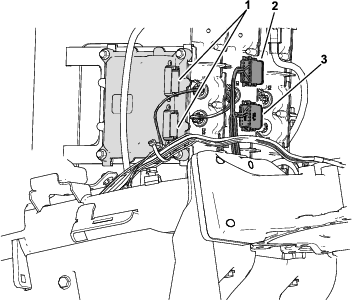
Secure the existing machine wire-harness connectors labeled P02 and P03 to the TEC controller (Figure 31).
Installing the Lower Battery Cover
Installing the Charging Connectors
Parts needed for this procedure:
| Charging connectors | 1 |
| Connector bracket | 1 |
| Bolt (#6) | 2 |
| Locknut (#6) | 2 |
| Fuse bracket | 1 |
Removing the Existing Parts from the Machine Frame
-
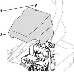
Remove the left side cover from the machine (Figure 34).
-
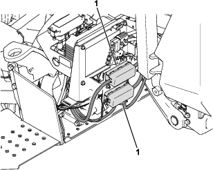
Remove and retain the fuse assemblies (fuses and cables) from the fuse bracket (Figure 35).
-
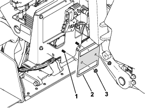
Remove the existing fuse bracket from the frame (Figure 36). Retain the hardware.
-
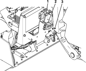
Remove the existing charging connector from the frame (Figure 37). Retain the connector and hardware.
Installing the Charging Connectors
-
Use the previously removed flange bolt (1/4 inch) and flange nut (1/4 inch) to secure the connector bracket and fuse bracket to the frame (Figure 38).
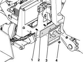
-
Secure the new charging connectors to the existing charging connectors (Figure 39).
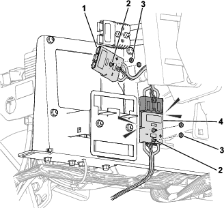
-
Use the new bolts (#6) and locknuts (#6) and previously removed bolts (#6) and locknuts (#6) to secure the charging connectors to the frame and the connector bracket (Figure 39).
-
Install the fuse assemblies to the new fuse bracket (Figure 35).
-
Install the left side cover (Figure 34).
Installing the CAN Wire Harness, DC-DC Converter, and Connector Caps
Parts needed for this procedure:
| CAN wire harness | 1 |
| DC-DC converter | 1 |
| Tethered cap | 1 |
| 6-socket cap | 1 |
Installing the CAN Wire Harness and DC-DC Converter
-
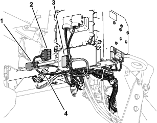
Unplug the wire-harness connector from the existing DC-DC converter (Figure 40) and remove the converter from the machine frame.
Retain the hardware (i.e., the 2 bolts and 2 nuts) that secured the converter to the frame.
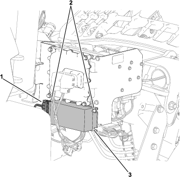
-
Use the existing hardware to secure the new DC-DC converter to the machine frame (Figure 41).
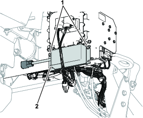
-
Install the CAN-wire-harness connectors as follows (Figure 42):
-
Connector for the CAN wire harness labeled P04: Connect to the DC-DC converter connector.
-
Connector for the CAN wire harness labeled P03: Connect to the machine-wire-harness connector labeled P07 (the connector that you disconnected from the existing DC-DC converter).
-
Installing the Connector Caps
-
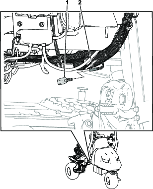
Locate the wire-harness connector labeled P09 near the center cutting unit, charging connectors, and fuse holders (Figure 43).
-
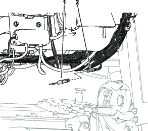
Remove the diode from the wire-harness connector labeled P09 (Figure 43) and install the tethered cap to the connector (Figure 44).
-
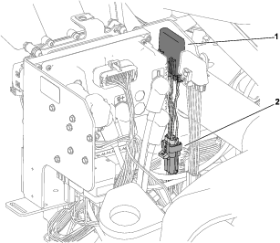
Remove the CAN bus isolation module from the wire-harness connector labeled P50 (Figure 45) and remove the isolation module from the machine.
-
Install the 6-socket cap to the wire-harness connector labeled P50 (Figure 46).
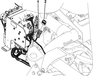
-
Install the cover to the right side of the machine (Figure 47).

Installing the Center Battery Cover
Use the previously removed hardware and clamps to secure the center battery cover to its previous position on the machine (Figure 48).
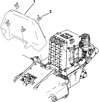
Installing the Jack Bracket
Parts needed for this procedure:
| Jack bracket | 1 |
-
Use the existing bolts (7/16 inch) from the steering housing (near the steering unit) to secure the jack bracket to the steering housing (Figure 49).
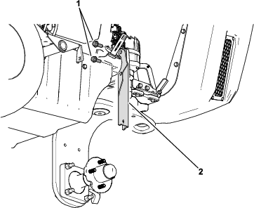
-
Torque the bolts to 75 to 81 N∙m (55 to 60 ft-lb).
Installing the Hood Latch
Parts needed for this procedure:
| Latch | 1 |
| Spacer | 1 |
| Latch plate | 1 |
| Latch bracket | 1 |
| Rivet | 2 |
Caution
Using a drill without proper eye protection may allow debris to enter the eyes, causing injury.
When drilling, always wear eye protection.
-
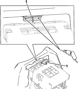
Use a drill bit (7/8 inch) to drill a hole into a centered area of the hood as shown in Figure 50.
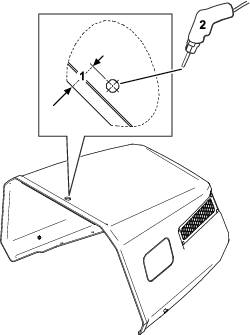
-
Using the latch bracket as a template, mark and drill 2 holes (3/16-inch drill bit) into a centered area of the battery cover (Figure 51).
-
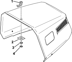
Use the latch jam nut, spacer, and latch plate to secure the latch to the hood (Figure 52).
-
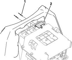
Use 2 rivets to secure the latch bracket to the battery cover (Figure 53).
Using Toro DIAG to Update the Software
-
Connect Toro DIAG to the machine; refer to the Toro DIAG Software User’s Guide and the Toro DIAG Commercial Product User’s Guide.
-
Update the model number to 04593 and the serial number to the appropriate serial number for your Battery Conversion Kit.
Note: This step is completed while Toro DIAG is attempting to retrieve the machine model number and serial number; refer to the Establish Communication with the Machine section in the Toro DIAG Software User’s Guide.
-
Ensure that the software revision level for the batteries is updated by selecting the REPROGRAM button in Toro DIAG; refer to the Toro DIAG Software User’s Guide.
Charging the Batteries
Parts needed for this procedure:
| Battery charger | 1 |
Use the battery charger to charge the batteries; refer to the battery charging instructions in the Greensmaster eTriFlex 3370 (Model 04591) Operator’s Manual.
Installing the Rear Wheel
Use the previously removed 4 lugnuts to secure the rear wheel to the wheel-hub assembly (Figure 54).

