| Maintenance Service Interval | Maintenance Procedure |
|---|---|
| Before each use or daily |
|
Introduction
This machine is a ride-on, rotary-blade lawn mower intended to be used by professional, hired operators in commercial applications. It is primarily designed for cutting grass on well-maintained lawns in parks, sports fields, and on commercial grounds. Using this product for purposes other than its intended use could prove dangerous to you and bystanders.
Read this information carefully to learn how to operate and maintain your product properly and to avoid injury and product damage. You are responsible for operating the product properly and safely.
Visit www.Toro.com for product safety and operation training materials, accessory information, help finding a dealer, or to register your product.
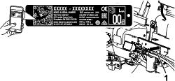
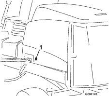
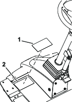
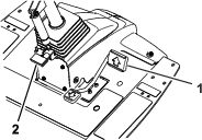
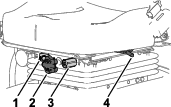
Whenever you need service, genuine Toro parts, or additional information, contact an Authorized Service Dealer or Toro Customer Service and have the model and serial numbers of your product ready. Figure 1 identifies the location of the model and serial numbers on the product. Write the numbers in the space provided.
Important: With your mobile device, you can scan the QR code on the serial number decal (if equipped) to access warranty, parts, and other product information.
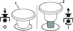
This manual identifies potential hazards and has safety messages identified by the safety-alert symbol (Figure 2), which signals a hazard that may cause serious injury or death if you do not follow the recommended precautions.

This manual uses 2 words to highlight information. Important calls attention to special mechanical information and Note emphasizes general information worthy of special attention.
This product complies with all relevant European directives; for details, please see the separate product specific Declaration of Conformity (DOC) sheet.
It is a violation of California Public Resource Code Section 4442 or 4443 to use or operate the engine on any forest-covered, brush-covered, or grass-covered land unless the engine is equipped with a spark arrester, as defined in Section 4442, maintained in effective working order or the engine is constructed, equipped, and maintained for the prevention of fire.
The enclosed engine owner's manual is supplied for information regarding the US Environmental Protection Agency (EPA) and the California Emission Control Regulation of emission systems, maintenance, and warranty. Replacements may be ordered through the engine manufacturer.
Warning
CALIFORNIA
Proposition 65 Warning
Diesel engine exhaust and some of its constituents are known to the State of California to cause cancer, birth defects, and other reproductive harm.
Battery posts, terminals, and related accessories contain lead and lead compounds, chemicals known to the State of California to cause cancer and reproductive harm. Wash hands after handling.
Use of this product may cause exposure to chemicals known to the State of California to cause cancer, birth defects, or other reproductive harm.
Safety
General Safety
This product is capable of amputating hands and feet and of throwing objects. Always follow all safety instructions to avoid serious personal injury.
-
Read and understand the contents of this Operator’s Manual before starting the engine.
-
Use your full attention while operating the machine. Do not engage in any activity that causes distractions; otherwise, injury or property damage may occur.
-
Do not operate the machine without all guards and other safety protective devices in place and functioning properly on the machine.
-
Keep your hands and feet away from rotating parts. Keep clear of the discharge opening.
-
Keep bystanders and children out of the operating area. Never allow children to operate the machine.
-
Shut off the engine, remove the key, and wait for all movement to stop before you leave the operator’s position. Allow the machine to cool before adjusting, servicing, cleaning, or storing it.
Improperly using or maintaining this machine can result in injury.
To reduce the potential for injury, comply with these safety instructions
and always pay attention to the safety-alert symbol  , which means Caution, Warning,
or Danger—personal safety instruction. Failure to comply with
these instructions may result in personal injury or death.
, which means Caution, Warning,
or Danger—personal safety instruction. Failure to comply with
these instructions may result in personal injury or death.
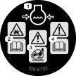
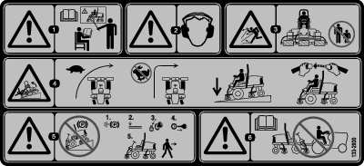
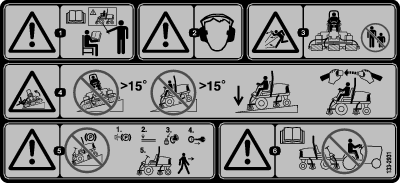
Safety and Instructional Decals
|
Safety decals and instructions are easily visible to the operator and are located near any area of potential danger. Replace any decal that is damaged or missing. |


CE Machines
Setup
Note: Determine the left and right sides of the machine from the normal operating position.
Preparing the Machine
Checking the Tire Pressure
Check the tire pressure before use; refer to Checking the Tire Pressure.
Important: Maintain pressure in all tires to ensure a good quality-of-cut and proper machine performance. Do not underinflate the tires.
Checking the Fluid Levels
-
Check the engine-oil level before starting the engine; refer to Checking the Engine-Oil Level.
-
Check the hydraulic-fluid level before starting the engine; refer to Checking the Hydraulic-Fluid Level.
-
Check the cooling system before starting the engine; refer to Checking the Cooling System.
Greasing the Machine
Grease the machine before use; refer to Greasing the Bearings and Bushings. Failure to properly grease the machine results in premature failure of critical parts.
Removing the Shipping Blocks and Pins
-
Remove and discard the shipping blocks from the cutting units.
-
Remove and discard the shipping pins from the cutting-unit suspension arms.
Note: The shipping pins stabilize the cutting units during shipping; remove them before operating the machine.
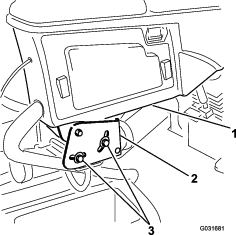
Adjusting the Control Arm Position
You can adjust the control arm position for your comfort.
-
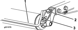
Loosen the 2 bolts securing the control arm to the retaining bracket (Figure 3).
-
Rotate the control arm to the desired position and tighten the 2 bolts.
Adjusting the Machine Software (CE Machines Only)
Contact your authorized Toro distributor to set the machine software to the CE mode.
Installing the Hood Latch
For CE Compliance
Parts needed for this procedure:
| Hood-latch assembly | 1 |
| Washer | 1 |
-
Unlatch and raise the hood.
-
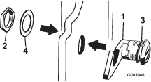
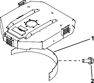
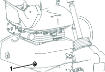
Remove the rubber grommet from the hole in the left side of the hood (Figure 4).
-
Remove the nut from the hood-latch assembly (Figure 5).
-
On the outside of the hood, insert the hook end of the latch through the hole in the hood and ensure that the rubber-sealing washer remains to the outer side of the hood (Figure 5).
-
On the inside of the hood, insert the metal washer onto the latch, secure the latch with the nut, and ensure that the latch engages the frame catch when it is locked.
Note: Use the enclosed hood-latch key to operate the hood latch.
Applying the CE Decals
Parts needed for this procedure:
| CE decal | 1 |
| Production year decal | 1 |
| Warning decal | 1 |
Applying the CE Decal
-
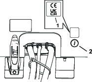
Use rubbing alcohol and a clean rag to clean the area of the hood next to the hood lock, and allow the hood to dry. (Figure 6).
-
Remove the backing from the CE decal.
-
Apply the decal to the hood.
Applying the Year of Production Decal
-
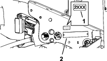
Use rubbing alcohol and a clean rag to clean the floor bracket area next to the serial plate, and allow the bracket to dry (Figure 7).
-
Remove the backing from the year of production decal.
-
Apply the decal to the floor bracket.
Applying the CE Warning Decal
-
Use rubbing alcohol and a clean rag to clean the surface of warning decal, and allow the decal to dry (Figure 8).
-
Remove the backing from the CE warning decal.
-
Apply the CE warning decal over the existing decal.
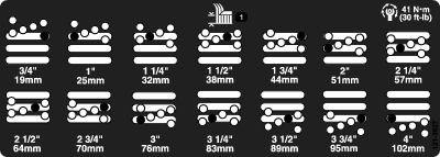
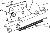
Adjusting the Roller Scraper
Optional
The optional rear roller scraper functions best when there is an even gap of 0.5 to 1 mm (0.02 to 0.04 inch) between the scraper and the roller.
-
Loosen the grease fitting and the mounting screw (Figure 9).
-
Slide the scraper up or down until you obtain a gap of 0.5 to 1 mm (0.02 to 0.04 inch) between the rod and the roller.
-
Tighten the grease fitting and screw to 41 N∙m (30 ft-lb) in an alternating sequence.
Installing the Mulching Baffle
Optional
Contact your authorized Toro distributor for the correct mulching baffle.
-
Thoroughly clean debris from the mounting holes on the rear wall and left wall of the chamber.
-
Install the mulching baffle in the rear opening and secure it with 5 flange-head bolts (Figure 10).
-
Verify that the mulching baffle does not interfere with the tip of the blade and does not protrude inside the surface of the rear chamber wall.
Danger
Using the high-lift blade with the mulching baffle could cause the blade to break, resulting in personal injury or death.
Do not use the high-lift blade with the baffle.
Product Overview
Automotive-Style Throttle
Note: This machine does not have a lever or switch to control the engine speed.
When the PTO is engaged to start spinning the cutting units, the machine automatically changes the engine speed to high idle and stays there until the cutting units are disengaged.
When the PTO is not engaged, the machine’s throttle is dependent on the position of the traction pedal, just like the throttle on a car.
Traction Pedal
Power-takeoff (PTO) Switch
When the PTO switch is engaged, the machine is in MOW mode, which allows you to drive up to 13 km/h (8 mph) when the maximum speed is not limited.
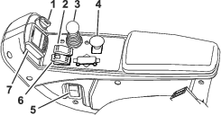
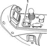
When the PTO switch is not engaged (Figure 11), the machine is in TRANSPORT mode, which allows you to drive up to 16 km/h (10 mph) when the maximum speed is not limited.
Note: Use the protected menus in the InfoCenter to set the maximum speed for each mode.
Parking Brake
To engage the parking brake, (Figure 11) pivot the switch forward on the console. The red light on the switch turns on when it is set. To release the parking brake, pivot the switch backward.
Activating the parking-brake switch causes the traction to automatically decelerate, regardless of traction pedal position, and engage the parking brake as soon as the machine comes to a stop.
Once the engine has been shut off and the machine is not moving, the parking brake engages, regardless of parking-brake switch position.
Tilt-Steering Pedal
To tilt the steering wheel toward you, press the foot pedal down, pull the steering tower toward you to the most comfortable position, and release the pedal (Figure 12). To move the steering wheel away from you, press the foot pedal and release it when the steering wheel reaches the desired operating position.
Lower Mow/Raise Control Lever
This lever (Figure 11) raises and lowers the cutting units.
To lower the cutting units, push the lever forward. When the PTO switch is ENGAGED, the machine is in MOW mode, and the cutting units will start spinning when lowered.
Note: Ensure that you lower the cutting units after the PTO switch has been engaged to start the cutting units. When you lower the cutting units before the PTO switch is engaged, they do not start spinning.
To fully raise the cutting units, pull the lever backward. When the cutting units are raised and the PTO switch is disengaged, the machine is in TRANSPORT mode.
Key Switch
The key switch (Figure 11) has 3 positions: OFF, ON/PREHEAT, and START.
Headlight Switch
Pivot the switch upward to turn on the headlights (Figure 11).
Hydraulic-Filter-Restriction Indicator
The hydraulic-filter-restriction indicator alerts you when the hydraulic filters must be changed; refer to Checking the Hydraulic Lines and Hoses.
Power Point
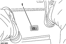
The power point (Figure 15) is a 12 V power supply for electronic devices.
Seat Controls
Seat-Position Lever
Pull the seat-position lever (Figure 16) to move the seat forward and rearward. Release the lever to lock the seat position.
Weight-Adjusting Knob
Rotate the weight-adjusting knob until your weight is displayed in the window of the weight gauge.
Height-Adjusting Knob
Rotate the height-adjusting knob to change the height of the seat.
InfoCenter
The InfoCenter LCD display shows information about your machine, such as the operating status, various diagnostics, and other information about the machine (Figure 11).
The screens that display, depend on which buttons you select. The purpose of each button may change depending on what is required at the time.
Note: Specifications and design are subject to change without notice.
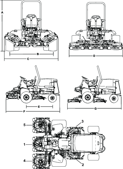
| Description | Figure 17 reference | Dimension or Weight |
| Overall height | A | 217 cm (85.5 inches) |
| Wheel tread (tire center to center) rear | B | 185 cm (72.5 inches) |
| Overall width (transport position) | C | 231 cm (91 inches) |
| Overall width (mowing position) | D | 247 cm (97 inches) |
| Wheel base | E | 152 cm (60 inches) |
| Overall length (transport position) | F | 315 cm (124 inches) |
| Overall length (mowing position) | G | 315 cm (124 inches) |
| Fuel-tank capacity | 53 L (14 US gallons) | |
| Transport speed | 0 to 16 km/h (0 to 10 mph) | |
| Mowing speed | 0 to 13 km/h (0 to 8 mph) | |
| Net weight (with cutting decks and fluids) | 1492 kg (3,289 lb) |
Attachments/Accessories
A selection of Toro approved attachments and accessories is available for use with the machine to enhance and expand its capabilities. Contact your Authorized Service Dealer or authorized Toro distributor or go to www.Toro.com for a list of all approved attachments and accessories.
To ensure optimum performance and continued safety certification of the machine, use only genuine Toro replacement parts and accessories. Replacement parts and accessories made by other manufacturers could be dangerous, and such use could void the product warranty.
Operation
Note: Determine the left and right sides of the machine from the normal operating position.
Before Operation
Before Operation Safety
General Safety
-
Never allow children or untrained people to operate or service the machine. Local regulations may restrict the age of the operator. The owner is responsible for training all operators and mechanics.
-
Become familiar with the safe operation of the equipment, operator controls, and safety signs.
-
Shut off the engine, remove the key, and wait for all movement to stop before you leave the operator’s position. Allow the machine to cool before adjusting, servicing, cleaning, or storing it.
-
Know how to stop the machine and shut off the engine quickly.
-
Check that operator-presence controls, safety switches, and guards are attached and functioning properly. Do not operate the machine unless they are functioning properly.
-
Before mowing, always inspect the machine to ensure that the blades, blade bolts, and cutting assemblies are in good working condition. Replace worn or damaged blades and bolts in sets to preserve balance.
-
Inspect the area where you will use the machine and remove all objects that the machine could throw.
-
This product generates an electromagnetic field. If you wear an implantable electronic medical device, consult your health care professional before using this product.
Fuel Safety
-
Use extreme care in handling fuel. It is flammable and its vapors are explosive.
-
Extinguish all cigarettes, cigars, pipes, and other sources of ignition.
-
Use only an approved fuel container.
-
Do not remove the fuel cap or fill the fuel tank while the engine is running or hot.
-
Do not add or drain fuel in an enclosed space.
-
Do not store the machine or fuel container where there is an open flame, spark, or pilot light, such as on a water heater or other appliance.
-
If you spill fuel, do not attempt to start the engine; avoid creating any source of ignition until the fuel vapors have dissipated.
Filling the Fuel Tank
Fuel Tank Capacity
53 L (14 US gallons)
Fuel Specification
Important: Use only ultra-low sulphur diesel fuel. Fuel with higher rates of sulfur degrades the diesel oxidation catalyst (DOC), which causes operational problems and shortens the service life of engine components.Failure to observe the following cautions may damage the engine.
-
Never use kerosene or gasoline instead of diesel fuel.
-
Never mix kerosene or used engine oil with the diesel fuel.
-
Never keep fuel in containers with zinc plating on the inside.
-
Do not use fuel additives.
Petroleum Diesel
Cetane rating: 45 or higher
Sulfur content: Ultra-low sulfur (<15 ppm)
| Diesel fuel specification | Location |
| ASTM D975 | USA |
| No. 1-D S15 | |
| No. 2-D S15 | |
| EN 590 | European Union |
| ISO 8217 DMX | International |
| JIS K2204 Grade No. 2 | Japan |
| KSM-2610 | Korea |
-
Use only clean, fresh diesel fuel or biodiesel fuels.
-
Purchase fuel in quantities that can be used within 180 days to ensure fuel freshness.
Use summer-grade diesel fuel (No. 2-D) at temperatures above -7°C (20°F) and winter-grade fuel (No. 1-D or No. 1-D/2-D blend) below that temperature.
Note: Use of winter-grade fuel at lower temperatures provides lower flash point and cold flow characteristics which eases starting and reduces fuel filter plugging.Using summer-grade fuel above -7°C (20°F) contributes toward longer fuel pump life and increased power compared to winter-grade fuel.
Biodiesel
This machine can also use a biodiesel blended fuel of up to B20 (20% biodiesel, 80% petroleum diesel).
Sulfur content: Ultra-low sulfur (<15 ppm)
Biodiesel fuel specification: ASTM D6751 or EN14214
Blended fuel specification: ASTM D975, EN590, or JIS K2204
Important: The petroleum diesel portion must be ultra-low sulfur.
Observe the following precautions:
-
Biodiesel blends may damage painted surfaces.
-
Use B5 (biodiesel content of 5%) or lesser blends in cold weather.
-
Monitor seals, hoses, gaskets in contact with fuel as they may be degraded over time.
-
Fuel filter plugging may be expected for a time after converting to biodiesel blends.
-
Contact your authorized Toro distributor for more information on biodiesel.
Adding Fuel
Fill the tank to about 6 to 13 mm (1/4 to 1/2 inch) below the top of the tank, not the filler neck, with Number 2-D diesel fuel.
Note: If possible, fill the fuel tank after each use; this will minimize possible buildup of condensation inside the fuel tank.
Checking the Engine-Oil Level
Before you start the engine and use the machine, check the oil level in the engine crankcase; refer to Checking the Engine-Oil Level.
Checking the Cooling System
Before you start the engine and use the machine, check the cooling system; refer to Checking the Cooling System.
Checking the Hydraulic System
Before you start the engine and use the machine, check the hydraulic system; refer to Checking the Hydraulic-Fluid Level.
Draining the Water Separator
Drain water or other contaminants from the water separator; refer to Draining Water from the Fuel/Water Separator.
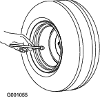
Checking the Tire Pressure
The correct air pressure in the front and rear tires is 83 to 103 kPa (12 to 15 psi).
Important: Maintain pressure in all tires to ensure a good quality of cut and proper machine performance. Do not under-inflate the tires.Check the air pressure in all the tires before operating the machine.
Checking the Torque of the Wheel-Lug Nuts
| Maintenance Service Interval | Maintenance Procedure |
|---|---|
| After the first hour |
|
| After the first 10 hours |
|
| Every 250 hours |
|
Warning
Failure to maintain the proper torque of the wheel nuts could result in failure or loss of a wheel, and may result in personal injury.
Torque the front and rear-wheel nuts to 94 to 122 N·m (70 to 90 ft-lb) at the recommended service intervals.
Adjusting the Height of Cut
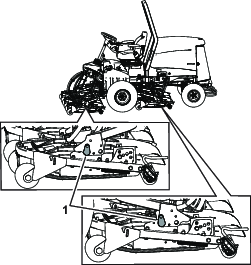
Important: The cutting units often cut approximately 6 mm (1/4 inch) lower than a reel cutting unit with the same bench setting. It may be necessary to set the cutting-unit bench measurement at 6 mm (1/4 inch) above that of reel cutting units cutting in the same area.
Important: Access to the rear cutting units is greatly improved by removing the cutting unit from the machine. Lower the cutting units and remove the cutting units from the frames by removing these bolts and pins shown in Figure 20.
-
Park the machine on a level surface, engage the parking brake, lower the cutting unit to the ground, shut off the engine, and remove the key.
-
Loosen the bolt securing each height-of-cut bracket to the height-of-cut plate (front and each side) as shown in Figure 21.
-
Beginning with front adjustment, remove the bolt.
-
While supporting the chamber, remove the spacer (Figure 21).
-
Move the chamber to the desired height of cut and install a spacer into the designated height-of-cut hole and slot (Figure 22).

-
Position the tapped plate in-line with the spacer.
-
Install the bolt finger-tight.
-
Repeat steps 4 through 7 for each side adjustment.
-
Torque all 3 bolts to 41 N∙m (30 ft-lb). Always tighten the front bolt first.
Note: Adjustments of more than 3.8 cm (1-1/2 inches) may require temporary assembly to an intermediate height to prevent binding (e.g., changing from 3.1 to 7 cm (1-1/4 to 2-3/4 inches) height of cut).
Checking the Interlock Switches
| Maintenance Service Interval | Maintenance Procedure |
|---|---|
| Before each use or daily |
|
Caution
If safety interlock switches are disconnected or damaged, the machine could operate unexpectedly, causing personal injury.
-
Do not tamper with the interlock switches.
-
Check the operation of the interlock switches daily and replace any damaged switches before operating the machine.
Important: If your machine fails any of the interlock switch checks, contact your authorized Toro distributor.
Preparing the Machine
-
Drive the machine slowly to an open area.
-
Lower the cutting units, shut off the engine, and engage the parking brake.
Checking the Traction Pedal Start-Interlock
-
Sit in the operator’s seat.
-
Engage the parking brake.
-
Press the PTO switch to the DISENGAGE position.
-
Press the traction pedal.
-
Rotate the key to the START position.
Note: The engine should not start with the traction pedal pressed.
Checking the PTO-Start Interlock
-
Sit in the operator’s seat.
-
Pull up the PTO switch to the ENGAGE position.
-
Rotate the key to the START position.
Note: The engine should not start with the PTO switch in the ENGAGE position.
Checking the PTO-Run Interlock
-
Sit in the operator’s seat.
-
Press the PTO switch to the DISENGAGE position.
-
Start the engine.
-
Pull up the PTO switch to the ENGAGE position.
-
Lower the cutting units to engage the PTO.
-
Rise from the seat.
Note: The PTO should not run when you are out of the operator’s seat.
Note: Do not allow the cutting units to spin for more than a couple seconds during this test to prevent unnecessary wear.
Checking the Parking Brake and Traction Pedal Run-Interlock
-
Sit in the operator’s seat.
-
Engage the parking brake.
-
Press the PTO switch to the DISENGAGE position.
-
Start the engine.
-
Press the traction pedal.
Note: There should be no machine response when you press the traction pedal while the parking brake is engaged. An advisory message should appear on the InfoCenter.
Checking the Automatic Parking Brake Engage
-
Sit in the operator’s seat.
-
Start the engine.
-
Disengage the parking brake.
-
Rise from the seat.
Note: The red light on the parking-brake switch should illuminate when you are out of the operator’s seat, indicating that the parking brake is on.
Checking the Cutting Unit Lower Disable Interlock
-
Sit in the operator’s seat.
-
Start the engine.
-
Ensure that the cutting units are lifted to the transport position.
-
Rise from the seat.
-
Lower the cutting units.
Note: The cutting units should not lower when you are out of the operator’s seat.
Checking the Blade Stopping Time
| Maintenance Service Interval | Maintenance Procedure |
|---|---|
| Before each use or daily |
|
The blades of the cutting unit should come to a complete stop in approximately 5 seconds after you shut down the cutting-unit-engagement switch.
Note: Make sure that the cutting units are lowered onto a clean section of turf or hard surface to avoid thrown dust and debris.
-
Have a second person stand back from the cutting unit at least 6 m (20 feet) and watch the blades on 1 of the cutting unit.
-
While the cutting units are engaged and spinning at full speed, disengage the PTO switch and record the time it takes for the blades to come to a complete stop.
Note: If this time is greater than 7 seconds, the braking valve needs adjustment. Call your authorized Toro distributor for assistance in making this adjustment.
Selecting a Blade
Standard Combination Sail
This blade was designed to provide excellent lift and dispersion in almost any condition. If more or less lift and discharge velocity is required, consider a different blade.
Attributes: Excellent lift and dispersion in most conditions
Angled Sail (Not CE Compliant)
The blade generally performs best in lower heights of cut—1.9 to 6.4 cm (3/4 to 2-1/2 inches).
Attributes:
-
Discharge remains more even at lower heights of cut.
-
Discharge has less tendency to throw left and thus a cleaner look around bunkers and fairways.
-
Lower power requirement at lower heights and dense turf.
High-Lift Parallel Sail (Not CE Compliant)
The blade generally performs better in the higher heights of cut—7 to 10 cm (2 to 4 inches).
Attributes:
-
More lift and higher discharge velocity
-
Sparse or limp turf is picked up significantly at higher heights of cut
-
Wet or sticky clippings are discharged more efficiently reducing congestion in the cutting unit.
-
Requires more horsepower to run
-
Tends to discharge further left and can tend to windrow at lower heights of cut
Warning
Using a high-lift blade with the mulching baffle could cause the blade to break, resulting in personal injury or death.
Do not use the high-lift blade with the mulching baffle.
Atomic Blade
This blade was designed to provide excellent leaf mulching.
Choosing Accessories
Optional Equipment Configurations
| Angle Sail Blade | High-Lift, Parallel-Sail Blade(Do not use with the mulching baffle) (Not CE Compliant) | Mulching Baffle | Roller Scraper | |
| Grass Cutting: 1.9 to 4.4 cm (3/4 to 1-3/4 inches) height of cut | Recommended in most applications | May work well in light or sparse turf | Has been shown to improve dispersion and after-cut performance on northern grasses that are cut at least 3 times per week and less than 1/3 of the grass blade is removed. Do not use with the high-lift, parallel-sail blade | Use it whenever the rollers build up with grass or large, flat grass clumps of grass are seen. The scrapers may increase clumping in certain applications. |
| Grass Cutting: 5 to 6.4 cm (2 to 2-1/2 inches) height of cut | Recommended for thick or lush turf | Recommended for light or sparse turf | ||
| Grass Cutting: 7 to 10 cm (2-3/4 to 4 inches) height of cut | May work well in lush turf | Recommended in most applications | ||
| Leaf Mulching | Recommended for use with the mulching baffle | Not Allowed | Use with combination sail or angle sail blade only | |
| Pros | Even discharge at lower height of cut; cleaner look around bunkers and fairways; lower power requirements | More lift and higher discharge velocity; sparse or limp turf is picked up at high height of cut; wet or sticky clippings are discharged efficiently | May improve dispersion and appearance in certain grass cutting applications; very good for leaf mulching | Reduces roller buildup in certain applications |
| Cons | Does not lift the grass well in high height-of-cut applications; wet or sticky grass has a tendency to build up in the chamber, leading to poor quality of cut and higher power requirements | Requires more power to run in some applications; tends to windrow at lower height of cut in lush grass; do not use with the mulching baffle | Grass will build up in the chamber if you attempt to remove too much grass with the baffle in place |
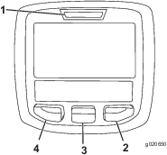
Using the InfoCenter LCD Display
The InfoCenter LCD display shows information about your machine, such as the operating status, various diagnostics and other information about the machine (Figure 23). There is a splash screen and main information screen of the InfoCenter. You can switch between the splash screen and main information screen at any time by pressing any of the InfoCenter buttons and then selecting the appropriate directional arrow.
-
Left Button, Menu Access/Back Button—press this button to access the InfoCenter menus. You can use it to exit any menu that you are currently using.
-
Middle Button—use this button to scroll down menus.
-
Right Button—use this button to open a menu where a right arrow indicates additional content.
-
Beeper—activated when lowering the cutting units or for advisories and faults.
Note: The purpose of each button may change depending on what is required at the time. Each button is labeled with an icon displaying its current function.
| SERVICE DUE | Indicates when scheduled service should be performed |
 | Hours remaining until service |
 | Reset the service hours  |
 | The status of the engine speed (rpm) |
 | Info icon |
 | Maximum traction speed setting |
 | Fast |
 | Slow |
 | The fan is reversed. |
 | The air-intake heater is active. |
 | Raise the left cutting unit. |
 | Raise the center cutting unit. |
 | Raise the right cutting unit. |
 | The operator must sit in the seat. |
 | The parking brake is engaged. |
 | The range is high. |
 | Neutral |
 | Identifies the range as Low |
 | Coolant temperature (°C or °F) |
 | Temperature (hot) |
 | Traction or Traction Pedal |
 | Not allowed |
 | Start the engine. |
 | The PTO is on. |
 | The cruise control is on. |
 | Shut off the engine |
 | Engine |
 | Key switch |
 | Cutting units are lowering |
 | Cutting units are raising |
| PIN code |
 | Hydraulic fluid temperature |
 | CAN bus |
 | InfoCenter |
 | Bad or failed |
 | Center |
 | Right |
 | Left |
 | Bulb |
 | Output of TEC controller or control wire in harness |
 | Over the allowed range |
 | Under the allowed range |
| / | Out of range |
 | Switch |
 | Operator must release switch |
 | Operator should change to indicated state |
 | Warm-up mode |
| Symbols are often combined to form sentences. Some examples are shown below. | |
 | Operator should put machine in neutral |
 | Engine start is denied |
 | Engine shutdown |
 | Engine coolant is too hot |
 | Hydraulic fluid is too hot |
 | DPF ash accumulation notification. Refer to Servicing the Diesel Particulate Filter (DPF) in the maintenance section for details |
 | Reset-standby regeneration request |
| Parked or recovery regeneration request | |
 | A parked or recovery regeneration is processing. |
 | High exhaust temperature |
 | NOx control diagnosis malfunction; drive the machine back to the shop and contact your authorized Toro distributor (software version U and later). |
 | The power take-off is disabled. |
 | Sit down or engage the parking brake. |
Accessible
only by entering PIN
Using the Menus
To access the InfoCenter menu system, press the menu access button while at the main screen. This brings you to the main menu. Refer to the following tables for a synopsis of the options available from the menus:
| Main Menu—Menu Item | Description |
| Faults | Contains a list of the recent machine faults. Refer to the Service Manual or your authorized Toro distributor for more information on the Faults menu and the information contained there. |
| Service | Contains information on the machine such as hours of use, counters, and other similar numbers |
| Diagnostics | Displays the state of each machine switch, sensor, and control output. You can use this to troubleshoot certain issues as it quickly tells you which machine controls are ON and which are OFF. |
| Settings | Allows you to customize and modify configuration variables on the InfoCenter display. |
| About | Lists the model number, serial number, and software version of your machine. |
| Service—Menu Item | Description |
| Hours | Lists the total number of hours that the machine, engine, and PTO have been on, as well as the number of hours the machine has been transported and service due |
| Counts | Lists numerous counts the machine has experienced. |
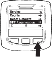
| DPF Regeneration | The diesel particulate filter regeneration option and DPF submenus |
| Inhibit Regen | Use to control reset regeneration |
| Parked Regen | Use to initiate a parked regeneration |
| Last Regen | Lists the number hours since the last reset, parked, or recovery regeneration |
| Recover Regen | Use to initiate a recovery regeneration |
| Diagnostics—Menu Item | Description |
| Cutting Units | Indicates the inputs, qualifiers, and outputs for raising and lowering the cutting units |
| Hi/Low Range | Indicates the inputs, qualifiers, and outputs for driving in transport mode |
| PTO | Indicates the inputs, qualifiers, and outputs for enabling the PTO circuit |
| Engine Run | Indicates the inputs, qualifiers, and outputs for starting the engine |
| Settings—Menu Item | Description |
| Units | Controls the units used on the InfoCenter (English or Metric) |
| Language | Controls the language used on the InfoCenter* |
| LCD Backlight | Controls the brightness of the LCD display |
| LCD Contrast | Controls the contrast of the LCD display |
| Protected Menus | Allows a person authorized by your company with the PIN code to access protected menus |
| Protect Settings | Allows the ability to change the settings in the protected settings |
| Acceleration | Low, Medium, and High settings control how quickly the traction speed reacts when you move the traction pedal. |
| Mow Speed | Controls the maximum speed while in mow (low range) |
| Trans. Speed | Controls the maximum speed while in transport (high range) |
| Smart Power | Turns Smart Power on and off |
| Counterbalance | Controls the amount of counterbalance applied by the cutting units |
Protected
under Protected Menus—accessible only by entering PIN
| About—Menu Item | Description |
| Model | Lists the model number of the machine |
| SN | Lists the serial number of the machine |
| Machine Controller Revision | Lists the software revision of the master controller |
| InfoCenter Revision | Lists the software revision of the InfoCenter |
| CAN Bus | Lists the machine communication bus status |
Protected Menus
There are operating configuration settings that are adjustable within the Settings Menu of the InfoCenter. To lock these settings, use the Protected Menu.
Note: At the time of delivery, the initial password code is programmed by your distributor.
Accessing Protected Menus
Note: The factory default PIN code for you machine is either 0000 or 1234.If you changed the PIN code and forgot the code, contact your authorized Toro distributor for assistance.
-
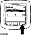
From the MAIN MENU, use the center button to scroll down to the SETTINGS MENU and press the right button (Figure 24).
-
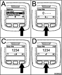
In the SETTINGS MENU, use the center button to scroll down to the PROTECTED MENU and press the right button (Figure 25A).
-
To enter the PIN code, press the center button until the correct first digit appears, then press the right button to move on to the next digit (Figure 25B and Figure 25C). Repeat this step until the last digit is entered and press the right button once more.
-
Press the middle button to enter the PIN code (Figure 25D).
Wait until the red indicator light of the InfoCenter illuminates.
Note: If the InfoCenter accepts the PIN code and the protected menu is unlocked, the word “PIN” displays in the upper right corner of the screen.
Note: Rotate the key switch to the OFF position and then to the ON position locks the protected menu.
You can view and change the settings in the Protected Menu. Once you access the Protected Menu, scroll down to Protect Settings option. Use the right button to change the setting. Setting the Protect Settings to OFF allows you to view and change the settings in the Protected Menu without entering the PIN code. Setting the Protect Settings to ON hides the protected options and requires you to enter the PIN code to change the setting in the Protected Menu. After you set the PIN code, rotate the key switch OFF and back to the ON position to enable and save this feature.
Viewing and Changing the Protected Menu Settings
-
In the Protected Menu, scroll down to Protect Settings.
-
To view and change the settings without entering a PIN code , use the right button to change the Protect Settings to OFF.
-
To view and change the settings with a PIN code, use the left button to change the Protect Settings to ON, set the PIN code, and turn the key in the ignition switch to the OFF position and then to the ON position.
Setting the Maximum Allowed Mow Speed
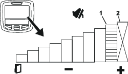
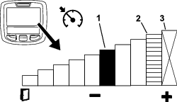
The selected setting is displayed as an X on the traction-speed bar graph along with the cruise control and pedal stop settings. An X in a bar shows you that the maximum speed is limited by the supervisor (Figure 28 or Figure 30).
Note: This setting is retained in memory and applied to the traction speed until you change it.
-
In the Settings Menu, scroll down to Mow Speed and press the right button.
-
Use the right button to increase the maximum mow speed in 0.8 km/h (0.5 mph) increments between 1.6 and 12.9 km/h (1 and 8 mph).
-
Use the center button to decrease the maximum mow speed in 0.8 km/h (0.5 mph) increments between 1.6 and 12.9 km/h (1 and 8 mph).
-
Press the left button to exit.
Setting the Maximum Allowed Transport Speed
The selected setting is displayed as an X on the traction-speed bar graph along with the cruise control and pedal stop settings. An X in a bar shows you that the maximum speed is limited by the supervisor (Figure 28 or Figure 30).
Note: This setting is retained in memory and applied to the traction speed until you change it.
-
In the Settings Menu, scroll down to Transport Speed and press the right button.
-
Use the right button to increase the maximum transport speed in 0.5 mph increments between 5 and 10 mph.
-
Use the center button to decrease the maximum transport speed in 0.5 mph increments between 5 and 10 mph.
-
Press the left button to exit.
Turning the Smart Power ON/OFF
-
In the settings menu, scroll down to Smart Power.
-
Press the right button to switch between ON and OFF.
-
Press the left button to exit.
Setting the Counterbalance
-
In the Settings Menu, scroll down to Counterbalance.
-
Press the right button to select counterbalance and change between the LOW, MEDIUM, and HIGH settings.
Setting the Acceleration Mode
-
In the Settings Menu, scroll down to Acceleration.
-
Press the right button to switch between LOW, MEDIUM, and HIGH.
-
Press the left button to exit.
Setting the Service Due Timer
The service due timer resets the service due hours after a scheduled maintenance procedure is performed.
-
In the Settings Menu, use the center button to scroll down to the PROTECTED MENU and press the right button.
-
Enter PIN; refer to Accessing Protected Menus on the Operator’s Manual for your machine.
-
In the Service Menu, navigate to the HOURS MENU.
-
Scroll down to the service symbol
.Note: If service is currently due, the first icon shows NOW.
-
Below the first icon is the service interval item
(time interval, e.g. 250,
500, etc.)Note: Service interval is a protected menu item.
-
Highlight the service interval and press the right button.
-
When the new screen appears, confirm RESET SERVICE HOURS—ARE YOU SURE?
-
Select YES(center button) or NO (left button).
-
After you select YES the interval screen clears, and reverts back to the Service Hours selections.
Understanding the Diagnostic Light
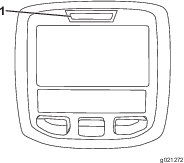
The machine is equipped with a diagnostic light, which indicates if the machine detects a malfunction. The diagnostic light is located on the InfoCenter, above the display screen (Figure 26). When the machine functions properly and the key switch is moved to the ON/RUN position, the diagnostic light turns on briefly to indicate that the light is working properly. When a machine advisory message displays, the light illuminates when the message is present. When a fault message is displayed, the light blinks until the fault is resolved.
Checking the Hydrostatic Braking Distance
This machine will dynamically brake and stop when you return the traction pedal to neutral.
Note: For smooth deceleration, use your foot to slowly control the traction pedal back to neutral. Do not take your foot off the pedal and allow it to snap back to the neutral position unless you intend to stop quickly.
The machine should come to a complete stop in approximately 3.7 m (12 ft) from the maximum transport speed of 10 mph.
-
On flat, dry pavement, mark out the start and end of 3.7 m (12 ft).
-
Drive the machine at the maximum transport speed of 16 km/h (10 mph) and remove your foot at the start of the 3.7 m (12 ft).
-
Check if the machine stops within 0.6 m (2 ft) of the end mark (3.7 m or 12 ft).
-
Contact your Toro distributor if the stopping distance of the machine is not within 0.6 m (2 ft) of this distance.
Understanding Reverse Speeds
Transport Reverse Speed
-
If the maximum transport speed set by the supervisor is above 8.0 km/h (5.0 mph), the maximum reverse speed is 8.0 km/h (5.0 mph).
-
If the maximum transport speed set by the supervisor is at or below 8.0 km/h (5.0 mph), maximum reverse speed is equal to the transport speed set by the supervisor.
Mowing Reverse Speed
-
If the maximum mow speed set by the supervisor is above 6.4 km/h (4.0 mph), the maximum reverse speed is 6.4 km/h (4.0 mph).
-
If the maximum mow speed set by the supervisor is at or below 6.4 km/h (4.0 mph), maximum reverse speed is equal to the transport speed set by the supervisor.
Understanding Displayed Traction Speeds
This machine displays estimated traction speeds in kilometers per hour (km/h) or miles per hour (mph).
-
The instantaneous speed is displayed in the upper left-hand corner of the cruise control and virtual pedal stop screens.
-
The traction speeds are estimated, and calibrated to be most accurate at 8.0 km/h (5.0 mph) while mowing. Displayed speeds are accurate when it is 0.8 km/h (0.5 mph) above or below the display speed while driving on dry, flat pavement.
-
Contact your authorized Toro distributor if the machine's observed speeds deviate more than 2.4 km/h (1.5 mph) from the displayed speeds.
Understanding the Warm-Up Mode
When starting the machine in cold weather, warm-up mode limits the engine speed to low idle for a short period after the engine is started, preventing potential component damage from operating the machine with cold oil.
A snowflake icon on the InfoCenter screen denotes when warm-up
mode is active. Do not operate the machine until after the warm-up
period.
During Operation
During Operation Safety
General Safety
-
The owner/operator can prevent and is responsible for accidents that may cause personal injury or property damage.
-
Wear appropriate clothing, including eye protection; long pants; substantial, slip-resistant footwear; and hearing protection. Tie back long hair and do not wear loose clothing or loose jewelry.
-
Do not operate the machine while ill, tired, or under the influence of alcohol or drugs.
-
Use your full attention while operating the machine. Do not engage in any activity that causes distractions; otherwise, injury or property damage may occur.
-
Before you start the engine, ensure that all drives are in neutral, the parking brake is engaged, and you are in the operating position.
-
Do not carry passengers on the machine and keep bystanders and children out of the operating area.
-
Operate the machine only in good visibility to avoid holes or hidden hazards.
-
Avoid mowing on wet grass. Reduced traction could cause the machine to slide.
-
Keep your hands and feet away from rotating parts. Keep clear of the discharge opening.
-
Look behind and down before backing up to be sure of a clear path.
-
Use care when approaching blind corners, shrubs, trees, or other objects that may obscure your vision.
-
Stop the blades whenever you are not mowing.
-
Stop the machine, remove the key, and wait for all moving parts to stop before inspecting the attachment after striking an object or if there is an abnormal vibration in the machine. Make all necessary repairs before resuming operation.
-
Slow down and use caution when making turns and crossing roads and sidewalks with the machine. Always yield the right-of-way.
-
Disengage the drive to the cutting unit, shut off the engine, remove the key, and wait for all movement to stop before adjusting the height of cut (unless you can adjust it from the operating position).
-
Operate the engine only in well-ventilated areas. Exhaust gases contain carbon monoxide, which is lethal if inhaled.
-
Never leave a running machine unattended.
-
Before you leave the operator’s position, do the following:
-
Park the machine on a level surface.
-
Disengage the power takeoff and lower the attachments.
-
Engage the parking brake.
-
Shut off the engine and remove the key.
-
Wait for all movement to stop.
-
-
Operate the machine only in good visibility. Do not operate the machine when there is the risk of lightning.
-
Do not use the machine as a towing vehicle.
-
Use accessories, attachments, and replacement parts approved by Toro only.
-
Use the cruise control (if equipped) only when you can operate the machine in an open, flat area that is free from obstacles and where the machine can move at a constant speed without interruption.
Rollover Protection System (ROPS) Safety
-
The ROPS is an integral and effective safety device.
-
Do not remove any of the ROPS components from the machine.
-
Ensure that the seat belt is attached to the machine.
-
Pull the belt strap over your lap and connect the belt to the buckle on the other side of the seat.
-
To disconnect the seat belt, hold the belt, press the buckle button to release the belt, and guide the belt into the auto-retract opening. Ensure that you can release the belt quickly in an emergency.
-
Check carefully for overhead obstructions and do not contact them.
-
Keep the ROPS in safe operating condition by thoroughly inspecting it periodically for damage and keeping all the mounting fasteners tight.
-
Replace damaged ROPS components. Do not repair or alter them.
Additional ROPS Safety for Machines with a Cab or a Fixed Roll Bar
-
A cab installed by Toro is a roll bar.
-
Always wear your seat belt.
Slope Safety
-
Slopes are a major factor related to loss of control and rollover accidents, which can result in severe injury or death. You are responsible for safe slope operation. Operating the machine on any slope requires extra caution.
-
Evaluate the site conditions to determine if the slope is safe for machine operation, including surveying the site. Always use common sense and good judgment when performing this survey.
-
Review the slope instructions listed below for operating the machine on slopes and to determine whether you can operate the machine in the conditions on that day and at that site. Changes in the terrain can result in a change in slope operation for the machine.
-
Avoid starting, stopping, or turning the machine on slopes. Avoid making sudden changes in speed or direction. Make turns slowly and gradually.
-
Do not operate a machine under any conditions where traction, steering, or stability is in question.
-
Remove or mark obstructions such as ditches, holes, ruts, bumps, rocks, or other hidden hazards. Tall grass can hide obstructions. Uneven terrain could overturn the machine.
-
Be aware that operating the machine on wet grass, across slopes, or downhill may cause the machine to lose traction. Loss of traction to the drive wheels may result in sliding and a loss of braking and steering.
-
Use extreme caution when operating the machine near drop-offs, ditches, embankments, water hazards, or other hazards. The machine could suddenly roll over if a wheel goes over the edge or the edge caves in. Establish a safety area between the machine and any hazard.
-
Identify hazards at the base of the slope. If there are hazards, mow the slope with a pedestrian-controlled machine.
-
If possible, keep the cutting unit(s) lowered to the ground while operating on slopes. Raising the cutting unit(s) while operating on slopes can cause the machine to become unstable.
-
Use extreme caution with grass-collection systems or other attachments. These can change the stability of the machine and cause a loss of control.
Understanding the Operating Characteristics of the Machine
-
This machine has an automotive-style throttle that is controlled by the traction pedal.
-
This machine does not have a separate throttle switch or throttle lever.
-
When you remove your foot from the traction pedal, the machine dynamically brakes to a stop.
-
The pedal controls are optimized to provide a reactive yet stable response, allowing you to maintain consistent control over rough terrain, while still allowing for quick, smooth braking.
-
While transporting, the traction pedal will operate similar to a car and change the engine and traction speed dependent on the traction pedal position.
-
When mowing, the engine speed will automatically raise to high idle.
-
If the engine is at low idle, performing a function like lifting the cutting units or pressing the traction pedal raises the engine speed to a minimum working speed, providing enough power to efficiently perform the function.
-
Limit the machine idle time as recommended for diesel particulate filter (DPF) regeneration. Shut of the machine to prevent extended idling time.
-
The maximum speeds set in the PIN protected menu settings are set by the supervisor to limit the machine’s maximum traction speed.
-
The achievable traction pedal use, cruise control, and pedal stop traction speeds are all limited by the maximum speeds set in the PIN protected menu.
Operating the Machine
-
If an obstacle is in the way, lift the cutting units or mow around it.
-
When transporting the machine between work areas, shut off the PTO, and raise the cutting units to the fully upward position. This allows the traction pedal to operate like a car.
-
Always drive slowly in rough areas.
-
Never shut off the machine while driving the machine.
Practice Operating the Machine
-
To get familiar with the features of the machine, practice operating the machine.
-
Lift the cutting units, disengage the parking brake, press the forward traction pedal, and carefully drive to an open area.
-
Practice driving the machine, because it has a hydrostatic transmission and its features can differ from other turf-maintenance machines.
-
Practice moving forward and reverse, and starting and stopping the machine. To stop the machine, remove your foot from the traction pedal and let it return to NEUTRAL.
Note: When going downhill in the machine, you may need to use the reverse pedal to stop.
-
Remove your foot from the traction pedal to stop quickly.
-
Practice driving around obstacles with the cutting units up and down. Be careful when driving between narrow objects so that you do not damage the machine or cutting units.
Using the Traction Pedal
This pedal controls the forward and reverse speed of the machine and the dynamic braking when you return it to neutral.
-
This machine is equipped with an automotive-style throttle—the engine speed and the machine speed respond to the pedal movement.
-
While transporting, the traction pedal will operate similar to a car and change the engine and traction speed dependent on the traction pedal position.
-
While mowing, the engine automatically raises to high idle to optimize mowing performance, and the traction pedal only controls traction speed.
-
The further you push the pedal forward or reverse, the faster the machine moves.
-
To control the machine to a smooth stop while transporting or mowing, use your foot to return the traction pedal to neutral at your desired rate.
-
To engage maximum braking, remove your foot from the traction pedal, allowing it to return to neutral. The machine dynamically brakes to a stop.
This traction system allows you to customize the acceleration settings for operator comfort and course conditions. Refer to Understanding the Acceleration Mode for changing the settings.

Using the Virtual Pedal Stop (VPS) Feature
The virtual pedal stop (VPS) feature allows you to temporarily set a maximum traction speed that is less than the password-protected supervisor maximum traction speed.
To temporarily set the maximum speed of the machine, press the traction pedal fully forward (Figure 27). You can set a separate speed for the mow range and transport range (Figure 28).
-
To access this feature, select the InfoCenter middle button from the main screen (Figure 28).
Note: This feature reverts back to the supervisor maximum speed settings when the key is switched off.
-
This feature allows you to customize the speed settings for your comfort level, or to customize the speed settings to fit the application.
Whenever the max traction speed is changed via the supervisor max speed settings or Virtual Pedal Stop, the traction pedal is automatically reprogrammed to use the full pedal stroke between neutral and the new max speed. This means the operator gains more precise control of the traction speed at lower maximum speed settings.
Tips for Using Virtual Pedal Stop (VPS)
-
Set the max speed temporarily lower for mowing the cleanup pass on the fairway.
-
Set the max speed temporarily lower for improved control operating in or near the maintenance shop.
-
Set the max speed temporarily lower for improved control loading the machine onto a trailer.
Operating the Cruise Control
Setting the Cruise Control
The cruise-control switch locks in the cruise control to maintain the desired ground speed. Pressing the rear of the switch turns the cruise control off, the middle position of the switch enables the cruise-control function, and the front of the switch sets the desired ground speed.
After the cruise control switch is enabled and the speed is set (Figure 29), use the InfoCenter to adjust the speed setting of the cruise control (Figure 23 and Figure 30).
To disengage the cruise control use the following:
-
When in transport range, press the reverse traction pedal, engage the parking brake, or press the cruise control switch to the OFF position.
-
When in mow range, press the reverse traction pedal, engage the parking brake, disengage the PTO, or press the cruise control switch to the OFF position.
Note: Disengaging cruise control results in the machine dynamically braking to a stop. If you would like to disengage cruise control but continue driving, press the traction pedal for a smooth transition from cruise control to manual speed control.
Adjusting the Cruise Control Speed
Tips for Using the Cruise Control
-
Set a cruising speed for long distances without many obstacles.
-
On rough terrain, use the InfoCenter to control the speed.
-
Use the cruise control for turnarounds as follows:
-
While mowing, set a safe, comfortable speed for turning around at the end of mowing passes.
-
Press the traction pedal to increase the speed for mowing during the mowing pass.
-
Take your foot off the pedal when turning around for the next mowing pass.
-
The machine will slow down to the low cruise control setting, allowing you to make an efficient turnaround at a constant speed.
-
After turning around, use the traction pedal to increase the machine speed back up for the next mowing pass.
-
Understanding the Acceleration Mode
This feature determines how quickly the machine changes traction speed when the traction pedal is not in the NEUTRAL position.
Note: If you take your foot off the traction pedal, allowing it to return to the NEUTRAL position while the machine is moving, the braking profile is engaged. The braking profile is always the same and cannot be customized by the acceleration mode feature.
Enter the protected menus in the InfoCenter to change the acceleration mode. The acceleration mode has the following 3 positions:
-
Low—least aggressive acceleration and deceleration
-
Medium (default)—medium acceleration and deceleration
-
High—most aggressive acceleration and deceleration
Understanding Counterbalance
The counterbalance system maintains hydraulic back pressure on the cutting-unit lift cylinders. The counterbalance system monitors the real-time traction pressure, dynamically changing the lift-cylinder back pressure to optimize traction capability and after-cut appearance. The counterbalance pressure has been set at the factory to an optimal balance of after-cut appearance and traction capability in most turf conditions. Decreasing the counterbalance setting can produce a more stable cutting unit but can decrease the traction capability. Increasing the counterbalance setting can increase the traction capability, but may reduce the quality of the after-cut appearance; refer to Accessing Protected Menus.
The customizable counterbalance setting controls are as follows:
-
Low—the most amount of weight on cutting units and the lowest weight on the drive wheels
-
Medium—medium weight on cutting units and the drive wheels
-
High—the least amount of weight on cutting units and the highest weight on machine drive wheels
Changing the Counterbalance Settings
You can change the amount of required cutting-unit counterbalance (upward lift) to meet your current mowing conditions.
-
Park the machine on a level surface, lower the cutting decks, turn the key in the switch to the OFF position, and engage the parking brake.
-
Turn the key in the switch to the RUN position.
-
In the InfoCenter Settings Menu, scroll down to Counterbalance.
-
Press the right button to select counterbalance and change between the low, medium, and high settings.
Note: Once the adjustment has been completed, move the machine to a test area and operate the machine with the new setting. The new counterbalanced setting may change the effective height of cut.
Understanding Toro Smart Power™
With Smart Power, the operator does not have to listen to the engine speed in heavy load conditions. Smart Power prevents the engine from bogging down in heavy cutting conditions by automatically controlling the machine speed and optimizing cutting performance.
Note: By default, the Smart Power feature is ON.
Starting the Engine
Important: The fuel system automatically bleeds itself before starting the engine if you are starting the engine for the first time, the engine has shut off due to lack of fuel, or you have performed maintenance on the fuel system.
-
Sit on the seat, keep your foot off the traction pedal so that it is in NEUTRAL, engage the parking brake, and ensure that the PTO switch is in the DISENGAGED position.
-
Turn the key in the switch to the RUN position.
-
When the glow indicator dims, turn the key in the switch to the START position. Release the key immediately when the engine starts and allow it to return to the RUN position.
-
Run the engine at low idle speed until it warms up.
Shutting Off the Engine
-
Move all controls to NEUTRAL, engage the parking brake, and allow the engine to reach low idle speed.
Important: Allow the engine to idle for 5 minutes before shutting it off after a full load operation. Failure to do so may engine components.
-
Turn the key in the switch to the OFF position and remove the key.
Cutting Grass with the Machine
-
Start the engine, disengage the brake, disengage the PTO switch, and raise the cutting units.
-
Using the traction pedal like an accelerator pedal on a car, drive the machine to the mowing area.
-
Pull the PTO switch to the ENGAGE position.
-
Start driving the machine and lower the cutting units only when all cutting units are over the mowing area.
-
Begin mowing the area.
-
When you complete a mowing pass, tap the lower control lever rearward to lift the cutting units before leaving the mowing area.
-
Perform a tear-shaped turn to quickly line up for your next pass.
-
Press the lower control lever to automatically lower all cutting units in the mowing area and continue mowing.
Diesel Particulate Filter Regeneration
The diesel particulate filter (DPF) is part of the exhaust system. The diesel-oxidation catalyst of the DPF reduces harmful gasses and the soot filter removes soot from the engine exhaust.
The DPF regeneration process uses heat from the engine exhaust to incinerate the soot accumulated on the soot filter, converting the soot to ash, and clears the channels of the soot filter so that filtered engine exhaust flows out the DPF.
The engine computer monitors the accumulation of soot by measuring the back pressure in the DPF. If the back pressure is too high, soot is not incinerating in the soot filter through normal engine operation. To keep the DPF clear of soot, remember the following:
-
Passive regeneration occurs continuously while the engine is running—run the engine at full engine speed when possible to promote DPF regeneration.
-
If the back pressure in the DPF is too high or a reset regeneration has not occurred for 100 hours, the engine computer signals you through the InfoCenter when reset regeneration is running.
-
Allow the reset regeneration process to complete before shutting off the engine.
Operate and maintain your machine with the function of the DPF in mind. Engine load at high idle (full throttle) engine speed generally produces adequate exhaust temperature for DPF regeneration.
Important: Minimize the amount of time that you idle the engine or operate the engine at low-engine speed to help reduce the accumulation of soot in the soot filter.
DPF Soot Accumulation
-
Over time, the diesel particulate filter accumulates soot in the soot filter. The computer for the engine monitors the soot level in the DPF.
-
When enough soot accumulates, the computer informs you that it is time to regenerate the DPF.
-
DPF regeneration is a process that heats the DPF to convert the soot to ash.
-
In addition to the warning messages, the computer reduces the power produced by the engine at different soot-accumulation levels.
| Indication Level | Fault Code | Engine Power Rating | Recommended Action |
| Level 1: Engine Warning |
 | The computer de-rates the engine power to 85%. | Perform a parked regeneration as soon as possible; refer to Servicing the Diesel-Oxidation Catalyst (DOC) and the Soot Filter. |
| Level 2: Engine Warning |
 | The computer de-rates the engine power to 50%. | Perform a recovery regeneration as soon as possible; refer to Servicing the Diesel-Oxidation Catalyst (DOC) and the Soot Filter. |
DPF Ash Accumulation
-
The lighter ash is discharged through the exhaust system; the heavier ash collects in the soot filter.
-
Ash is a residue of the regeneration process. Over time, the diesel particulate filter accumulates ash that does not discharge with the engine exhaust.
-
The computer for the engine calculates the amount of ash accumulated in the DPF.
-
When enough ash accumulates, the engine computer sends information to the InfoCenter in the form of an engine fault to indicate the accumulation of ash in the DPF.
-
The fault messages indicate that it is time to service the DPF.
-
In addition to the warnings, the computer reduces the power produced by the engine at different ash-accumulation levels.
| Indication Level | Fault Code | Engine Speed Reduction | Engine Power Rating | Recommended Action |
|---|---|---|---|---|
| Level 1: Engine Warning |
 | None | The computer de-rates the engine power to 85%. | Service the DPF; refer to Servicing the Diesel-Oxidation Catalyst (DOC) and the Soot Filter |
| Level 2: Engine Warning |
| None | The computer de-rates the engine power to 50%. | Service the DPF; refer to Servicing the Diesel-Oxidation Catalyst (DOC) and the Soot Filter |
Types of Diesel Particulate Filter Regeneration
| Type of Regeneration | Conditions that cause DPF regeneration | DPF description of operation |
|---|---|---|
| Passive | Occurs during normal operation of the machine at high-engine speed or high-engine load | • The InfoCenter does not display an icon indicating passive regeneration. |
| • During passive regeneration, the DPF processes high-heat exhaust gasses, oxidizing harmful emissions, and burning soot to ash. | ||
| Refer to Passive DPF Regeneration. | ||
| Assist | Occurs because of low-engine speed, low-engine load, or after the computer detects the DPF is becoming obstructed with soot | • The InfoCenter does not display an icon indicating assist regeneration. |
| • During assist regeneration, the engine computer adjusts the engine settings to raise the exhaust temperature. | ||
| Refer to Assist DPF Regeneration. | ||
| Reset | Occurs every 100 hours | • When the high exhaust-temperature icon  is displayed in the InfoCenter,
a regeneration is in progress. is displayed in the InfoCenter,
a regeneration is in progress. |
| Also occurs after assist regeneration only if the computer detects that assist regeneration did not sufficiently reduce the soot level | ||
| • During reset regeneration, the engine computer adjusts the engine settings to raise the exhaust temperature. | ||
| Refer to Reset Regeneration. |
| Type of Regeneration | Conditions that cause DPF regeneration | DPF description of operation |
|---|---|---|
| Parked | Occurs because the computer detects back pressure in the DPF due to soot buildup | • When the reset-standby/parked
or recovery regeneration icon  or ADVISORY #188 displays
in the InfoCenter, a regeneration is requested. or ADVISORY #188 displays
in the InfoCenter, a regeneration is requested. |
| Also occurs because the operator initiates a parked regeneration | ||
| May occur because you set the InfoCenter to inhibit reset regeneration and continued operating the machine, adding more soot when the DPF already needs a reset regeneration | • Perform the parked regeneration as soon as possible to avoid needing a recovery regeneration. | |
| May result from using the incorrect fuel or engine oil | • A parked regeneration requires 30 to 60 minutes to complete. | |
| • You must have at least a 1/4 tank of fuel in the tank. | ||
| • You must park the machine to perform a parked regeneration. | ||
| Refer to Parked or Recovery Regeneration. | ||
| Recovery | Occurs because the operator ignored requests for a parked regeneration and continued operating the machine, adding more soot to the DPF | • When the reset-standby/parked or recovery
regeneration icon or ADVISORY #190 displays
in the InfoCenter, a recovery regeneration is requested. |
| • A recovery regeneration requires up to 3 hours to complete. | ||
| • You must have at least a 1/2 tank of fuel in the machine. | ||
| • You must park the machine to perform a recovery regeneration. | ||
| Refer to Parked or Recovery Regeneration. |
Accessing the DPF Regeneration Menus
Accessing the DPF Regeneration Menus
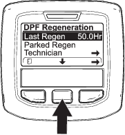
Time Since Last Regeneration
Access the DPF Regeneration menu, press the center button to scroll down to the LAST REGEN field (Figure 36).
Use the LAST REGEN field to determine how many hours you have run the engine since the last reset, parked, or recovery regeneration.
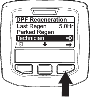
Technician Menu
Important: For operating convenience, you may decide to perform a parked regeneration before the soot load reaches 100%, provided the engine has run more than 50 hours since the last successful reset, parked, or recovery regeneration.
Use the technician menu to view the current state of engine regeneration control and view the reported soot level.
Access the DPF Regeneration menu, press the center button to scroll down to the TECHNICIAN option, and press the right button to select the Technician entry (Figure 37).
-
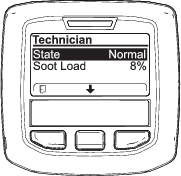
Use the DPF operation table to understand the current state of DPF operation (Figure 38).
.
DPF Operation Table
State Description Normal The DPF is in normal-operating mode—passive regeneration. Assist Regen The engine computer is performing an assist regeneration. Reset Stby The engine computer is trying to run a reset regeneration, but 1 of the following conditions prevents regeneration: The regen inhibit setting is set to ON. The exhaust temperature is too low for regeneration. Reset Regen The engine computer is running a reset regeneration. Parked Stby The engine computer is requesting that you run a parked regeneration. Parked Regen You initiated a parked regeneration request and the engine computer is processing the regeneration. Recov. Stby The engine computer is requesting that you run a recovery regeneration. Recov. Regen You initiated a recovery regeneration request and the engine computer is processing the regeneration. -
View the soot load which is measured as the percentage of soot in the DPF (Figure 39); refer to the soot-load table.
Note: The soot load value varies as the machine is operated and DPF regeneration occurs.

Soot-Load Table
Important Soot Load Values Regeneration State 0% to 5% Minimum soot load range 78% The engine computer performs an assist regeneration. 100% The engine computer automatically requests a parked regeneration. 122% The engine computer automatically requests a recovery regeneration.
Passive DPF Regeneration
-
Passive regeneration occurs as part of normal engine operation.
-
While operating the machine, run the engine at full-engine speed and high load when possible to promote DPF regeneration.
Assist DPF Regeneration
-
The engine computer adjusts engine settings to raise the exhaust temperature.
-
While operating the machine, run the engine at full engine speed and high load when possible to promote DPF regeneration.
Reset Regeneration
Caution
The exhaust temperature is hot (approximately 600°C (1,112°F) during DPF regeneration. Hot exhaust gas can harm you or other people.
-
Never operate the engine in an enclosed area.
-
Make sure that there are no flammable materials around the exhaust system.
-
Never touch a hot exhaust system component.
-
Never stand near or around the exhaust pipe of the machine.
-
The high exhaust-temperature icon
displays in the InfoCenter
(Figure 40). -
The engine computer adjusts engine settings to raise the exhaust temperature.
Important: The high exhaust-temperature icon indicates that the exhaust temperature discharged from of your machine may be hotter than during regular operation.
-
While operating the machine, run the engine at full engine speed and high load when possible to promote DPF regeneration.
-
The icon displays in the InfoCenter while the reset regeneration is processing.
-
Whenever possible, do not shut off the engine or reduce engine speed while the reset regeneration is processing.
Important: Whenever possible, allow the machine to complete the reset regeneration process before shutting off the engine.
Periodic Reset Regeneration
If the engine has not completed a successful Reset, Parked, or Recovery regeneration in the previous 100 hours of engine operation, the engine computer will attempt to perform a reset regeneration.
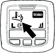
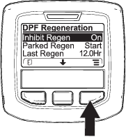
Setting the Inhibit Regen
Reset Regeneration Only

Note: If you set the InfoCenter to inhibit regeneration, the InfoCenter displays ADVISORY #185 (Figure 41) every 15 minutes while the engine requests a reset regeneration.
A reset regeneration produces the elevated engine exhaust. If you are operating the machine around trees, brush, tall grass, or other temperature-sensitive plants or materials, you can use the Inhibit Regen setting to prevent the engine computer from performing a reset regeneration.
Important: When you shut off the engine and start it again, the inhibit regen setting defaults to OFF.

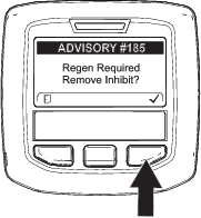
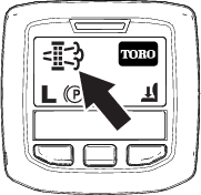
Allowing a Reset Regeneration
The InfoCenter displays the high exhaust-temperature icon when the reset regeneration
is in process.
Note: If INHIBIT REGEN is set to ON, the InfoCenter displays ADVISORY #185 (Figure 44). Press button 3 to set inhibit regeneration setting to OFF and continue with the reset regeneration.
Note: If the InfoCenter displays ADVISORY #186 (Figure 45), set the engine to full throttle (high idle) to allow the reset regeneration to continue.

Note: When the reset regeneration completes, the high exhaust-temperature disappears from the InfoCenter
screen.
Parked or Recovery Regeneration
-
When the engine computer requests either a parked regeneration or a recovery regeneration, the regeneration request icon (Figure 46) displays in the InfoCenter.
-
The machine does not automatically perform a parked regeneration or a recovery regeneration, you must run the regeneration through the InfoCenter.
Parked Regeneration Messages
When a parked regeneration is requested by the engine computer the following messages display in the InfoCenter:
-
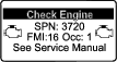
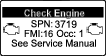
Engine warning SPN 3720, FMI 16 (Figure 47)
-
Parked regeneration required ADVISORY #188 (Figure 48)
Note: Advisory #188 displays every 15 minutes.

-
If you do not perform a parked regeneration within 2 hours, the InfoCenter displays parked regeneration required—power takeoff disabled ADVISORY #189 (Figure 49).
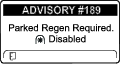
Important: Perform a parked regeneration to restore the PTO function; refer to Preparing to Perform a Parked or Recovery Regeneration and Performing a Parked or Recovery Regeneration.
Note: The Home screen displays the PTO disabled Icon (Figure 50).
Recovery Regeneration Messages
When a recovery regeneration is requested by the engine computer, the following messages display in the InfoCenter:
-
Engine warning SPN 3719, FMI: 0 (Figure 51)
-
Engine warning SPN 522574, FMI: 0 (Figure 52)
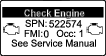
-
Recovery regeneration required—power takeoff disabled ADVISORY #190 (Figure 53)
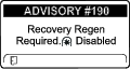
Important: Perform a recovery regeneration to restore the PTO function; refer to Preparing to Perform a Parked or Recovery Regeneration and Performing a Parked or Recovery Regeneration.
Note: The Home screen displays the PTO disabled Icon; refer to Figure 50 in Parked Regeneration Messages.
DPF Status-Limitation
-
If the engine computer requests a recovery regeneration or is processing a recovery regeneration and you scroll down to the PARKED REGEN option, parked regeneration locks and the lock icon (Figure 54) appears in the lower right corner of the InfoCenter.
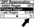
-
If the engine computer has not requested a recovery regeneration and you scroll down to the RECOVERY REGEN option, the recovery regeneration locks and the lock icon (Figure 55) appears in the lower right corner of the InfoCenter.
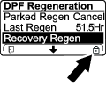
Preparing to Perform a Parked or Recovery Regeneration
-
Ensure that the machine has fuel in the tank for the type of regeneration you are performing:
-
Parked Regeneration: Ensure that you have 1/4 tank of fuel before performing the parked regeneration.
-
Recovery Regeneration: Ensure that you have 1/2 tank of fuel before performing the recovery regeneration.
-
-
Move the machine outside to an area away from combustible materials.
-
Park the machine on a level surface.
-
Ensure that the traction control or motion-control levers are in the NEUTRAL position.
-
If applicable, shut off the PTO, and lower the cutting units or accessories.
-
Engage the parking brake.
-
Set the throttle to the low IDLE position.
Performing a Parked or Recovery Regeneration
Caution
The exhaust temperature is hot (approximately 600°C (1,112°F) during DPF regeneration. Hot exhaust gas can harm you or other people.
-
Never operate the engine in an enclosed area.
-
Make sure that there are no flammable materials around the exhaust system.
-
Never touch a hot exhaust system component.
-
Never stand near or around the exhaust pipe of the machine.
Important: The computer of the machine cancels DPF regeneration if you increase the engine speed from low idle or release the parking brake.
-
Access the DPF Regeneration menu, press the center button to scroll down to either the PARKED REGEN START option or the RECOVERY REGEN START option (Figure 56), and press the right button to select the start the regeneration (Figure 56).


-
At the VERIFY FUEL LEVEL screen, verify that you have 1/4 tank of fuel if you are performing the parked regeneration or 1/2 tank of fuel if you are performing the recovery regeneration, and press the right button to continue (Figure 57).
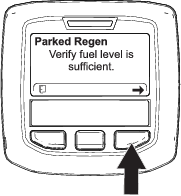

-
At the DPF checklist screen, verify that the parking brake is engaged and that the engine speed is set to low idle (Figure 58).
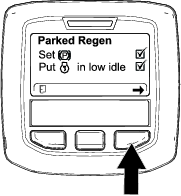
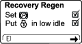
-
At the INITIATE DPF REGEN screen, press the right button to continue (Figure 59).
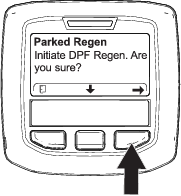

-
The InfoCenter displays the INITIATING DPF REGEN message (Figure 60).


-
The InfoCenter displays the time to complete message (Figure 61).

-
The engine computer checks the engine state and fault information. The InfoCenter may display the following messages found in the table that follows:
Note: If you attempt to do a forced parked regeneration before 50 hours of the last sucessful regeneration this message will appear.If the machine is requesting a regeneration and this message appears contact your authorized Toro distributor for service.
Check Message and Corrective Action Table

Corrective Action: Exit the regeneration menu and run the machine until the time since last regeneration is greater than 50 hours; refer to Time Since Last Regeneration. 

Corrective Action: Troubleshoot the engine fault and retry DPF regeneration. 

Corrective Action: Start and run the engine. 

Corrective Action: Run the engine to warm the coolant temperature to 60°C (140°F). 

Corrective Action: Change the engine speed to low idle. 

Corrective Action: Troubleshoot the engine computer condition and retry DPF regeneration. -
The InfoCenter displays the home screen and the regeneration acknowledge icon (Figure 62) appears in the lower right corner of the screen as the regeneration processes.
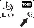
Note: While the DPF regeneration runs, the InfoCenter displays the high exhaust-temperature icon
. -
When the engine computer completes a parked or recovery regeneration, the InfoCenter displays ADVISORY #183 (Figure 63). Press the left button to exit to the home screen.
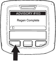
Note: If the regeneration fails to complete, the InfoCenter displays Advisory #184 (Figure 63). Press the left button to exit to the home screen.
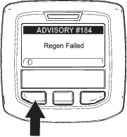
Operating Tips
Changing Mowing Patterns
Change mowing patterns often to minimize a poor after-cut appearance from repeatedly mowing in the same direction. This is the most effective way to prevent washboarding.
Resolving After-Cut Appearance
Refer to the After-cut Appearance Troubleshooting Guide available at www.Toro.com.
Using Proper Mowing Techniques
-
To achieve the professional straight-line cut and striping that is desirable for some applications, find a tree or other object in the distance and drive straight toward it.
-
Bolt-in mulching baffles are available for the cutting units. The mulching baffles perform well when you maintain turf on a regular schedule to avoid removing more than 25 mm (1 inch) of growth per cutting. When you cut too much growth with the mulching baffles installed, the after-cut appearance may deteriorate and the observed power to cut the turf increases. The mulching baffles also perform well for shredding leaves in the fall.
Selecting the Proper Height-of-Cut Setting to Suit Conditions
Remove no more than approximately 25 mm (1 inch), or 1/3 of the grass blade when cutting. In exceptionally lush and dense grass, you may need to raise your height-of-cut setting.
Mowing with Sharp Blades
A sharp blade cuts cleanly and without tearing or shredding the grass blades like a dull blade. Tearing and shredding causes the grass to turn brown at the edges, which impairs growth and increases susceptibility to diseases. Ensure that the blade is in good condition and that there is a full sail; refer to Servicing the Blade Plane.
Checking the Condition of the Cutting Unit
Ensure that the cutting chambers are in good condition. Straighten any bends in the chamber components to ensure correct blade tip/chamber clearance. Ensure all rollers and pivoting joints do not have play in them to prevent turf damage or poor after cut appearance.
Maintaining the Machine after Mowing
After mowing, thoroughly wash the machine with a garden hose with no nozzle to avoid contamination and damage to the seals and bearings caused by excessive water pressure. Ensure that the radiator and oil cooler are kept free of dirt or grass clippings. After cleaning, inspect the machine for possible hydraulic-fluid leaks, damage, or wear to the hydraulic and mechanical components, and check the cutting-unit blades for sharpness.
After Operation
General Safety
-
Shut off the engine, remove the key, and wait for all movement to stop before you leave the operator’s position. Allow the machine to cool before adjusting, servicing, cleaning, or storing it.
-
To help prevent fires, ensure that the cutting units, drives, mufflers, cooling screens, and engine compartment are free from grass and debris buildup. Clean up oil or fuel spills.
-
If the cutting units are in the transport position, use the positive mechanical lock (if available) before you leave the machine unattended.
-
Allow the engine to cool before storing the machine in any enclosure.
-
Remove the key and shut off the fuel (if equipped) before storing or hauling the machine.
-
Never store the machine or fuel container where there is an open flame, spark, or pilot light, such as on a water heater or on other appliances.
-
Maintain and clean the seat belt(s) as necessary
Identifying the Tie-Down Points
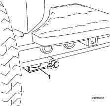
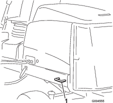
Hauling the Machine
-
Remove the key and shut off the fuel (if equipped) before storing or transporting the machine.
-
Use care when loading or unloading the machine into a trailer or a truck.
-
Use full-width ramps for loading the machine into a trailer or a truck.
-
Tie the machine down securely.
Pushing or Towing the Machine
In an emergency, you can move the machine forward by actuating the bypass valve in the variable-displacement hydraulic pump and pushing or towing the machine.
Important: Do not push or tow the machine faster than 3 to 4.8 km/h (2 to 3 mph). If you push or tow at a faster speed, internal transmission damage may occur.The bypass valves must be open and the brake released whenever you push or tow the machine.
-
Unlatch the seat base and tilt the seat open.
-
Locate the bypass valve under the seat and on the top of the hydrostat (Figure 67).
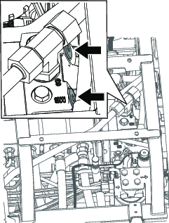
-
Loosen the valves with 3 turns to allow the oil to bypass internally.
Note: Because the fluid is bypassed, the machine can be moved slowly without damaging the transmission.
-
Locate the brake release manifold near the front right tire and behind the hydraulic tank (Figure 68).
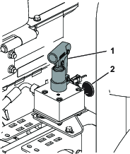
-
Insert the long end of a ratchet or similar object, hold the black knob in on the manifold, and pump the manifold 3 times. As soon as there is substantial resistance when pumping the brake is released.
Important: Do not pump the manifold after it does not pump easily. Damage could occur if the manifold is pumped too much.
Note: Once the pressure is built up in the manifold, the brake will be released for approximately 60 minutes. If needed after 60 minutes, release the brake again by pumping the manifold.
-
Push or tow the machine.
-
Set the brake by pulling the black knob out or starting the engine.
Note: The brake automatically resets when you start the engine and you do not need to pull the black knob out.
-
Close the bypass valves. Torque the valves to 11 N∙m (5 to 8 ft-lb).
Important: Ensure that the bypass valves are closed before you start operating the machine. Running the engine with an open bypass valve causes the transmission to overheat.
Maintenance
Note: Determine the left and right sides of the machine from the normal operating position.
Maintenance Safety
-
Before you leave the operator’s position, do the following:
-
Park the machine on a level surface.
-
Disengage the power takeoff and lower the attachments.
-
Engage the parking brake.
-
Shut off the engine and remove the key.
-
Wait for all movement to stop.
-
-
Wear appropriate clothing, including eye-protection; long pants and substantial, slip-resistant footwear. Keep hands, feet, clothing, jewelry, and long hair away from moving parts.
-
If you leave the key in the switch, someone could accidently start the engine and seriously injure you or other bystanders. Remove the key from the switch before you perform any maintenance.
-
Allow machine components to cool before performing maintenance.
-
If the cutting units are in the transport position, use the positive mechanical lock (if equipped) before you leave the machine unattended.
-
If possible, do not perform maintenance while the engine is running. Keep away from moving parts.
-
Operate the engine only in well-ventilated areas. Exhaust gases contain carbon monoxide, which is lethal if inhaled.
-
Support the machine with jack stands whenever you work under the machine.
-
Carefully release pressure from components with stored energy.
-
Keep all parts of the machine in good working condition and all hardware tightened, especially blade-attachment hardware.
-
Replace all worn or damaged decals.
-
To ensure safe, optimal performance of the machine, use only genuine Toro replacement parts. Replacement parts made by other manufacturers could be dangerous, and such use could void the product warranty.
Recommended Maintenance Schedule(s)
| Maintenance Service Interval | Maintenance Procedure |
|---|---|
| After the first hour |
|
| After the first 10 hours |
|
| Before each use or daily |
|
| Every 50 hours |
|
| Every 100 hours |
|
| Every 200 hours |
|
| Every 250 hours |
|
| Every 400 hours |
|
| Every 800 hours |
|
| Every 1,000 hours |
|
| Every 2,000 hours |
|
| Every 3,000 hours |
|
| Before storage |
|
| Every 2 years |
|
Important: If you are performing maintenance on the machine and run the engine with an engine exhaust-extraction duct, set the inhibit regen setting to ON; refer to Setting the Inhibit Regen.
Pre-Maintenance Procedures
Preparing for Maintenance
| Maintenance Service Interval | Maintenance Procedure |
|---|---|
| Before each use or daily |
|
-
Park the machine on a level surface.
-
Engage the parking brake.
-
Disengage the PTO.
-
Move the lower mow/raise control to the MOW position.
-
Shut off the engine, and remove the key.
-
Wait for all parts to stop moving.
-
Allow the engine to cool.
Tilting the Seat
Lowering the Seat
-
Rotate the seat slightly, and lift the front prop rod out of the dent of the seat-support slot.
-
Carefully lower the seat until it latches securely.
Jacking Point Locations
Note: Support the machine with jack stands whenever you work under the machine.
Use the following as machine-lift points:
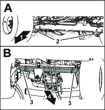
-
Front—the jack brackets of the front-axle tube (Figure 70).
-
Rear—the rear-axle tube.
Lubrication
Greasing the Bearings and Bushings
| Maintenance Service Interval | Maintenance Procedure |
|---|---|
| Every 50 hours |
|
If you operate the machine under normal conditions, use No. 2 lithium grease to lubricate all bearings and bushings at the specified maintenance interval. Lubricate bearings and bushings immediately after every washing, regardless of the interval listed.
The grease fitting locations and quantities are as follows:
-
Pump driveshaft U-joint (3)—Figure 71
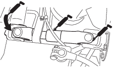
-
Cutting unit lift-arm cylinders (2 each)—Figure 72
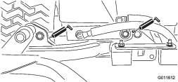
-
Lift-arm pivots (1 each)—Figure 72
-
Cutting unit carrier-frame pivot (1 each)—Figure 73
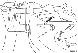
-
Lift-arm pivot shaft (1 each)—Figure 74

-
Axle-steering pivot (1)—Figure 75

-
Steering-cylinder ball joints (2) and rear axle (1)—Figure 76
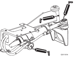
-
Cutting unit spindle-shaft bearings (2 per cutting unit)—Figure 77
Note: You can use either fitting, whichever is more accessible. Pump grease into the fitting until a small amount appears at bottom of the spindle housing (under the cutting unit).
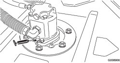
-
Rear-roller bearings (2 per cutting unit)—Figure 78
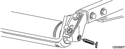
Note: Ensure that the grease groove in each roller mount aligns with the grease hole in each end of the roller shaft. To help align the groove and hole, there is also an alignment mark on 1 end of the roller shaft.
Engine Maintenance
Engine Safety
-
Shut off the engine and remove the key before checking the oil or adding oil to the crankcase.
-
Do not change the governor speed or overspeed the engine.
Servicing the Air Cleaner
| Maintenance Service Interval | Maintenance Procedure |
|---|---|
| Every 400 hours |
|
Check the whole intake system for leaks, damage, or loose hose clamps. Do not use a damaged air filter.
Service the air-cleaner filter only when the service indicator requires it. Changing the air filter before it is necessary only increases the chance of dirt entering the engine when the filter is removed.
Important: Make sure that the cover is seated correctly, seals with the air-cleaner body, and the rubber outlet valve is in a downward position—between the 5 o’clock and 7 o’clock positions when viewed from the end.
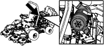
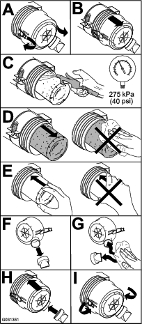
Servicing the Engine Oil
Oil Specification
Toro Premium Engine Oil is available from your authorized Toro distributor in either 15W-40 or 10W-30 viscosity grades.
Use high-quality, low-ash engine oil that meets or exceeds the following specifications:
-
API service category CJ-4 or higher
-
ACEA service category E6
-
JASO service category DH-2
Important: Using engine oil other than API CJ-4 or higher, ACEA E6, or JASO DH-2 may cause the diesel particulate filter to plug or cause engine damage.
Use the following engine oil viscosity grade:
-
Preferred oil: SAE 15W-40 (above 0°F)
-
Alternate oil: SAE 10W-30 or 5W-30 (all temperatures)
Checking the Engine-Oil Level
| Maintenance Service Interval | Maintenance Procedure |
|---|---|
| Before each use or daily |
|
The engine is shipped with oil in the crankcase; however, the oil level must be checked before and after the engine is first started.
Important: Check the engine oil daily. If the engine-oil level is above the Full mark on the dipstick, the engine oil may be diluted with fuel;If the engine oil level is above the Full mark, change the engine oil.
The best time to check the engine oil is when the engine is cool before it has been started for the day. If it has already been run, allow the oil to drain back down to the sump for at least 10 minutes before checking. If the oil level is at or below the Add mark on the dipstick, add oil to bring the oil level to the Full mark. Do not overfill the engine with oil.
Important: Keep the engine oil level between the upper and lower limits on the dipstick; the engine may fail if you run it with too much or too little oil.
-
Park the machine on a level surface.
-
Check the engine-oil level (Figure 80).
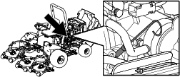
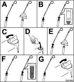
Note: When using different oil, drain all old oil from the crankcase before adding new oil.
Crankcase Oil Capacity
Approximately 5.2 L (5.5 US qt) with the filter.
Changing the Engine Oil and Filter
| Maintenance Service Interval | Maintenance Procedure |
|---|---|
| Every 250 hours |
|
-
Start the engine and let it run 5 minutes to allow the oil to warm up.
-
With the machine parked on a level surface, shut off the engine, remove the key, and wait for all moving parts to stop before leaving the operating position.
-
Replace the engine oil and filter (Figure 81).
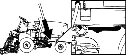
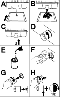
-
Add oil to the crankcase.
Fuel System Maintenance
Fuel Maintenance
This Operator’s Manual contains more detailed fuel and fuel system maintenance information than the Yanmar® engine Owner’s Manual, which is a general-purpose reference relating to fuel and fuel maintenance.
Ensure that you understand that the fuel system maintenance, fuel storage, and fuel quality require your attention to avoid downtime and extensive engine repairs.
The fuel system has extremely tight tolerances due to the emissions and control requirements. Diesel fuel quality and cleanliness is more important for the longevity of today’s high-pressure common rail (HPCR) fuel-injection system used on diesel engines.
Important: Water or air in the fuel system will damage your engine! Do not assume that new fuel is clean. Ensure that your fuel is from a quality supplier, store your fuel correctly, and use your fuel supply within 180 days.
Important: If you do not follow the procedures for fuel filter replacement, fuel system maintenance, and fuel storage, the engine fuel system could fail prematurely. Perform all fuel system maintenance at the specified intervals or whenever the fuel is contaminated or its quality is poor.
Storing Fuel
Appropriate fuel storage is critical for your engine. Proper maintenance of fuel storage tanks is often overlooked and leads to the contamination of fuel delivered to the machine.
-
Acquire only enough fuel that you will consume within 180 days. Do not use fuel that has been stored for more than 180 days. This helps eliminate water and other contaminates in the fuel.
-
If you do not remove the water from the storage tank or machine fuel tank, it can lead to rust or contamination in the storage tank and fuel system components. Tank sludge developed by mold, bacteria, or fungus restricts flow and clogs the filter and fuel injectors.
-
Inspect your fuel storage tank and machine fuel tank regularly to monitor the fuel quality in the tank.
-
Ensure that your fuel comes from a quality supplier.
-
If you find water or contaminants in your storage tank or machine fuel tank, work with your fuel provider to correct the problem and perform all fuel system maintenance.
-
Do not store diesel fuel in tanks or canisters made with zinc-plated components.
Servicing the Fuel-Water Separator
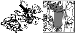
Draining Water from the Fuel/Water Separator
| Maintenance Service Interval | Maintenance Procedure |
|---|---|
| Before each use or daily |
|
-
Drain water from the fuel/water separator as shown in Figure 83.
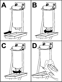
-
Prime the filter and the lines to the high pressure pump; refer to Priming the Fuel System.
Replacing the Fuel/Water Separator Filter
| Maintenance Service Interval | Maintenance Procedure |
|---|---|
| Every 400 hours |
|
-
Replace the filter as shown in Figure 84.
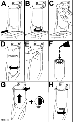
-
Prime the filter and the lines to the high pressure pump; refer to Priming the Fuel System.
Servicing the Fuel Filter
| Maintenance Service Interval | Maintenance Procedure |
|---|---|
| Every 400 hours |
|
-
Clean the area around the fuel-filter head (Figure 85).
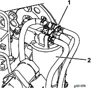
-
Remove the filter and clean the filter head mounting surface (Figure 85).
Note: Use a clean cloth to clean the filter head.
-
Lubricate the filter gasket with clean lubricating engine oil; refer to the engine owner's manual for additional information.
-
Install the dry filter canister by hand until the gasket contacts the filter head, then rotate it an additional 1/2 turn.
-
Prime the filter and the lines to the high pressure pump; refer to Priming the Fuel System.
-
Start the engine and inspect for leaks around the filter head again.
Draining the Fuel Tank
| Maintenance Service Interval | Maintenance Procedure |
|---|---|
| Every 800 hours |
|
| Before storage |
|
In addition to the listed service interval, drain and clean the tank if the fuel system becomes contaminated or if you are storing the machine for an extended period. Use clean fuel to flush out the tank.
Prime the filter and the lines to the high pressure pump; refer to Priming the Fuel System.
Inspecting the Fuel Lines and Connections
| Maintenance Service Interval | Maintenance Procedure |
|---|---|
| Every 400 hours |
|
Inspect the fuel lines for deterioration, damage, or loose connections.
Replace any deteriorated clamps or hoses.
Note: Prime the fuel system if you replace any fuel lines; refer to Priming the Fuel System.
Servicing the Diesel-Oxidation Catalyst (DOC) and the Soot Filter
| Maintenance Service Interval | Maintenance Procedure |
|---|---|
| Every 3,000 hours |
|
If engine faults , , or in the InfoCenter (Figure 86) display in the InfoCenter, clean the soot filter using the steps that follow:
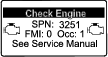
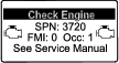
-
Refer to the Engine section in the Service Manual for information on disassembling and assembling the diesel-oxidation catalyst and the soot filter of the DPF.
-
Refer to your authorized Toro distributor for diesel-oxidation catalyst and the soot filter replacement parts or service.
-
Contact your authorized Toro distributor to have them reset the engine ECU after you install a clean DPF.
Priming the Fuel System
Prime the fuel system after the following scenarios:
-
Replacing the fuel filter.
-
Draining the water separator after each use or daily.
-
Running out of fuel.
-
Replacing a fuel hose or open the fuel system for any reason.
To prime the fuel system, perform the following steps:
Important: Do not use the engine-starter motor to crank the engine for fuel-system priming.
-
Ensure that fuel is in the fuel tank.
-
Perform the following steps to prime the filter and the lines to the high-pressure pump to prevent wear or damage to the pump:
-
Cycle the key to the ON position for 15 to 20 seconds.
-
Cycle the key to the OFF position for 30 to 40 seconds.
Note: This allows the ECU to power down.
-
Cycle the key to the ON position for 15 to 20 seconds.
-
Inspect for leaks around the filter and hoses.
-
Start the engine and inspect for leaks.
-
Electrical System Maintenance
Electrical System Safety
-
Disconnect the battery before repairing the machine. Disconnect the negative terminal first and the positive last. Connect the positive terminal first and the negative last.
-
Charge the battery in an open, well-ventilated area, away from sparks and flames. Unplug the charger before connecting or disconnecting the battery. Wear protective clothing and use insulated tools.
Servicing the Battery
| Maintenance Service Interval | Maintenance Procedure |
|---|---|
| Every 50 hours |
|
Perform the following tasks to service the battery:
-
Check the battery condition
-
Clean the battery (if necessary)
Note: To clean the battery, wash the entire case with a solution of baking soda and water. Rinse it with clear water.
-
Check the battery-cable connections and coat the battery posts and cable connectors with Grafo 112X (skin-over) grease or petroleum jelly to prevent corrosion.
Important: Before welding on the machine, disconnect the negative cable from the battery to prevent damage to the electrical system. Also, you must disconnect the engine, InfoCenter, and machine controllers before welding on the machine.
Replacing the Fuses
The fuse block (Figure 88) is located under the seat. Refer to Figure 90 for a description of each fuse.
-
Unlatch the seat base, tilt the seat base open, and support it with the prop rods.
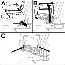
-
Replace the open fuse with the same fuse type and amperage rating.
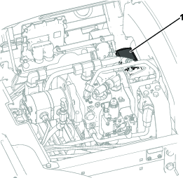
-
Rotate the seat and seat base closed and latch the base.
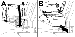
Charging the Battery
Warning
Charging the battery produces gasses that can explode.
Do not smoke near the battery, and keep sparks and flames away from the battery.
Important: Keep the battery fully charged. This is especially important to prevent battery damage when the temperature is below 0°C (32°F).
-
Clean the exterior of the battery case and the battery posts.
Note: Connect the leads of the battery charger to battery posts before connecting the charger to the electrical source.
-
Look at the battery and identify the positive and negative battery posts.
-
Connect the positive lead of the battery charger to the positive battery post (Figure 91).
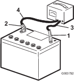
-
Connect the negative lead of the battery charger to the negative-battery post (Figure 91).
-
Connect the battery charger to the electrical source, and charge the battery.
Important: Do not overcharge the battery.
-
When the battery is fully charged, unplug the charger from the electrical source, then disconnect the charger leads from the battery posts (Figure 91).
Drive System Maintenance
Adjusting the Rear Wheel Toe-in
| Maintenance Service Interval | Maintenance Procedure |
|---|---|
| Every 800 hours |
|
-
Rotate the steering wheel so that the rear wheels are straight ahead.
-
Loosen the jam nut on each end of the tie rod (Figure 92).
Note: The end of the tie rod with the external groove is a left-hand thread.
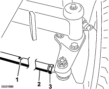
-
Using the wrench slot, rotate the tie rod.
-
Measure the distance at the front and rear of the rear wheels at axle height.
Note: The distance at the front of the rear wheels should be less than 6 mm (1/4 inch) of the distance measured at the rear of the wheels.
-
Repeat procedure as required.
Cooling System Maintenance
Cooling System Safety
-
Swallowing engine coolant can cause poisoning; keep out of reach from children and pets.
-
Discharge of hot, pressurized coolant or touching a hot radiator and surrounding parts can cause severe burns.
-
Always allow the engine to cool at least 15 minutes before removing the radiator cap.
-
Use a rag when opening the radiator cap, and open the cap slowly to allow steam to escape.
-
-
Do not operate the machine without the covers in place.
-
Keep your fingers, hands, and clothing clear of the rotating fan and drive belt.
Coolant Specification
The coolant reservoir is filled at the factory with a 50/50 solution of water and ethylene glycol base extended-life coolant.
Important: Use only commercially available coolants that meet the specifications listed in the Extended Life Coolant Standards Table.Do not use conventional (green) inorganic-acid technology (IAT) coolant in your machine. Do not mix conventional coolant with extended-life coolant.
|
Ethylene-Glycol Coolant Type |
Corrosion Inhibitor Type |
|
Extended-life antifreeze |
Organic-acid technology (OAT) |
|
Important: Do not rely on the color of the coolant to identify the difference between conventional (green) inorganic-acid technology (IAT) coolant and extended-life coolant.Coolant manufacturers may dye extended-life coolant in one of the following colors: red, pink, orange, yellow, blue, teal, violet, and green. Use coolant that meets the specifications in the Extended Life Coolant Standards Table. |
|
|
ATSM International |
SAE International |
|
D3306 and D4985 |
J1034, J814, and 1941 |
Important: Coolant concentration should be a 50/50 mixture of coolant to water.
-
Preferred: When mixing coolant from a concentrate, mix it with distilled water.
-
Preferred option: If distilled water is not available, use a pre-mix coolant instead of a concentrate.
-
Minimum requirement: If distilled water and pre-mix coolant are not available, mix concentrated coolant with clean drinkable water.
Checking the Cooling System
| Maintenance Service Interval | Maintenance Procedure |
|---|---|
| Before each use or daily |
|
The cooling system is filled with a 50/50 solution of water and permanent ethylene glycol antifreeze. The capacity of the cooling system is 9.5 L (10 US qt).
-
Check the level of coolant in the expansion tank (Figure 93).
Note: The coolant level should be between the marks on the side of the tank.
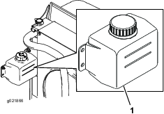
-
If the coolant level is low, remove the expansion-tank cap and replenish the system. Do not overfill.
-
Install the expansion-tank cap.
Cleaning the Cooling System
| Maintenance Service Interval | Maintenance Procedure |
|---|---|
| Before each use or daily |
|
| Every 100 hours |
|
| Every 2 years |
|
Remove debris from the screen and radiator/oil cooler daily (clean more frequently in dirty conditions).
-
Turn the key in the ignition switch to the OFF position and remove the key.
-
Thoroughly clean all debris out of the engine area.
-
Unlatch the clamp and pivot open the rear screen (Figure 94).
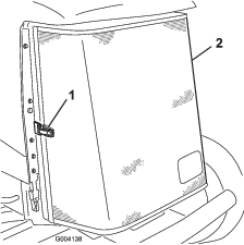
-
Thoroughly clean both sides of the radiator and oil cooler (Figure 95) with compressed air.
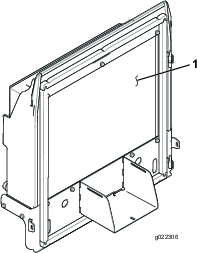
-
Close the screen and secure the latch.
Belt Maintenance
Servicing the Alternator Belt
| Maintenance Service Interval | Maintenance Procedure |
|---|---|
| After the first 10 hours |
|
| Every 100 hours |
|
Note: For proper belt tension, allow 10 mm (3/8 inch) deflection when a force of 44 N (10 lb) is applied on the belt midway between the pulleys.
-
If the deflection is not 10 mm (3/8 inch), loosen the alternator mounting bolts (Figure 96).
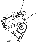
-
Increase or decrease the alternator-belt tension and tighten the bolts.
-
Check the deflection of the belt again to ensure that the tension is correct.
Hydraulic System Maintenance
Hydraulic System Safety
-
Seek immediate medical attention if fluid is injected into skin. Injected fluid must be surgically removed within a few hours by a doctor.
-
Ensure that all hydraulic-fluid hoses and lines are in good condition and all hydraulic connections and fittings are tight before applying pressure to the hydraulic system.
-
Keep your body and hands away from pinhole leaks or nozzles that eject high-pressure hydraulic fluid.
-
Use cardboard or paper to find hydraulic leaks.
-
Safely relieve all pressure in the hydraulic system before performing any work on the hydraulic system.
Hydraulic Fluid Specifications
The reservoir is filled at the factory with high-quality hydraulic fluid. Check the level of the hydraulic fluid before you first start the engine and daily thereafter; refer to Checking the Hydraulic-Fluid Level.
Recommended hydraulic fluid: Toro PX Extended Life Hydraulic Fluid; available in 19 L (5 US gallon) pails or 208 L (55 US gallon) drums.
Note: A machine using the recommended replacement fluid requires less frequent fluid and filter changes.
Alternative hydraulic fluids: If Toro PX Extended Life Hydraulic Fluid is not available, you may use another conventional, petroleum-based hydraulic fluid having specifications that fall within the listed range for all the following material properties and that it meets industry standards. Do not use synthetic fluid. Consult with your lubricant distributor to identify a satisfactory product.
Note: Toro does not assume responsibility for damage caused by improper substitutions, so use products only from reputable manufacturers who will stand behind their recommendation.
| Material Properties: | ||
| Viscosity, ASTM D445 | cSt @ 40°C (104°F) 44 to 48 | |
| Viscosity Index ASTM D2270 | 140 or higher | |
| Pour Point, ASTM D97 | -37°C to -45°C (-34°F to -49°F) | |
| Industry Specifications: | Eaton Vickers 694 (I-286-S, M-2950-S/35VQ25 or M-2952-S) | |
Note: Many hydraulic fluids are almost colorless, making it difficult to spot leaks. A red dye additive for the hydraulic fluid is available in 20 ml (0.67 fl oz) bottles. A bottle is sufficient for 15 to 22 L (4 to 6 US gallons) of hydraulic fluid. Order Part No. 44-2500 from your authorized Toro distributor.
Important: Toro Premium Synthetic Biodegradable Hydraulic Fluid is the only synthetic biodegradable fluid approved by Toro. This fluid is compatible with the elastomers used in Toro hydraulic systems and is suitable for a wide-range of temperature conditions. This fluid is compatible with conventional mineral oils, but for maximum biodegradability and performance, the hydraulic system should be thoroughly flushed of conventional fluid. The oil is available in 19 L (5 US gallon) pails or 208 L (55 US gallon) drums from your authorized Toro distributor.
Checking the Hydraulic-Fluid Level
| Maintenance Service Interval | Maintenance Procedure |
|---|---|
| Before each use or daily |
|
| Every 200 hours |
|
-
Position the machine on a level surface, lower the cutting decks, and turn the key in the switch to the OFF position.
-
Check the hydraulic-fluid level (Figure 97).
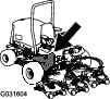
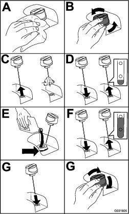
Changing the Hydraulic Fluid
| Maintenance Service Interval | Maintenance Procedure |
|---|---|
| Every 800 hours |
|
| Every 2,000 hours |
|
| Every 2 years |
|
Hydraulic Fluid Capacity: 56.7 L (15 US gallons)
If fluid becomes contaminated, contact your Toro Distributor because the system must be flushed. Contaminated fluid looks milky or black when compared to clean oil.
-
Turn the key in the switch to the OFF position and raise the hood.
-
Place a large drain pan under the fitting secured to the bottom of the hydraulic-fluid reservoir (Figure 98).
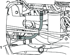
-
Disconnect the hose from the bottom of the fitting and let the hydraulic fluid flow into the drain pan.
-
Install the hose when hydraulic fluid stops draining.
-
Fill the reservoir with hydraulic fluid (Figure 97).
Important: Use only hydraulic fluids specified. Other fluids could cause system damage.
-
Install the reservoir cap.
-
Turn the key in the switch to the ON position, start the engine, use all of the hydraulic controls to distribute hydraulic fluid throughout the system, and check for leaks.
-
Turn the key in the switch to the OFF position.
-
Check the level of the hydraulic fluid and add enough to raise level to the Full mark on the dipstick.
Important: Do not overfill.
Replacing the Hydraulic Filters
| Maintenance Service Interval | Maintenance Procedure |
|---|---|
| Every 800 hours |
|
| Every 1,000 hours |
|
The hydraulic system is equipped with a service-interval indicator (Figure 99). With the engine running, view the indicator, it should be in the green zone. When the indicator is in the red zone, change the hydraulic filters.
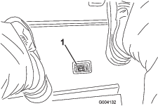
Important: Use of any other filters may void the warranty on some components.
-
Position the machine on a level surface, lower the cutting decks, turn the key in the switch to the OFF position, engage the parking brake, and remove the key.
-
Replace both of the hydraulic filters (Figure 100).

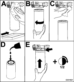
-
Turn the key in the switch to the ON position, start the engine, and let it run for about 2 minutes to purge air from the system.
-
Turn the key in the switch to the OFF position and check for leaks.
Checking the Hydraulic Lines and Hoses
| Maintenance Service Interval | Maintenance Procedure |
|---|---|
| Before each use or daily |
|
| Every 2 years |
|
Make all necessary repairs before operating.
Warning
Hydraulic fluid escaping under pressure can penetrate skin and cause injury.
-
Seek immediate medical help if fluid is injected into skin.
-
Make sure that all hydraulic-fluid hoses and lines are in good condition and all hydraulic connections and fittings are tight before applying pressure to the hydraulic system.
-
Keep your body and hands away from pinhole leaks or nozzles that eject high-pressure hydraulic fluid.
-
Use cardboard or paper to find hydraulic leaks.
-
Safely relieve all pressure in the hydraulic system before performing any work on the hydraulic system.
Testing the Hydraulic-System Pressure
Use the hydraulic system test ports to test the pressure in the hydraulic circuits. Contact your authorized Toro distributor for assistance.
Hydraulic Valve Solenoid Functions
Use the list below to identify and describe the different functions of the solenoids in the hydraulic manifold. Each solenoid must be energized to allow function to occur.
| Solenoid | Function |
|---|---|
| PRV2 | Front mower circuit |
| PRV1 | Rear mower circuit |
| PRV | Lift/lower cutting decks |
| S1 | Lower cutting decks |
| S2 | Lower cutting decks |
Cutting Unit Maintenance
Separating the Cutting Unit from the Traction Unit
-
Position the machine on a level surface, lower the cutting units to the floor, turn the key in the switch to the OFF position, and engage the parking brake.
-
Disconnect and remove the hydraulic motor from the cutting unit (Figure 101). Cover the top of the spindle to prevent contamination.
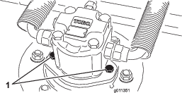
-
Remove the lynch pin securing the deck-carrier frame to the lift-arm pivot pin (Figure 102).
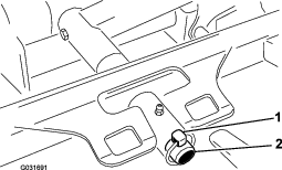
-
Roll the cutting unit away from the traction unit.
Mounting the Cutting Units to the Traction Unit
-
Position the machine on a level surface and turn the key in the switch to the OFF position.
-
Move the cutting unit into position in front of the traction unit.
-
Slide the deck-carrier frame onto the lift-arm pivot pin and secure it with the lynch pin (Figure 102).
-
Install the hydraulic motor to the deck (Figure 101). Make sure that the O-ring is in position and not damaged.
-
Grease the spindle.
Servicing the Front Roller
Inspect the front roller for wear, excess wobble, or binding. Service or replace the roller or components if any of these conditions exist.
Disassembling the Front Roller
-
Remove the roller-mounting bolt (Figure 103).
-
Insert a punch through the end of the roller housing and drive the opposite bearing out by alternating taps to the opposite side of inner bearing race. There should be a 1.5 mm (0.060 inch) lip of inner race exposed.

-
Push the second bearing out in press.
-
Inspect the roller housing, bearings, and bearing spacer for damage (Figure 103). Replace any damaged components and assemble them.
Assembling the Front Roller
-
Press the first bearing into the roller housing (Figure 103). Press on the outer race only or equally on the inner and outer race.
-
Insert the spacer (Figure 103).
-
Press the second bearing into the roller housing (Figure 103). Pressing equally on the inner and outer race until the inner race contacts the spacer.
-
Install the roller assembly into the cutting-unit frame.
-
Verify that there is no more than a 1.5 mm (0.060 inch) gap between roller assembly and the roller mount brackets of the cutting-unit frame. If there is a gap over 1.5 mm (0.060 inch), install enough 5/8-inch diameter washers to take up the slop.
Important: Securing the roller assembly with a gap larger than 1.5 mm (0.060 inch) creates a side load on the bearing and can lead to premature bearing failure
-
Torque the mounting bolt to 108 N∙m (80 ft-lb).
Blade Maintenance
Blade Safety
-
Inspect the blade periodically for wear or damage.
-
Use care when checking the blades. Wrap the blades or wear gloves, and use caution when servicing the blades. Only replace or sharpen the blades; never straighten or weld them.
-
On multi-bladed machines, take care as rotating one blade can cause other blades to rotate.
Servicing the Blade Plane
The rotary deck comes from the factory preset at 5 cm (2 inches) height of cut and blade rake of 7.9 mm (0.310 inch). The left and right heights are also preset to within ± 0.7 mm (0.030 inch) of the other.
The cutting deck is designed to withstand blade impacts without deformation of the chamber. If a solid object is struck, inspect the blade for damage and the blade plane for accuracy.
Inspecting the Blade Plane
-
Remove the hydraulic motor from the cutting deck and remove the cutting deck from the tractor.
-
Use a hoist (or minimum of 2 people) and place the cutting deck on a flat table.
-
Mark 1 end of the blade with a paint pen or marker. Use this end of the blade to check all heights.
-
Position the cutting edge of the marked end of the blade at 12 o’clock (straight ahead in the direction of mowing) (Figure 104) and measure height from table to cutting edge of blade.
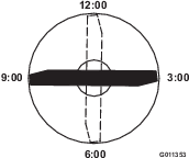
-
Rotate the marked end of the blade to the 3 and 9 o’clock positions (Figure 104) and measure the heights.
-
Compare the 12 o’clock measured height to the height-of-cut setting. It should be within 0.7 mm (0.030 inch). The 3 and 9 o’clock heights should be 1.6 to 6.0 mm (0.06 to 0.24 inch) higher than the 12 o’clock setting and within 1.6 to 6.0 mm (0.06 to 0.24 inch) of each other.
Note: If any of these measurements are not within specification, proceed to Adjusting the Blade Plane.
Adjusting the Blade Plane
Start with the front adjustment (change 1 bracket at a time).
-
Remove the height-of-cut bracket (front, left, or right) from the deck frame (Figure 105).
-
Adjust 1.5 mm (0.060 inch) shims and/or 0.7 mm (0.030 inch) shim between the deck frame and bracket to achieve the desired height setting (Figure 105).
-
Install the height-of-cut bracket to the deck frame with the remaining shims assembled below the height-of-cut bracket.
-
Secure the socket-head bolt/spacer and flange nut.
Note: Socket-head bolt/spacer are held together with thread-locking adhesive to prevent the spacer from falling inside the deck frame.
-
Verify the 12 o’clock height and adjust if needed.
-
Determine if only 1 or both (right and left) height-of-cut brackets need to be adjusted. If the 3 or 9 o’clock side is 1.6 to 6.0 mm (0.06 to 0.24 inch) higher than the new front height then no adjustment is needed for that side. Adjust the other side to within 1.6 to 6.0 mm (0.06 to 0.24 inch) of the correct side.
-
Adjust the right and/or left height-of-cut brackets by repeating steps 1 through 3.
-
Secure the carriage bolts and flange nuts.
-
Again, verify the 12, 3, and 9 o’clock heights.
Removing and Installing the Cutting-Unit Blade(s)
Replace the blade if it hits a solid object, is out of balance, or is bent. Always use genuine Toro replacement blades to ensure safety and optimum performance.
-
Park the machine on a level surface, raise the cutting unit to the transport position, engage the parking brake, shut off the engine, and remove the key.
Note: Block or lock the cutting unit to prevent it from accidentally falling.
-
Grasp the end of the blade using a rag or thickly-padded glove.
-
Remove the blade bolt, anti-scalp cup, and blade from the spindle shaft (Figure 106).

-
Install the blade, anti-scalp cup, and blade bolt and tighten the blade bolt to 115 to 149 N∙m (85 to 110 ft-lb).
Important: The curved part of the blade must be pointing toward the inside of the cutting unit to ensure proper cutting.
Note: 7After striking a foreign object, torque all spindle-pulley nuts to 115 to 149 N∙m (85 to 110 ft-lb).
Inspecting and Sharpening the Blade
-
Raise the cutting deck to the transport position, turn the key in the ignition switch to the OFF position, and engage the parking brake.
-
Block the cutting deck to prevent it from falling accidentally.
-
Examine the cutting ends of the blade carefully, especially where the flat and curved parts of the blade meet (Figure 107).
Note: Since sand and abrasive material can wear away the metal that connects the flat and curved parts of the blade, check the blade before using the machine.
-
If wear is noticed (Figure 107), replace the blade; refer to Removing and Installing the Cutting-Unit Blade(s).
Danger
If the blade is allowed to wear, a slot will form between the sail and flat part of the blade (Figure 107). Eventually a piece of the blade may break off and be thrown from under the housing, possibly resulting in serious injury to yourself or bystanders.
-
Inspect the blade periodically for wear or damage.
-
Always replace a worn or damaged blade.
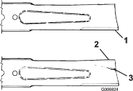
-
-
Inspect the cutting edges of all blades. Sharpen the cutting edges if they are dull or nicked. Sharpen only the top of the cutting edge and maintain the original cutting angle to make sure that it is sharp (Figure 108).
-
If dull or nicked, sharpen only the top cutting edge while maintaining the original cutting angle (Figure 108).
Note: The blade will remain balanced if the same amount of metal is removed from both cutting edges.

-
To check the blade for being straight and parallel, lay the blade on a level surface and check its ends.
Note: Position the ends of the blade slightly lower than the center, and the cutting edge lower than the heel of the blade. This blade produces a good quality of cut and requires minimal power from the engine. By contrast a blade that is higher at the ends than the center, or if cutting edge is higher than the heel, the blade is bent or warped and must be replaced.
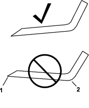
-
Install the blade, sail facing toward cutting deck, with the anti-scalp cup and blade bolt. Torque the blade bolt to 115 to 149 N∙m (85 to 110 ft-lb).
Storage
Storage Safety
-
Shut off the engine, remove the key, and wait for all movement to stop before you leave the operator’s position. Allow the machine to cool before adjusting, servicing, cleaning, or storing it.
-
Do not store the machine or fuel container where there is an open flame, spark, or pilot light, such as on a water heater or other appliance.
Preparing the Machine for Storage
Important: Do not use brackish or reclaimed water to clean the machine.
Preparing the Traction Unit
-
Thoroughly clean the traction unit, cutting units, and engine.
-
Check the tire pressure. Inflate all traction unit tires to 83 to 103 kPa (12 to 15 psi).
-
Check all fasteners for looseness and tighten them as necessary.
-
Grease all grease fittings and pivot points. Wipe up any excess lubricant.
-
Lightly sand and use touch-up paint on painted areas that are scratched, chipped, or rusted. Repair any dents in the metal body.
-
Service the battery and cables as follows:
-
Remove the battery terminals from the battery posts.
Note: Always disconnect the negative terminal first and the positive last. Always connect the positive terminal first and the negative last.
-
Clean the battery, terminals, and posts with a wire brush and baking soda solution.
-
Coat the cable terminals and battery posts with Grafo 112X skin-over grease (Part Number 505-47) or petroleum jelly to prevent corrosion.
-
Slowly recharge the battery every 60 days for 24 hours to prevent lead sulfation of the battery.
-
Preparing the Engine
-
Drain the engine oil from the oil pan and replace the drain plug.
-
Remove and discard the oil filter. Install a new oil filter.
-
Refill the oil pan with designated quantity of motor oil.
-
Turn the key in the switch to the ON position, start the engine, and run it at idle speed for approximately 2 minutes.
-
Turn the key in the switch to the OFF position.
-
Thoroughly drain all fuel from the fuel tank, lines, and the fuel filter/water separator assembly.
-
Flush the fuel tank with fresh, clean diesel fuel.
-
Secure all fuel-system fittings.
-
Thoroughly clean and service the air-cleaner assembly.
-
Seal the air-cleaner inlet and the exhaust outlet with weatherproof tape.
-
Check the antifreeze protection and add as needed for expected minimum temperature in your area.
Storing the Cutting Units
If a cutting unit is separated from the traction unit for any length of time, install a spindle plug in the top of the spindle to protect the spindle from dust and water.