Installation
Preparing the Machine
-
Groundsmaster 3200 or 3300 machines: Perform the following steps:
-
Park the machine on a level surface.
-
Engage the parking brake.
-
Lower the cutting unit.
-
Shut off the engine and remove the key.
-
Disconnect the battery; refer to the electrical system maintenance section of your Operator’s Manual.
-
-
Groundsmaster e3200 or e3300 machines: Perform the following steps:
-
Park the machine on a level surface.
-
Ensure that the parking brake is engaged; refer to your traction unit Operator’s Manual.
-
Lower the cutting unit.
-
Shut off the machine and remove the key.
-
Turn the battery-disconnect switch to the OFF position.
-
Installing the Seat to the Traction Unit
Parts needed for this procedure:
| Bolt | 4 |
| Nut | 8 |
| Plate | 1 |
| Seat-switch wire harness | 1 |
| Air-ride-seat wire harness (Model 32303 only) | 1 |
Positioning the Seat Assembly
-
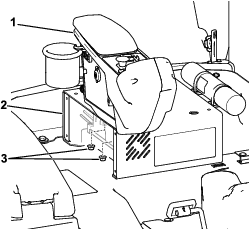
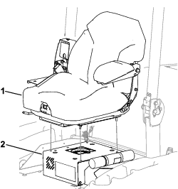
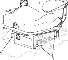
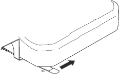
Groundsmaster e3200 or e3300 machines: Remove the plate on the right side of the seat base (Figure 1). Retain the bolts.
-
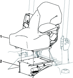
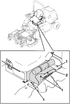
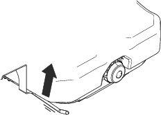
Remove the console from the seat base (Figure 2) and retain the nuts.
Important: Support the console after removing it so that it does not crimp or hang by the cables and wires.
-
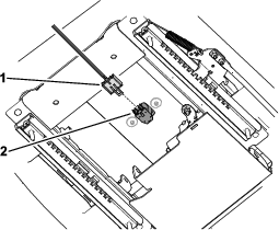
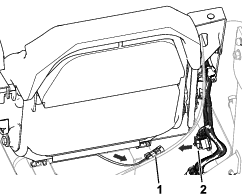
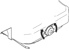
Install the end of the seat-switch wire harness labeled P01 to the connector on the bottom of the seat (Figure 3).
-
Align the seat studs with the holes in the seat base.
-
Groundsmaster 3200 or 3300 machines shown in Figure 4
-
Groundsmaster e3200 or e3300 machines shown in Figure 5
-
Routing the Wire Harness
Note: Models 32301 and 32302 are equipped with 1 wire harness (i.e., the seat-switch wire harness). Model 32303 is equipped with 2 wire harnesses (i.e., the seat-switch wire harness and the air-ride-seat wire harness).
-
Installing the Seat-Switch Wire Harness:
-
Perform the following step for your machine:
-
Groundsmaster 3200 or 3300 machines:
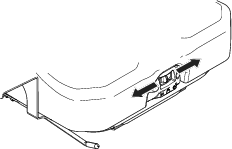
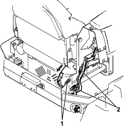
Route the seat-switch wire harness connector between the seat and seat base and toward the machine wire harness (Figure 6).
-
Groundsmaster e3200 or e3300 machines:
Route the seat-switch wire harness connectors above the seat bellows and toward the machine wire harness (Figure 7).
-
-
Install the seat-switch wire harness connectors to the machine wire-harness connectors shown in the following table:
Machine Label—seat-switch wire harness Label—machine wire harness Groundsmaster 3200/3300 P02(SEAT NO) P11(SEAT SWITCH) P03(SEAT NC) Not applicable for these machines. Groundsmaster e3200/e3300 P02(SEAT NO) P79(SEAT SWITCH NO) P03(SEAT NC) P96(SEAT SWITCH NC)
-
-
Installing the Air-Ride-Seat Wire Harness (Model 32303 only):
Install the end of the air-ride-seat wire harness to the machine wire-harness connector shown in the following table:
Machine Label—machine wire harness Groundsmaster 3200/3300 P08(AIR RIDE SEAT SW) Groundsmaster e3200/e3300 P81(AIR RIDE SEAT)
Completing the Installation
-
Perform the following steps for your machine:
-
Groundsmaster 3200 or 3300 machines:
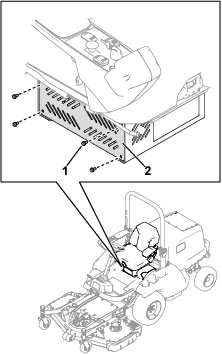
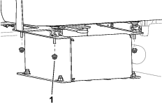
Use 4 nuts to secure the seat to the seat base (Figure 8).
-
Groundsmaster e3200 or e3300 machines:
-
-
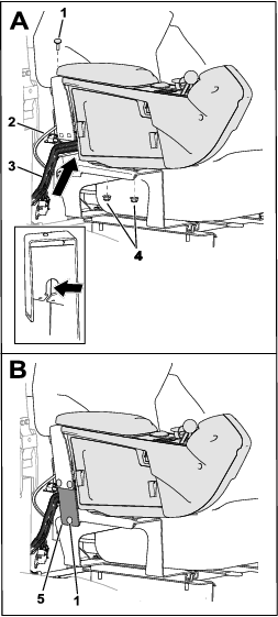
Position the console to the seat bracket (A in Figure 11).
For Model 31900, 31901, 31907, and 31909 machines: Ensure that the throttle cable is positioned in the seat-bracket gap above the wire harness (inset of A in Figure 11).
-
Secure the console to the seat bracket with the existing nuts [removed in Positioning the Seat Assembly] and a carriage bolt and nut (A in Figure 11).
Tighten the carriage bolt and nut, then tighten the existing nuts to the console studs.
-
Secure the plate to the seat bracket with 3 carriage bolts and 3 nuts (B in Figure 11).
Completing the Installation
-
Perform the following steps for your machine:
-
Groundsmaster 3200 or 3300 machines: Connect the battery; refer to the electrical system maintenance section of your Operator’s Manual.
-
Groundsmaster e3200 or e3300 machines: Turn the battery-disconnect switch to the ON position.
-
-
Adjust the seat as needed; refer to Product Overview.
Product Overview
Fore/Aft Locking Lever
Use the fore/aft adjustment lever to change the forward/rearward position of the seat.
-
Model 32301: Move the lever to the left (Figure 12), move the seat to a comfortable position, and release the locking lever to secure the position of the seat.
-
Model 32302 and 32303: Lift the locking lever to release the seat (Figure 13), move the seat to a comfortable position, and release the locking lever to secure the position of the seat.
Important: The locking lever must secure the operator’s seat at the desired position. The operator’s seat must not move forward or rearward when the seat is locked.
Weight-Adjustment Dial
Adjust the dial (Figure 14) to match your weight (kg or lb).
Suspension-Adjustment Switch
Move the switch (Figure 15) to the left or right to adjust the amount of cushioning.