This product complies with all relevant European directives. For details, please see the Declaration of Incorporation (DOI) at the back of this publication.
Warning
CALIFORNIA
Proposition 65 Warning
The engine exhaust from this product contains chemicals known to the State of California to cause cancer, birth defects, or other reproductive harm.
Battery posts, terminals, and related accessories contain lead and lead compounds, chemicals known to the State of California to cause cancer and reproductive harm. Wash hands after handling.
Safety
Safety and Instructional Decals
 |
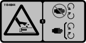
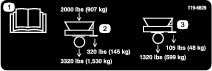
Safety decals and instructions are easily visible to the operator and are located near any area of potential danger. Replace any decal that is damaged or missing. |


Installation
Important: This kit can only be applied to a ProPass that is equipped as a tow-behind machine.
Preparing the Machine
Parts needed for this procedure:
| Hydraulic tank assembly | 1 |
| Hose guide mounting bracket | 1 |
Caution
Installing the kit before disconnecting all external hydraulic and electrical sources may expose you to electric shock and/or pressurized hydraulic fluid, causing serious injury or death.
Before installing the power pack, disconnect all external hydraulic and electrical power sources.
-
Park the machine on a level surface, lower the jack stand, disconnect it from the traction unit, and chock the front and back of the wheels.
-
Following the instructions given in the Operator’s Manual for the machine, remove the Twin Spinner and secure the hydraulic power and return hoses.
Important: Some ProPass models have a pre-drilled chassis rear wall. If your machine has a pre-drilled chassis rear wall, refer to Mounting the Engine.
-
Remove and retain the 2 mounting bolts from the chassis rear wall to allow the hydraulic tank to be mounted.
-
Ensure that the chassis rear wall is clear to mount the hydraulic tank.
-
Remove the hydraulic tank assembly from the crate.
-
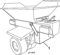
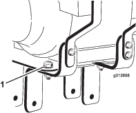
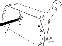
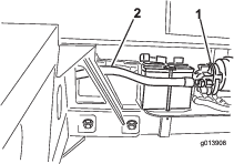
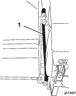
Support the hydraulic tank from underneath and position the tank against the chassis rear wall. The tank should be centered evenly from left to right and should be positioned vertically (Figure 1).
-
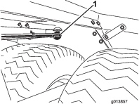
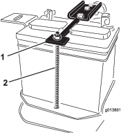
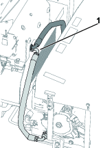
Ensure that the inlet and outlet fittings and the hose guide mounting bracket all fit cleanly within the round holes in the chassis rear wall (Figure 2).
-
Ensure that the hydraulic tank is level.
-
Using C-clamps, or similar devices, temporarily clamp the hydraulic tank firmly in place on the chassis rear wall.
-
Ensure that the hydraulic tank is still level.
-
Mark the position of the hydraulic tank mounting holes onto the chassis rear wall.
-
Unclamp and remove the hydraulic tank.
-
Center punch the position of the marked holes.
-
Drill a 7/16 inch diameter hole through the chassis rear wall in each marked and punched position.
-
De-burr each hole.
Mounting the Engine
Parts needed for this procedure:
| Engine assembly | 1 |
| Bolt (1/2 x 5 inches) | 2 |
| Battery | 1 |
| Battery hold down | 1 |
| Battery mount strap | 1 |
| Battery bolt | 2 |
| Battery bolt spacer | 2 |
| Washer | 2 |
| Flange nut | 2 |
-
Ensure that the hitch tube is clean and free from dirt or debris.
-
Unpack the engine assembly.
-
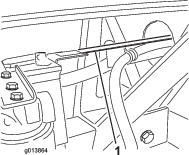
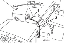
Loosen, but do not remove, the 2 bolts and nuts securing the engine mount brackets to the engine mounting plate (Figure 3).
-
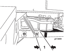
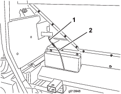
Remove the 2 nuts holding the battery hold down straps in place and set the nuts, washers and bolt tube off to the side (Figure 4).
-
Remove the battery from its position on the assembly and rest the filter on the base plate.
-
Charge the battery; refer to Activating and Charging the Battery.
-
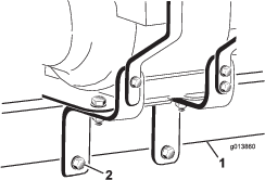
Have someone help you to position the engine assembly onto the hitch tube.
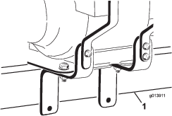
Ensure that the engine mount brackets straddle the hitch tube (Figure 5) and that the rear of the engine mount plate is approximately 25 mm (1 inch) from the hitch tube receiver (Figure 6).
-
Insert the 2 bolts (1/2 x 5 inches) through the engine mount bracket holes, ensuring that a flat washer is fitted against each outer face of the engine mount bracket, and ensuring that the bolts pass beneath the bottom of the hitch tube. Hand tighten the 2 nuts (1/2 inch) as shown in Figure 7.
-
Adjust the engine mount bracket so that it is tight to the hitch. Fully tighten the 2 bolts that you loosened in step 3.
-
Ensure that the engine mounting plate is level and fully tighten the 2 bolts (1/2 x 5 inches) through the engine mount bracket lower holes.
-
Place the battery onto the battery tray, positioning the terminals as shown in Figure 8.
-
Position the battery hold down on the battery (Figure 8).
-
Hold the battery mount strap around the underside of the hitch tube (Figure 8).
-
On the right side, install a battery bolt through the washer, battery mount strap, engine mount plate, battery tray, battery bolt spacer, and hold down. Loosely install a flange nut (Figure 8).
Note: Ensure that the bolts are installed from the bottom.
-
On the left side, install a battery bolt through the washer, battery mount strap, engine mount plate, battery tray, battery bolt spacer, and hold down. Loosely install a flange nut (Figure 8).
-
Ensure that everything is concentric and tighten the nuts.

Installing the Hydraulic System
Parts needed for this procedure:
| Hose guide | 1 |
| Hydraulic return hose (hose #3) | 1 |
| Hydraulic suction hose (hose #4) | 1 |
| Bolt (1/4 x 3/4 inch) | 4 |
| Locknut (1/4 inch) | 4 |
| Bolt (3/8 x 1 inch) | 4 |
| Locknut (3/8 inch) | 4 |
| Flat washer | 4 |
-
Unpack the hose guide, hydraulic return hose (hose #3), hydraulic suction hose (hose #4), 4 bolts (1/4 x 3/4 inch) and 4 locknuts (1/4 inch).
Note: Remove the hose secured to the hose guide, hydraulic return hose and hydraulic suction hose for shipping.
-
Using 2 bolts (1/4 x 3/4 inch) and flange locknuts, attach the hose guide to the bracket on the hydraulic tank (Figure 9).
Note: Remove the 2 mounting bolts must from the chassis rear wall. Use the removed bolts to mount the tank.
-
Unpack 4 bolts (3/8 x 1 inch) and nylon locknuts. Supporting the hydraulic tank from below, pass the hose guide and hydraulic hoses #3 and #4 through the large central hole in the chassis rear wall and locate the hydraulic tank against the chassis rear wall. Temporarily clamp, or bolt, the hydraulic tank in place.
Note: The hose guide should be fed through the center hole on the front side of the chassis. 2 people may be required.
-
Install the hydraulic return hose (#3) and the hydraulic suction hose (#4) to the appropriate fittings on the hydraulic tank.
Note: Hose #3 and hose #4 do not have the same fittings; each hose will fit only into the correct fitting in the hydraulic tank.
Note: When mounting the hoses, ensure that there is adequate clearance for the tires.
-
The hose guide should sit on top of the tab from the vertical leg of the battery tray (Figure 10). If the holes in the hose guide do not match the holes in the battery tray tab, the hose guide length may be adjusted by loosening the bolts attaching the hose guide to the hydraulic tank bracket and sliding the hose guide forward or to the rear as required.
-
Attach the hose guide to the battery tray tab using 2 bolts (1/4 x 3/4 inch) and flange locknuts (Figure 10).
-
Mount the hydraulic tank to the chassis rear wall using the previously removed mounting bolts, as well as the bolts (3/8 x 1 inch), nylon locknuts, and flat washers from the kit, Tighten the fasteners.
-
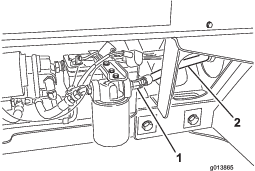
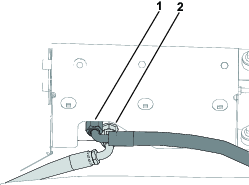
Connect hydraulic hose #3 to the filter outlet (Figure 11).
-
Connect hydraulic hose #4 to the suction side of the hydraulic pump (Figure 12).
-
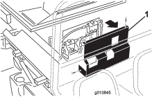
On the SH version (Model 44701) remove the fasteners securing the cover to the front of the machine and set the cover aside (Figure 13).
-
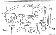
Identify the pressure and return connections on the machine base model. Refer to Figure 14 for the SH versions and Figure 15 for the EH versions.
-
If pressure and return hoses were previously installed at the locations shown in Figure 14 and Figure 15, remove them.
Note: Ensure that the hoses do not contact any hot, sharp, or moving parts. Try to attain as much clearance from the muffler as possible.
-
Connect the hydraulic hoses to the hydraulic control panel. Refer to Figure 14 and Figure 16 on the SH versions and Figure 15 and Figure 17 on the EH versions.
-
Tighten all of the hydraulic connections and fasteners.
Completing the Installation
-
Refit the Twin Spinner assembly.
-
Connect the black cable and the black pre-routed cable to the battery negative terminal and the white cable and the red pre-routed cable to the battery positive terminal.
-
Plug the intermediate wire harness into the power harness connector on the machine (Figure 18 or Figure 19).
-
Fill the engine with approximately 1 L (34 fl oz) of the proper viscosity oil before starting; refer to Servicing the Engine Oil.
Important: The engine is shipped from the factory without oil; attempting to start the machine before you fill it with oil will cause engine damage.
-
Check the level of oil before the engine is first started; refer to Servicing the Engine Oil.
-
Fill the hydraulic tank with the proper hydraulic fluid; refer to Servicing the Hydraulic System.
Important: The hydraulic system will not completely fill with fluid until the system is powered up. Check the hydraulic fluid level and add fluid as necessary to ensure that it is at the correct level after using the hydraulic system for the first time.
Operation
Caution
Ensure that all control systems are turned off when working on the power pack.
Servicing the Engine Oil
Important: The engine is shipped without oil. Refer to the engine owner’s manual for additional information.
The engine is shipped from the factory without oil; it must be filled with approximately 1 L (34 fl oz) of oil before starting.
Check the level of oil before the engine is first started and daily thereafter.
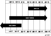
The engine uses any high-quality oil having the American Petroleum Institute - APl - “service classification" SJ, SL or equivalent. Oil viscosity - weight - must be selected according to ambient temperature. Figure 20 illustrates the temperature/viscosity recommendations.
-
Position the machine so that the engine is level.
-
Clean the area around the oil filler cap/dipstick.
-
Remove the oil filler cap/dipstick by rotating it counterclockwise.
-
Wipe the dipstick clean and insert it into the filler port. Do not screw it into the port.
-
Remove the dipstick and check the level of the oil.
-
If the level is near or below the lower limit mark on the dipstick, add only enough oil to raise level to the upper limit mark.
Important: Do not overfill the crankcase.
-
Check the engine oil level again.
-
Install the oil filler cap/dipstick and wipe up any spilled oil.
Important: Ensure that the engine oil is at the proper level. If the engine oil level is not correct, the engine will crank but will not start.
Servicing the Hydraulic System
The machine is shipped from the factory without hydraulic fluid; you must fill it with 32.9 L (8.7 US gallons) of high quality hydraulic fluid. Check the level of hydraulic oil before the machine is first started and daily thereafter. The recommended hydraulic fluids are as follows:
| Toro Premium Transmission/Hydraulic Tractor Fluid (Available in 5 gallon pails or 55 gallon drums. See parts catalog or Toro distributor for part numbers.) |
Alternate fluids: If the Toro fluid is not available, other petroleum-based Universal Tractor Hydraulic Fluids (UTHF) may be used provided its specifications fall within the listed range for all the following material properties and it meets industry standards. We do not recommend the use of synthetic fluid. Consult with your lubricant distributor to identify a satisfactory product.
Important: The hydraulic system will not completely fill with fluid until the system is powered up. Check the hydraulic fluid level and add fluid as necessary to ensure that it is at the correct level after using the hydraulic system for the first time.
Note: Toro will not assume responsibility for damage caused by improper substitutions, so use only products from reputable manufacturers who will stand behind their recommendation.
| Material Properties: | |||
| Viscosity, ASTM D445 | cSt @ 40° C 55 to 62cSt @ 100° C 9.1 to 9.8 | ||
| Viscosity Index ASTM D2270 | 140 to 152 | ||
| Pour Point, ASTM D97 | -35° F to -46° F | ||
| Industry Specifications: | |||
| API GL-4, AGCO Powerfluid 821 XL, Ford New Holland FNHA-2-C-201.00, Kubota UDT, John Deere J20C, Vickers 35VQ25, and Volvo WB-101/BM | |||
Note: Many hydraulic fluids are almost colorless, making it difficult to spot leaks. A red dye additive for the hydraulic system oil is available in 2/3 oz (20 ml) bottles. One bottle is sufficient for 15 to 22 L (4 to 6 US gallons) of hydraulic oil. Order part number 44-2500 from your Authorized Toro Distributor.
Fuel Safety
-
Use extreme care in handling fuel. It is flammable and its vapors are explosive.
-
Extinguish all cigarettes, cigars, pipes, and other sources of ignition.
-
Use only an approved fuel container.
-
Do not remove the fuel cap or fill the fuel tank while the engine is running or hot.
-
Do not add or drain the fuel in an enclosed space.
-
Do not store the machine or fuel container where there is an open flame, spark, or pilot light, such as on a water heater or other appliance.
-
If you spill fuel, do not attempt to start the engine; avoid creating any source of ignition until the fuel vapors have dissipated.
Filling the Fuel Tank
Fuel Tank Capacity: 6.1 L (1.6 US gallons)
Recommended Fuel:
-
For best results, use only clean, fresh (less than 30 days old), unleaded gasoline with an octane rating of 87 or higher (R+M)/2 rating method).
-
Ethanol: Gasoline with up to 10% ethanol (gasohol) or 15% MTBE (methyl tertiary butyl ether) by volume is acceptable. Ethanol and MTBE are not the same. Gasoline with 15% ethanol (E15) by volume is not approved for use. Never use gasoline that contains more than 10% ethanol by volume, such as E15 (contains 15% ethanol), E20 (contains 20% ethanol), or E85 (contains up to 85% ethanol ). Using unapproved gasoline may cause performance problems and/or engine damage which may not be covered under warranty.
-
Do not use gasoline containing methanol.
-
Do not store fuel either in the fuel tank or fuel containers over the winter unless a fuel stabilizer is used.
-
Do not add oil to gasoline.
Activating and Charging the Battery
Use only electrolyte (1.265 specific gravity) to fill battery initially.
-
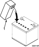
Clean the top of the battery and remove the vent caps (Figure 21).
Important: Do not add electrolyte while the battery is in the machine. You could spill it, causing corrosion.

-
Carefully fill each cell with electrolyte until the plates are covered with about 6 mm (1/4 inch) of fluid (Figure 22).
-
Allow approximately 20 to 30 minutes for the electrolyte to soak into the plates. Refill as necessary to bring the electrolyte to within about 6 mm (1/4 inch) of the bottom of the fill well (Figure 22).
Warning
Charging the battery produces gasses that can explode.
Never smoke near the battery and keep sparks and flames away from battery.
-
Connect a 3 to 4 amp battery charger to the battery posts. Charge the battery at a rate of 3 to 4 amps until the specific gravity is 1.250 or higher and the temperature is at least 16° C (60° F) with all cells gassing freely.
-
When the battery is charged, disconnect the charger from the electrical outlet and battery posts.
Note: After the battery has been activated, add only distilled water to replace normal loss, although maintenance-free batteries should not require water under normal operating conditions.
Warning
Battery terminals or metal tools could short against metal tractor components causing sparks. Sparks can cause the battery gasses to explode, resulting in personal injury.
-
When removing or installing the battery, do not allow the battery terminals to touch any metal parts of the tractor.
-
Do not allow metal tools to short between the battery terminals and metal parts of the tractor.
-
Operating Tips
-
Connect the clevis hitch to the tow vehicle. Use a high-strength hitch pin approved for tow vehicles.
-
Turn on the fuel valve, place the throttle lever at half throttle, engage the choke, and start the engine. Once the engine starts, turn off the choke and increase the throttle to maximum.
-
Test the machine operation. Ensure that there are no hydraulic leaks and make any additional adjustments.
-
After testing the hydraulic system, check the hydraulic fluid and add more if required.
Note: Ensure that the pendant and any cords do not drag on the ground during operation.