The Energy Expansion Mounting Kit allows you to install 2 additional HyperCell® batteries to a machine equipped with 15 batteries, resulting in a total of 17 batteries.
Safety
Refer to your traction unit Operator’s Manual for electrical system safety information.
Installation
Preparing the Machine
-
Park the machine on a level surface.
-
Ensure that the parking brake is engaged; refer to your traction unit Operator's Manual.
-
Shut off the machine and remove the key.
-
Turn the battery-disconnect switch to the OFF position.
-
Raise the hood.
-
Use a digital multimeter to measure the voltage across the positive and negative bus bars.
The voltage should be less than 1 VDC. If the voltage is above 1 VDC, ensure that the key switch is in the OFF position and the battery-disconnect switch is in the OFF position, then check the voltage again. If the voltage is still above 1 VDC, there may be a battery fault; refer to the traction unit Service Manual or your authorized Toro distributor.
Installing the Battery Tray
Parts needed for this procedure:
| Battery tray | 1 |
| Carriage bolt (5/16 inch) | 4 |
| Hex-flange nut | 4 |
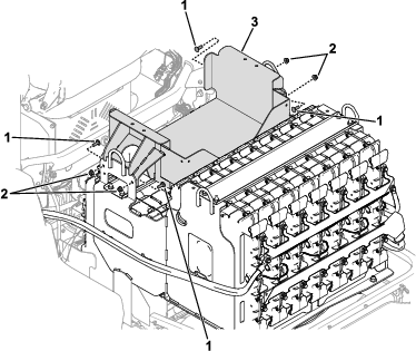
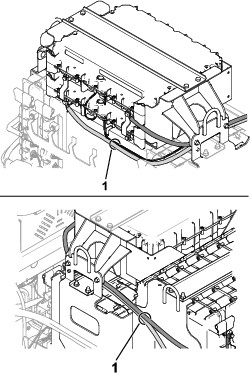
Use 4 carriage bolts (5/16 inch) and 4 hex-flange nuts to secure the battery tray to the battery-compartment frame (Figure 1).
Installing the Batteries
Parts needed for this procedure:
| HyperCell battery (sold separately; refer to your authorized Toro distributor) | 2 |
| Hex-head bolt (1/4 inch) | 4 |
| Bus bar | 2 |
| Red battery cable | 1 |
| Black battery cable | 1 |
| Wire harness (data interface—7-1/2 inches) | 1 |
| Wire harness (data interface—45-1/2 inches) | 1 |
| Battery cover | 1 |
| Foam pad | 2 |
| Hex-head bolt (5/16 inch) | 4 |
| Washer (5/16 inch) | 4 |
| Hex-flange nut | 4 |
| Push fastener | 1 |
| Carriage bolt (1/4 inch) | 2 |
| Washer (1/4 inch) | 2 |
| Locknut | 2 |
| Cable tie | 2 |
Installing the Battery Cables
-
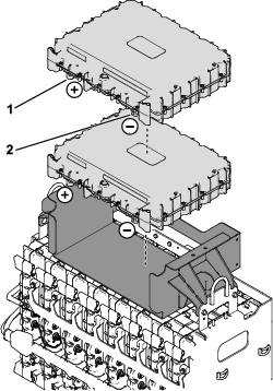
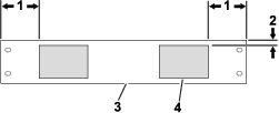
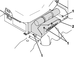
Place 2 batteries in the battery tray (Figure 2).
-
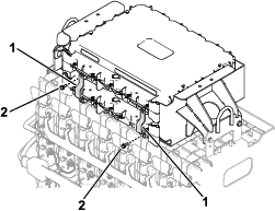
Use 2 hex-head bolts (1/4 inch) to loosely secure the bus bars to the batteries (Figure 3).
-
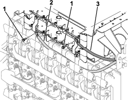
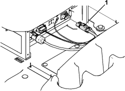
Use 2 hex-head bolts (1/4 inch) to connect the red and black battery cables to the bus bars that you installed in the previous step (Figure 4).
Important: Loosely install the hex-head bolts to the cables and bus bars. You will torque the bolts in a later step.
-
Verify that the bus bars are seated properly and torque the hex-head bolts (Figure 3 and Figure 4) to 11 N·m (95 in-lb).
-
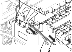
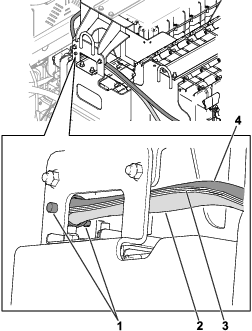
Route the battery cables toward the rear battery tray as shown in Figure 4 and Figure 5.
Important: Ensure that the cables are routed away from pinch points or sharp edges.
-
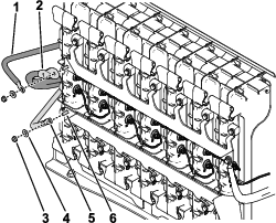
Use 2 carriage bolts (1/4 inch), washers (1/4 inch), and 2 locknuts to connect the red and black battery cables to the bus bars at the rear battery tray as shown in Figure 6.
Torque the hardware to 10.8 N·m (8 ft-lb).
Note: The black battery cable in the kit is installed on top of the existing black battery cable on the machine as shown in Figure 6.
Installing the Wire Harnesses
-
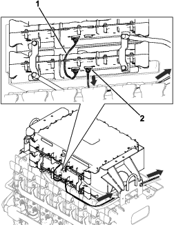
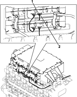
Connect the wire harnesses to the batteries as shown in Figure 7.
-
Route the remaining connector of the data-interface wire harness (45-1/2 inches) toward the rear battery tray (Figure 7).
-
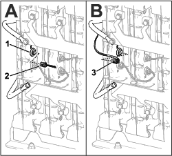
Remove the existing wire harness (CAN) from the D2 battery port (Figure 8). Retain the wire harness.
-
Install the remaining connector of the data-interface wire harness to the D2 battery port (Figure 8).
-
Install the wire harness (CAN) that you removed in step 3 to the D2 battery port on the top battery in the battery tray (Figure 9).
-
Use a push fastener to secure the battery cables and data-interface wire harness to the battery tray (Figure 10).
-
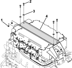
Install the foam pads to the battery cover as shown in Figure 11.
-
Use 4 hex-head bolts (5/16 inch), 4 washers (5/16 inch), and 4 hex-flange nuts to secure the battery cover to the battery tray (Figure 12).
Installing Cable Ties to the Wire Harness and Battery Cables
Important: Before you install the cable ties, ensure that the wire harness and cables are routed away from any moving or sharp parts.
Use 2 cable ties to secure the wire harness and battery cables together in the areas shown in Figure 13.
Using Toro DIAG to Configure and Verify Battery Settings
Preparing to Use Toro DIAG
Using Toro DIAG to Configure the Battery Settings
-
Connect Toro DIAG to the machine; refer to the Toro DIAG Commercial Product User’s Guide.
-
Ensure that the software revision level for the batteries is updated by selecting the REPROGRAM button in Toro DIAG; refer to the Toro DIAG Software User’s Guide.
-
Turn the battery-disconnect switch to the ON position.
-
Within Toro DIAG, select PRIMARY CONTROLLER, navigate to the CONFIG tab, then enter number of batteries that are equipped on the machine in the NUMBER OF BATTERIES field.
-
Disconnect Toro DIAG from the machine.
Verifying the Battery Settings
-
Turn the battery-disconnect switch to the OFF position.
-
Install the DC power connector to the charger (Figure 15).
-
Install the charger-cable cover (Figure 14).
-
Turn the battery-disconnect switch to the ON position.
-
Charge the batteries; refer to your machine Operator’s Manual.
-
Perform the following steps to verify the number of active batteries on the machine:
-
Use the machine display screen to navigate to the DIAGNOSTICS menu.
-
Navigate to the BATTERIES menu item, select OUTPUTS, then select NUMBER OF PACKS.
-
Verify that the number shown in the NUMBER OF PACKS screen matches the number of batteries that are equipped on the machine.
-
Completing the Installation
-
Verify that the battery-disconnect switch is in the ON position.
-
Verify that there are no fault codes displayed on the machine display.
-
If the display shows a U1311 fault code, the battery software does not match the machine software and the software needs to be reprogrammed using the current release of Toro DIAG.
-
If the display shows a U1151 fault code, the number of batteries on the machine does not match the amount of batteries that were configured in Toro DIAG. Connect the machine to Toro DIAG and ensure that the number of batteries on the machine matches the amount of batteries listed in Toro DIAG.
Refer to your authorized Toro distributor for any needed assistance.
-