Installation
Preparing the Machine
-
Park the machine on a level surface.
-
Shut off the engine, engage the parking brake, and remove the key.
-
Disconnect the battery; refer to the electrical system maintenance section of the traction unit Operator’s Manual.
-
Ensure that the following kits are installed to your machine:
-
Universal Sunshade (Model 30671 or 30669)
-
Switch Panel Kit (Model 03248)
-
Power Harness Kit; refer to the following table for the appropriate kit for your traction unit:
Traction Unit Power Harness Kit Reelmaster 3000 series 138-2993 Reelmaster 5000 series 138-2994 Groundsmaster 4500, 4700 and Reelmaster 7000 series 138-2995 Groundsmaster 7200 series 138-2996 Multi Pro 1750 138-2999 Groundsmaster 5900 series 138-3002
-
Removing the Sunshade


Installing the Beacon
Parts needed for this procedure:
| Beacon | 1 |
| Beacon connector | |
| Beacon bracket | 1 |
| Beacon socket | 1 |
| Long carriage bolt | 1 |
| Short carriage bolt | 1 |
| Flange nut | 2 |
| Wire harness | 1 |
| Cable ties | 6 |
| Switch | 1 |
| Fuse (15 A) | 1 |
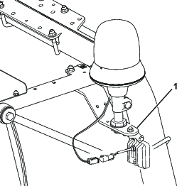
Note: The illustrations in this procedure show a Reelmaster 5010 series traction unit. Your machine may look different.
-
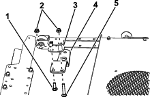
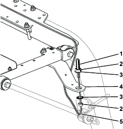
Secure the bracket to the sunshade frame with a long carriage bolt, short carriage bolt, spacer, and 2 flange nuts.
Note: If your machine has a work light kit installed, use the light bracket instead of the beacon bracket (Figure 4).
-
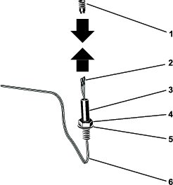
Remove the beacon connector from the beacon socket (Figure 5).

-
Route the wire harness up through the nut, washer, and beacon socket. Connect the terminals to the beacon connector (Figure 6).
Note: Install the violet wire to the center terminal on the beacon connector and the black wire on the outside of the terminal on the beacon connector.
-
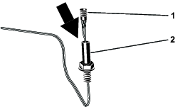
Install the beacon connector into the beacon socket by rotating the beacon socket (Figure 7).
Note: This prevents the wire harness from becoming twisted.
-
Install the beacon socket to the bracket as shown in Figure 8.
Note: If your machine has a work light kit installed, use the light bracket instead of the beacon bracket (Figure 4).
-
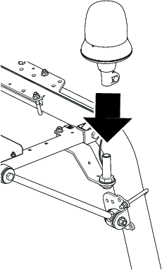
Install the beacon to the socket, and tighten the wing nut (Figure 9).
-
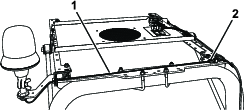
Plug the connector on the beacon harness into the connector on the switch-panel harness (Figure 10).
-
Route the beacon harness as shown in Figure 10 and secure with cable ties.
-
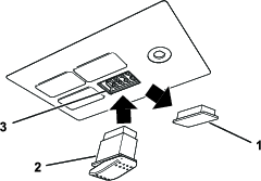
Remove and discard the plug from the front left space in the switch panel (Figure 11).
Note: Install the switch so that the thicker, rounded part is toward the rear of the machine
-
Plug the electrical connector into the switch and install the switch into the switch panel (Figure 11).
-
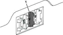
Insert the fuse (15 A) into the third position from the left when looking at the fuse block (Figure 12).
Note: The fuse may not need to be installed if a fuse has already been installed from another Toro kit.
Connecting the Battery
Connect the battery; refer to the electrical system maintenance section of your Operator’s Manual.
Installing the Sunshade
-
Align the holes in the grommets of the sunshade with the 4 clip nuts of the side-frame channels.
-
Assemble the sunshade to the frame channels (Figure 2) with the 4 flange-head bolts (5/16 x 1-1/4 inches) and 4 washers (5/16 inch) that you removed earlier.
-
Torque the flange-head bolts to 10 to 14 N∙m (90 to 120 in-lb).
Operation
Using the Beacon
With the key in the ON position:
-
Press the back of the switch to turn on the beacon.
-
Press the front of the switch to turn off the beacon.