Note: The ProStripe 560 mower is shown in the graphics for these Installation Instructions. The eProStripe 560 60V mower has a different visual appearance, but the installation process for this kit is the same for both mowers.

Safety

Safety and Instructional Decals

Graphic

Safety decals and instructions are easily visible to the operator and are located near any area of potential danger. Replace any decal that is damaged or missing.

decal134-3990

Installation

Preparing the Machine

Warning

The blade is sharp; contacting the blade can result in serious personal injury.

Wear gloves when servicing the blade.
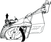
Warning

Tipping the machine may cause the fuel to leak. Fuel is flammable and explosive, and can cause personal injury.

Run the engine dry or remove the fuel with a hand pump; never siphon the fuel.

Important: Do not add fuel to the fuel tank prior to installing the brush kit.

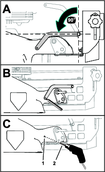
For the ProStripe 560 mower:

  1. Run the engine to empty the fuel tank or remove the fuel with a hand pump.

    If you do not use all the fuel in the tank, use a hand fuel pump to remove the fuel.

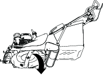
  2. Move the machine to a level surface, ensure that the engine is shut off, and wait for all moving parts to stop.

  3. Disconnect the spark-plug wire from the spark plug; refer to the Operator’s Manual for your machine.

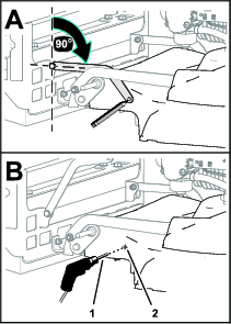
For the eProStripe 560 60V mower:

  1. Move the machine to a level surface, shut off the machine, and wait for all moving parts to stop.

  2. Remove the electric-start button and all battery packs from the machine.

Assembling the Brush Mount

Parts needed for this procedure:

Brush-adjustment bracket1
Groomer brush1
Capscrew (8 x 60 mm)4
Washer (8 mm)8
Locknut (8 mm)4
Brush-height plate2
Carriage bolt (8 x 25 mm)2
Knob2
Strut (brush)2
Capscrew (6 x 20 mm)2
Washer (6 mm)4
Locknut (6 mm)2

Assembling the Groomer Brush to the Brush-Adjustment Bracket

g284576
  1. Align the holes in the brush-adjustment bracket with the holes in the groomer brush as shown in Figure 1.

  2. Assemble the brush-adjustment bracket to the groomer brush (Figure 1) with 4 capscrews (8 x 60 mm), 8 washers (8 mm), and 4 locknuts (8 mm).

  3. Tighten the capscrews and locknuts.

Assembling the Brush-Adjustment Bracket to the Brush Mount

  1. Assemble the brush and brush-adjustment bracket to the brush mount as shown in Figure 2.

    Note: Ensure that the rod ends of the handle for the brush-adjustment bracket align through the slots in the brush mount.

    g284577
  2. Assemble a brush-height plate over the rod end of the handle for the brush-adjustment bracket as shown in Figure 3.

    g284575
  3. Assemble a carriage bolt through the opening in the brush-adjustment bracket, the slot in the brush mount, and the lower hole in the brush-height plate (Figure 3).

  4. Thread a knob onto the carriage bolt, and tighten the knob (Figure 3).

  5. Repeat steps 2 through 4 at the other end of the brush mount.

Assembling the Struts to the Brush Mount

  1. Align the hole in the brush strut with the hole on the tab of the brush mount as shown in Figure 4.

    g284578
  2. Secure the brush strut to the brush mount (Figure 4) with a capscrew (6 x 20 mm), 2 washers (6 mm), and a locknut (6 mm).

  3. Repeat steps 1 and 2 for the brush strut at the other end of the brush mount.

Assembling the Brush Kit to the Machine

Parts needed for this procedure:

Lower brush bracket2
Self-tapping, flange-head screw (6 x 20 mm)4
Capscrew (6 x 20 mm)2
Washer (6 mm)4
Locknut (6 mm)2

Removing the Wheels

  1. Remove the flange locknut (3/8 inch) that secures the wheel to the axle, and remove the wheel (Figure 5).

    g284602
  2. Repeat step 1 for the wheel at the other side of the machine.

Removing the Front Fins

  1. Tip the machine onto its side with the air filter or height-of-cut lever up (Figure 6).

    g283871
  2. Remove the 7 self-tapping, flange-head screws (6 x 20 mm) that secure the front fins to the supports of the mower deck, and remove the front fins (Figure 7).

    Note: You will not use these front fins with the groomer brush kit.

    g284601

Assembling the Lower Brush Brackets to the Machine

  1. Align the holes in the lower brush bracket with the holes in the groomer brush support of the mower deck as shown in Figure 8.

    g284634
  2. Secure the lower brush bracket to the groomer brush support (Figure 8) with 2 self-tapping, flange-head screws (6 x 20 mm).

  3. Repeat steps 1 and 2 for the other lower brush bracket at the other side of the machine.

  4. Carefully lower the machine (Figure 9).

    g284636

Assembling the Groomer Brush to the Lower Brush Brackets

  1. Assemble a capscrew (6 x 20 mm) and washer (6 mm) through the hole in the brush mount (Figure 10).

    g284658
  2. Assemble the other capscrew (6 x 20 mm) and washer (6 mm) through the other hole in the brush mount (Figure 10).

  3. Align the capscrews that you assembled in steps 1 and 2 through the holes of the lower brush brackets as shown in Figure 11.

    g284657
  4. Assemble the brush mount and capscrews to the lower brush brackets (Figure 11) with 2 washers (6 mm) and 2 locknuts (6 mm).

  5. Tighten the capscrews and locknuts.

Installing the Brush Struts to the Machine

Parts needed for this procedure:

Capscrew (6 x 20 mm)2
Washer (6 mm)4
Locknut (6 mm)2

Drilling the Deck for the Right Brush Strut

  1. At the right side of the mower deck, align the brush strut 90° to the to the brush mount (Figure 12).

    g284670
  2. Mark the hole location of the brush strut onto the deck (Figure 12).

  3. Move the strut up and centerpunch the midpoint of the mark that you made in step 2.

  4. Drill the centerpunch mark with a drill bit (6.5 mm) as shown in Figure 12.

    Warning

    Using a drill without proper eye protection may allow debris to enter the eye, causing injury.

    When drilling, always wear eye protection.

  5. Remove any burrs from the hole.

Assembling the Right Brush Strut to the Machine

  1. Align the hole in the brush strut with the hole in the deck.

    g284669
  2. Assemble the brush strut to the mower deck (Figure 13) with a capscrew (6 x 20 mm), 2 washers (6 mm), and a locknut (6 mm).

  3. Tighten the capscrew and locknut.

Drilling the Deck for the Left Brush Strut

  1. At the left side of the mower deck, align the brush strut 90° to the to the brush mount (Figure 14).

    g284728
  2. Mark the hole location of the brush strut onto the deck (Figure 14).

  3. Move the strut up and centerpunch the midpoint of the mark that you made in step 2.

  4. Drill the centerpunch mark with a drill bit (6.5 mm) as shown in Figure 14.

  5. Remove any burrs from the hole.

Assembling the Left Brush Strut to the Machine

  1. Align the hole in the brush strut with the hole in the deck (Figure 15).

    g284725
  2. Assemble the brush strut to the mower deck (Figure 15) with a capscrew (6 x 20 mm), 2 washers (6 mm), and a locknut (6 mm).

  3. Tighten the capscrew and locknut.

Installing the Front Fins and the Wheels

Parts needed for this procedure:

Front fins1

Assembling the Front Fins to the Machine

  1. Align the holes in the new front fin with the holes in the supports of the mower deck (Figure 16).

    g285247
  2. Assemble the front fins to the mower deck (Figure 16) with the 7 self-tapping, flange-head screws (6 x 20 mm) that you removed in Removing the Front Fins.

  3. Tighten the self-tapping, flange-head screws.

Assembling the Wheels to the Machine

  1. Assemble a wheel onto the axle with the flange locknut (3/8 inch) that you removed in Removing the Wheels.

    g284727
  2. Tighten the locknut.

  3. Repeat steps 1 and 2 for the wheel at the other side of the machine.

Finishing the Kit Installation

Add fuel to the fuel tank or battery packs to the battery compartment; refer to the Operator’s Manual for your machine.

Operation

Adjusting the Brush Angle

  1. Loosen the knobs at the sides of the brush mount (Figure 18).

    g284762
  2. Use the handle of the brush-adjustment bracket to adjust the angle of the groomer brush (Figure 18).

    Note: Tilting the brush forward increases its aggressiveness. Tilting the brush rearward decreases its aggressiveness.

  3. Tighten the knobs (Figure 18).

Adjusting the Brush Height

  1. Loosen the knobs at the sides of the brush mount (Figure 19).

    g284761
  2. Use the handle of the brush-adjustment bracket to raise or lower the groomer brush (Figure 19).

    Note: Ensure that the brush-height plate points to the same height number at both sides of the brush mount.

  3. Tighten the knobs (Figure 19).

Maintenance

Replacing the Brush

  1. Remove the 4 capscrews (8 x 60 mm), 8 washers (8 mm), and 4 locknuts (8 mm) that secure the groomer brush to the brush-adjustment bracket, and remove the brush (Figure 20).

    g284816
  2. Align the holes in the new groomer brush with the holes in the brush-adjustment bracket (Figure 20).

  3. Assemble the brush to the bracket (Figure 20) with the 4 capscrews (8 x 60 mm), 8 washers (8 mm), and 4 locknuts (8 mm) that you removed in step 1.

  4. Tighten the capscrews and locknuts.