


Maintenance
Note: Determine the left and right sides of the machine from the normal operating position.
Maintenance Safety
-
Park machine on level ground, disengage drives, set parking brake, stop engine, and remove key. Wait for all moving parts to stop before leaving the operator’s position. Allow the machine to cool before servicing, adjusting, fueling, cleaning, or storing.
-
If you leave the key in the switch, someone could accidently start the engine and seriously injure you or other bystanders. Remove the key from the switch before you perform any maintenance.
-
Never allow untrained personnel to service machine.
-
Disconnect battery or remove spark plug wire before making any repairs. Disconnect the negative terminal first and the positive last. Reconnect positive first and negative last.
-
Keep all guards, shields, switches, and all safety devices in place and in proper working condition. Frequently check for worn or deteriorating components and replace them with genuine Exmark parts when necessary.
Warning
Removal or modification of original equipment, parts and/or accessories may alter the warranty, controllability, and safety of the machine. Unauthorized modifications to the original equipment or failure to use original Exmark parts could lead to serious injury or death. Unauthorized changes to the machine, engine, fuel or venting system, may violate applicable safety standards such as: ANSI, OSHA and NFPA and/or government regulations such as EPA and CARB.
Warning
Hydraulic fluid escaping under pressure can penetrate skin and cause injury. Fluid accidentally injected into the skin must be surgically removed within a few hours by a doctor familiar with this form of injury or gangrene may result.
-
If equipped, make sure all hydraulic fluid hoses and lines are in good condition and all hydraulic connections and fittings are tight before applying pressure to hydraulic system.
-
Keep body and hands away from pinhole leaks or nozzles that eject high pressure hydraulic fluid.
-
Use cardboard or paper, not your hands, to find hydraulic leaks.
-
Safely relieve all pressure in the hydraulic system by placing the motion control levers in neutral and shutting off the engine before performing any work on the hydraulic system.
For EFI (Electronic Fuel Injection) Models:
Warning
Fuel system components are under high pressure. The use of improper components can result in system failure, gasoline leakage and possible explosion.
Use only approved fuel lines and fuel filters for high pressure systems.
-
-
Use care when checking blades. Wrap the blade(s) or wear gloves, and use caution when servicing them. Only replace damaged blades. Never straighten or weld them.
-
Do not rely solely on mechanical or hydraulic jacks for support. Use adequate jack stands.
-
Carefully release pressure from components with stored energy.
-
Keep your hands and feet away from moving parts or hot surfaces. If possible, do not make adjustments with the engine running.
-
Keep all parts in good working condition and all hardware tightened, especially the blade-attachment hardware.
Recommended Maintenance Schedule(s)
| Maintenance Service Interval | Maintenance Procedure |
|---|---|
| After the first 5 hours |
|
| After the first 100 hours |
|
| After the first 250 hours |
|
| Before each use or daily |
|
| Every 50 hours |
|
| Every 100 hours |
|
| Every 200 hours |
|
| Every 250 hours |
|
| Every 400 hours |
|
| Every 500 hours |
|
| Every 600 hours |
|
| Yearly |
|
| Yearly or before storage |
|
Periodic Maintenance
Engine Maintenance
Important: For Kawasaki, Briggs, and Kohler Engines, refer to the Engine Owner’s Manual for additional maintenance procedures.
Engine Safety
Warning
The engine can become very hot, especially the muffler and exhaust components. Touching a hot engine can cause severe burns.
Allow the engine to cool completely before service or making repairs around the engine area.
Do Not change the engine governor setting or overspeed the engine.
Check Engine Oil Level
| Maintenance Service Interval | Maintenance Procedure |
|---|---|
| Before each use or daily |
|
-
Stop engine and wait for all moving parts to stop. Make sure unit is on a level surface.
-
Check with engine cold.
-
Clean area around dipstick. Remove dipstick and wipe oil off. Reinsert the dipstick according to the engine manufacturer's recommendations. Remove the dipstick and read the oil level.
-
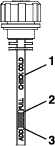
If the oil level is low, wipe off the area around the oil fill cap, remove cap and fill to the “FULL” mark on the dipstick. Exmark 4-Cycle Premium Engine Oil is recommended; refer to the Engine Owner's manual for an appropriate API rating and viscosity. Do Not overfill.
Important: Do Not operate the engine with the oil level below the “LOW” (or “ADD”) mark on the dipstick, or over the “FULL” mark.
Check Battery Charge
Allowing batteries to stand for an extended period of time without recharging them will result in reduced performance and service life. To preserve optimum battery performance and life, recharge batteries in storage when the open circuit voltage drops to 12.4 volts.
Note: To prevent damage due to freezing, battery should be fully charged before putting away for winter storage.
Charge batteries in an open well ventilated area, away from spark and flames. Unplug charger before connecting or disconnecting from battery. Wear protective clothing and use insulated tools.
Danger
Charging or jump starting the battery may produce explosive gases. Battery gases can explode causing serious injury.
-
Keep sparks, flames, or cigarettes away from battery.
-
Ventilate when charging or using battery in an enclosed space.
-
Make sure venting path of battery is always open once battery is filled with acid.
-
Always shield eyes and face from battery.
Danger
Battery electrolyte contains sulfuric acid, which is poisonous and can cause severe burns. Swallowing electrolyte can be fatal or if it touches skin can cause severe burns.
-
Wear safety glasses to shield eyes, and rubber gloves to protect skin and clothing when handling electrolyte.
-
Do Not swallow electrolyte.
-
In the event of an accident, flush with water and call a doctor immediately.
Caution
If the ignition is in the “ON” position there is potential for sparks and engagement of components. Sparks could cause an explosion or moving parts could accidentally engage causing personal injury.
Be sure ignition switch is in the “OFF” position before charging the battery.
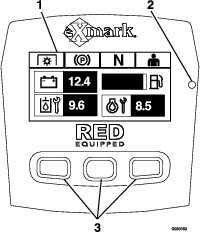
For Kohler, Briggs Non-EFI, and Kawasaki machines: Check the voltage of the battery with a digital voltmeter or with the message display. If the ignition key is turned to the “on” position for a few seconds, the battery voltage will be displayed in the area where the hours are normally displayed. Locate the voltage reading of the battery in the table and charge the battery for the recommended time interval to bring the charge up to a full charge of 12.6 volts or greater.
Important: Make sure the negative battery cable is disconnected and the battery charger used for charging the battery should have an output of 16 volts and 7 amps or less to avoid damaging the battery (see chart for recommended charger settings). This is especially important on Kohler EFI (Electronic Fuel Injection) units. Failure to do so may damage the ECU (Electronic Control Unit).
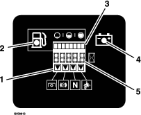
For Briggs EFI machines: Check the voltage of the battery with a digital voltmeter or with the message display. When the ignition is set to accessory mode, the module will display the battery voltage. If the voltage is less than 12.4 volts, the battery may need to be charged.
Important: In order to prevent damage to the battery, use an automatic 12 volt smart charger approved for use with AGM type batteries with an output of 3.5 amps or less. Exmark recommends the use of battery charger P/N 135-7024. Make sure the negative battery cable is disconnected before charging and that the charger is set to the correct mode for 12 volt AGM batteries.
| Voltage Reading | Percent Charge | Maximum Charger Settings | Charging Interval |
|---|---|---|---|
| 12.6 or greater | 100% | 16 volts/7 amps | No Charging Required |
| 12.4 – 12.6 | 75–100% | 16 volts/7 amps | 30 Minutes |
| 12.2 – 12.4 | 50–75% | 16 volts/7 amps | 1 Hour |
| 12.0–12.2 | 25–50% | 14.4 volts/4 amps | 2 Hours |
| 11.7–12.0 | 0–25% | 14.4 volts/4 amps | 3 Hours |
| 11.7 or less | 0% | 14.4 volts/2 amps | 6 Hours or More |
Important: For EFI machines: Unplug the harness from the ECU before performing any welding on the equipment.
Recommended Jump Starting Procedure
-
Check the weak battery for terminal corrosion (white, green, or blue “snow”), it must be cleaned off prior to jump starting. Clean and tighten connections as necessary.
Caution
Corrosion or loose connections can cause unwanted electrical voltage spikes at anytime during the jump starting procedure.
Do Not attempt to jump start with loose or corroded battery terminals or damage to the engine or EFI may occur.
Danger
Jump starting a weak battery that is cracked, frozen, has low electrolyte level, or an open/shorted battery cell, can cause an explosion resulting in serious personal injury.
Do Not jump start a weak battery if these conditions exist.
-
Make sure the booster is a good and fully charged lead acid battery at 12.6 volts or greater. Use properly sized jumper cables (4 to 6 AWG) with short lengths to reduce voltage drop between systems. Make sure the cables are color coded or labeled for the correct polarity.
Caution
Connecting the jumper cables incorrectly (wrong polarity) can immediately damage the electrical and/or EFI system.
Be certain of battery terminal polarity and jumper cable polarity when hooking up batteries.
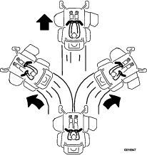
Note: The following instructions are adapted from the SAE J1494 Rev. Dec. 2001 – Battery Booster Cables – Surface Vehicle Recommended Practice (SAE – Society of Automotive Engineers).
Warning
Batteries contain acid and produce explosive gases.
-
Shield the eyes and face from the batteries at all times.
-
Do Not lean over the batteries.
Note: Be sure the vent caps are tight and level. Place a damp cloth, if available, over any vent caps on both batteries. Be sure the vehicles do not touch and that both electrical systems are off and at the same rated system voltage. These instructions are for negative ground systems only.
-
-
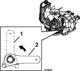
Connect the positive (+) cable to the positive (+) terminal of the discharged battery that is wired to the starter or solenoid as shown in Figure 40.
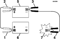
-
Connect the other end of the positive cable to the positive terminal of the booster battery.
-
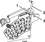
Connect the black negative (–) cable to the other terminal (negative) of the booster battery.
-
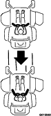
MAKE THE FINAL CONNECTION ON THE ENGINE BLOCK OF THE STALLED VEHICLE (NOT TO THE NEGATIVE POST) AWAY FROM THE BATTERY. STAND BACK (see Figure 41).
-
Start the vehicle and remove the cables in the reverse order of connection (the engine block (black) connection is the first to disconnect).
Note: A malfunctioning machine battery may cause the charging voltage to exceed 18.5 volts. The engine will turn off if there is a charge above 18.5 volts. Turn the ignition switch off, then on again to reset the engine before restarting the machine.
Check Mower Blades
| Maintenance Service Interval | Maintenance Procedure |
|---|---|
| Before each use or daily |
|
-
Stop engine, wait for all moving parts to stop, and remove key. Engage parking brake.
-
Lift deck and secure in raised position as stated in the Clean Grass Build-Up Under Deck section.
-
Inspect blades and sharpen or replace as required.
-
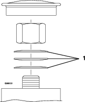
Reinstall the blades (if they were removed) in the following order:
-
Install bushing through blade with bushing flange on bottom (grass) side of blade.
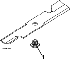
-
Install bushing/blade assembly into spindle. Make sure the splines on the bushing are engaged in the spindle before tightening the bolt.
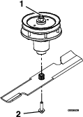
-
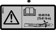
Apply lubricant to threads of blade bolt to prevent seizing. Copper-based anti-seize preferable. Grease acceptable substitute. Install blade bolt finger tight. Place wrench on the top spindle nut then torque the blade bolts to 50-60 ft-lb (68-81 N-m).
Important: On rear discharge decks, the RH blade rotates counterclockwise. Be sure to reinstall that blade onto the RH spindle only.
Warning
Incorrect installation of the blade or components used to retain the blade can be dangerous. Failure to use all original components and assembled as shown could allow a blade or blade component to be thrown out from under the deck resulting in serious personal injury or death.
Always install the original Exmark blades, blade bushings, and blade bolts as shown.
-
Check Safety Interlock System
| Maintenance Service Interval | Maintenance Procedure |
|---|---|
| Before each use or daily |
|
Important: It is essential that operator safety mechanisms be connected and in proper operating condition prior to use.
Note: If machine does not pass any of these tests, Do Not operate. Contact an Authorized Service Dealer.
Note: To prevent engine cut-outs on rough terrain, the seat has a 1/2 second time delay before the engine begins to shutdown.
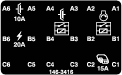
Check the Normal Engine Starting Chart
| System | ||||||
| Parking Brake | PTO | Motion Control Levers | Operator | Outcome | ||
| State of System | Engaged | Disengaged (Blades) | Both levers out (neutral lock) | In seat or out of the seat | Starter should crank | |
 |  |  |   |  |
||
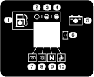
| System | ||||||
| Parking Brake | PTO Switch | Motion Control Levers | Operator | Outcome | ||
| State of System | Engaged | Up position, but blades disengaged* | Both levers out (neutral lock) | In seat or out of seat | Starter should crank | |
|  | | | |
||
*Note: The starter will crank with the PTO switch in the “ON” (pulled up) position; however, the system will disengage the PTO and a reset PTO error will occur. Engaging the PTO will require the operator to reset the PTO switch by turning it “OFF” (pushed down) and then turning it “ON”.
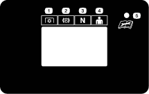
Check Engine Starting Circuit Chart
Note: In the Check Engine Starting Circuit Chart, the state of system item that is bold is being checked in each scenario.
| System | |||||
| Parking Brake | PTO (Blades) | Motion Control Levers | Operator | Outcome | |
| State of System | Engaged | Disengaged | Both levers moved in, or either right or left lever moved in | Operator in seat | Starter must not crank |
| |    | |  |
|
| Disengaged | Disengaged | Both levers out (neutral lock) | Operator in seat | Starter must not crank | |
 | | | | |
|
| System | ||||||
| Parking Brake | PTO (Switch) | Motion Control Levers | Operator | Outcome | ||
| State of System | Engaged | Up position | Both levers moved in, or either right or left lever moved in, or both levers out. | In seat or out of the seat | Starter must not crank | |
| | | | |
||
| Disengaged | Down position | Both levers out (neutral lock) | In seat or out of the seat | Starter must not crank | ||
|  | | | |
||
Check Shutdown Circuit Chart
Note: The state of system item(s) that is bold is being checked in each scenario.
| System | ||||||
| Engine | Parking Brake | PTO (Blades) | Motion Control Levers | Operator | Outcome | |
| State of System | Running idle (1/3 throttle or efficient mode) | Disengaged | Disengaged | Both levers moved out (neutral lock) or both levers moved in | Raise off of seat (but don’t get off) | Engine must begin shutdown within 1 second |
 | | | | |  |
|
| Check Shutdown Circuit Chart (continued) | ||||||
| System | ||||||
| Engine | Parking Brake | PTO (Blades) | Motion Control Levers | Operator | Outcome | |
| State of System | Running idle (1/3 throttle or efficient mode) | Disengaged | Engaged | Both levers moved in | Raise off of seat (but don’t get off) | Engine must begin shutdown within 1 second |
| |  | | | |
|
| Running idle (1/3 throttle or efficient mode) | Engaged | Disengaged | Both levers moved in, or either right or left lever moved in | Operator in seat | Engine must begin shutdown within 1 second | |
| | | | | |
|
| System | ||||||
| Engine | Parking Brake | PTO (Blades) | Motion Control Levers | Operator | Outcome | |
| State of System | Running idle (1/3 throttle or efficient mode) | Engaged | Engaged | Both levers moved out (neutral lock) | Raise off of seat (but don’t get off) | PTO must begin shutdown within 1 second; engine stays running. |
| | | | |  |
|
| System | ||||||
| Engine | Parking Brake | PTO (Blades) | Motion Control Levers | Operator | Outcome | |
| State of System | Running idle (1/3 throttle or efficient mode) | Disengaged | Engaged and Deck wings up | Both levers moved out (neutral lock) | Operator in seat | PTO must begin shutdown within 1 second; engine stays running. |
| |  | | | |
|
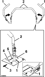
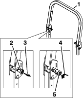
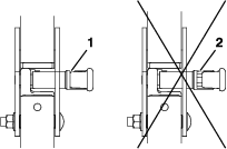
Check Rollover Protections Systems (Roll Bar) Knobs
| Maintenance Service Interval | Maintenance Procedure |
|---|---|
| Before each use or daily |
|
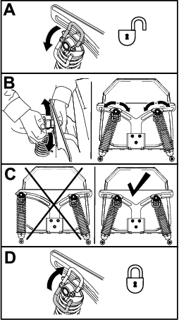
Check that both the mounting hardware and the knobs are in good working condition. Make sure the knobs are fully engaged with the ROPS in the raised position. The upper hoop of the roll bar may need to be pushed forward or pulled rearward to get both knobs fully engaged.
Check Wing Deck Bushings
| Maintenance Service Interval | Maintenance Procedure |
|---|---|
| Every 400 hours |
|
-
Position the machine on a flat surface.
-
Shut off the engine, wait for all moving parts to stop, and engage the parking brake.
-
Raise the center deck and fold the wings by pressing down at the rear of the deck lift rocker switch. Hold the switch down until both wings are completely folded.
-
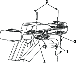
Push on the front corners of the deck near the lower bushings. If the there is more than 1/8 inch (3 mm) of movement, then the bushings need to be replaced.
Change Wing Deck Pivot Bushings
-
Position the mower on a flat surface.
-
Disengage the PTO and shut off the engine.
-
Remove and retain the clevis pins and hairpins from each wing deck storage location.
-
Be sure that all persons are clear of the deck wings. Press and hold the top of the deck control switch; the center deck will raise first and then the wings.
-
Secure each wing in the up position with the clevis pins and hairpins.
-
Loosen the bolts that secure the upper pivot pins to the deck but Do Not remove.
-
Remove and retain the clevis pins and hairpins from each wing deck. Remove the height adjustment pin from the deck lift plate on the right side of the center deck.
-
Lower the wing decks, but Do Not draw them into the operating position.
-
Remove and retain the left and right wing belt shield lynch pins, belt shield, and the wing deck belts.
-
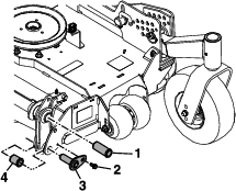
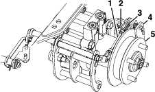
Remove and retain the locking cotter pins and the cylinder pins that attach to the rod end of the deck fold cylinders and to the wing decks.
Note: The wing decks must not be pulled into the operating position in order to remove the cylinder pins.
-
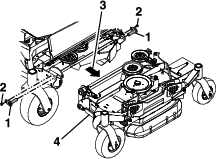
Remove and retain the bolts that secure the upper pivot pins to the deck and then remove the pivot pins.
-
Pull the wing deck outward to separate it from the center deck section.
-
Remove the flanged bushings from the upper pivot points and clean the bore.
-
Apply a thin bead of Loctite® 680 to the entire circumference of the rear edge of the new bushings.
-
Insert and gently tap the new bushings into the opening and properly seat them into place.
-
Place a block of wood under the inside edge of the center deck to make it easier to work on the lower pivot point bushings.
-
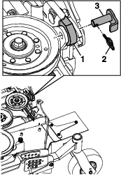
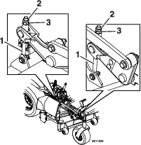
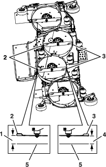
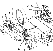
Remove and retain the lower pivot point bolts (reference Figure 45 and Figure 48).
-
Remove and discard the flanged bushing from the front and rear of the wing deck and clean the bore.
-
Apply a thin bead of Loctite® 680 to the entire circumference of the rear edge of the new bushings.
-
Insert and gently tap the new bushings into the opening and properly seat them into place.
-
Reinstall the lower deck pin assemblies and bolts into the lower deck pivot points and hand-tighten.
-
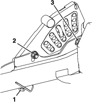
To aid in the ease of reinstalling the wing deck sections, carefully remove the exposed end of the spring that applies pressure to the rear of the wing deck cover.
-
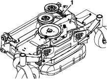
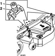
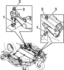
Push the left wing deck back to the center deck. Align and install the upper pivot deck pins in the front and rear of the deck and secure with the bolts that were removed previously (reference Figure 47).
-
Align the lift cylinder arm and reinstall the pin, making sure that the locking tab is aligned with the associated opening in the mount. Reinstall the locking cotter pin to secure.
-
Reattach the spring that was removed in Step 22 that applies pressure to the rear of the wing deck cover.
-
Reinstall the wing deck belts.
-
Reinstall the wing deck belt shields and secure with the lynch pins.
-
Raise the wings to the transport position and secure them in place with the clevis pins and hairpins.
-
Reinstall the height of cut pin.
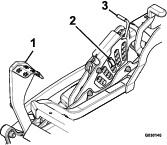
Check Seat Belt
| Maintenance Service Interval | Maintenance Procedure |
|---|---|
| Before each use or daily |
|
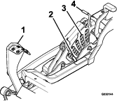
Visually inspect seat belt for wear, cuts, and proper operation of retractor and buckle. Replace before operating if damaged.
Check for Loose Hardware
| Maintenance Service Interval | Maintenance Procedure |
|---|---|
| Before each use or daily |
|
-
Stop engine, wait for all moving parts to stop, and remove key. Engage parking brake.
-
Visually inspect machine for any loose hardware or any other possible problem. Tighten hardware or correct the problem before operating.
Service Air Cleaner
| Maintenance Service Interval | Maintenance Procedure |
|---|---|
| Every 100 hours |
|
| Every 250 hours |
|
| Every 400 hours |
|
| Every 500 hours |
|
| Every 600 hours |
|
-
Stop engine, wait for all moving parts to stop, and remove key. Engage parking brake.
-
See the Engine Owner's Manual for maintenance instructions.
Check Air Filter Assembly (if equipped)
Important: To prevent engine damage, always operate the engine with both air filters and cover installed.
-
When checking or replacing the air filter element, make sure the air filter assembly is installed in the brackets.
-
Position the air cleaner cover so that the breather valve does not interfere with the throttle mechanism.
-
Secure the cover with latches.
Change Kohler, Briggs Non-EFI, and Kawasaki Engine Oil
| Maintenance Service Interval | Maintenance Procedure |
|---|---|
| After the first 5 hours |
|
| Every 100 hours |
|
-
Stop engine, wait for all moving parts to stop, and remove key. Engage parking brake.
-
Drain oil while engine is warm from operation.
-
Remove dip stick. The oil drain hose is located on right hand side of engine at the rear. Place pan under machine to catch oil. Remove plug from end of drain hose. Allow oil to drain.
-
Replace the oil filter every other oil change. Clean around oil filter and unscrew filter to remove. Before reinstalling new filter, apply a thin coating of Exmark 4–Cycle Premium Engine oil on the surface of the rubber seal. Turn filter clockwise until rubber seal contacts the filter adapter then tighten filter an additional 1/2 to 3/4 turn.
-
Clean around oil fill cover and remove cap. Fill to specified capacity and replace cap.
-
Use oil recommended in the Check Engine Oil Level section. Do Not overfill. Start the engine and check for leaks.
-
Wipe up any spilled oil from engine deck mounting surfaces.
Change Briggs EFI Engine Oil
| Maintenance Service Interval | Maintenance Procedure |
|---|---|
| Every 500 hours |
|
-
Stop engine, wait for all moving parts to stop, and remove key. Engage parking brake. Disconnect the spark plug wire and keep it away from the spark plug.
-
Drain oil while engine is warm from operation.
-
Remove dip stick from the oil tank.
-
Turn and remove the oil drain cap. Located at the bottom of the oil reservoir. Drain into approved container (no hose included).
-
Replace the oil filter every oil change. Open oil fill cover on top of oil reservoir. Remove the oil filter and dispose of it properly.
-
Clean around oil fill cover and install a new oil filter.
-
Make sure the machine is level. Use oil recommended in the Check Engine Oil Level section. Remove dip stick, and Slowly pour oil into the engine fill. Do Not overfill. Reinstall the dip stick back and close oil fill cover.
-
Remove dip stick and check the oil level. Correct oil level is at the top of the full indicator on the dip stick. Reinstall the dip stick and wipe up any spilled oil.
-
Reconnect the spark plug wires to the spark plug. Start the engine and check for leaks.
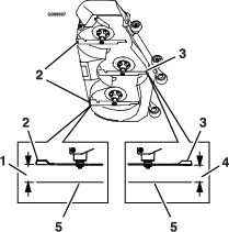
Check Deck Lift Oil Level
| Maintenance Service Interval | Maintenance Procedure |
|---|---|
| Every 50 hours |
|
-
Stop engine and wait for all moving parts to stop. Engage parking brake.
-
Wait until the machine cools before checking the deck lift oil.
-
Clean the area around the oil fill cap and remove cap.
-
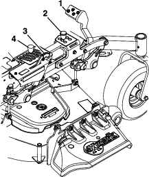
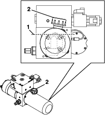
The oil level should be slightly above the internal gear pump in the tank (reference Figure 51). If needed, add Exmark Ruby Tran™ oil.
-
Replace hydraulic reservoir cap and tighten until snug. Do Not overtighten.
Check Hydraulic Oil Level
| Maintenance Service Interval | Maintenance Procedure |
|---|---|
| Every 50 hours |
|
-
Stop engine and wait for all moving parts to stop. Engage parking brake.
-
Wait until the machine cools before checking the hydraulic oil.
-
Adjust the seat to the most forward position to access the caps on the LH and RH hydro drives.
-
Clean the area around hydraulic reservoir cap and remove cap.
-
Wipe the dipstick clean and re-insert the cap back into the hydro. Lightly tighten the cap.
-
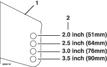
Remove the cap again and check the level of the oil on the dipstick. See Figure 52 for oil levels.
Note: The oil level on the dipstick will be incorrect if the oil is checked when the unit is hot.
-
If the dipstick oil level is at the “add” mark add Exmark Premium Hydro Oil.
-
Replace hydraulic reservoir cap and tighten until snug. Do Not overtighten.
Check Tire Pressures
| Maintenance Service Interval | Maintenance Procedure |
|---|---|
| Every 50 hours |
|
-
Stop engine, wait for all moving parts to stop, and remove key. Engage parking brake.
-
Check tire pressure in drive tires and pneumatic casters.
-
Inflate pneumatic casters to 13 psi (90 kPa).
Inflate drive tires:
-
All Models Except Wing Deck Models: 13 psi (90 kPa)
-
Wing Deck Models: 18 psi (124 kPa)
-
-
Semi-pneumatic caster tires Do Not need to be inflated.
Note: Do Not add any type of tire liner or foam fill material to the tires. Excessive loads created by foam filled tires may cause failures to the hydro drive system, frame, and other components. Foam filling tires will void the warranty.
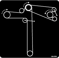
Check Condition Of Belts
| Maintenance Service Interval | Maintenance Procedure |
|---|---|
| Every 50 hours |
|
-
Stop engine, wait for all moving parts to stop, and remove key. Engage parking brake.
-
Remove left and right belt shields on deck and lift up floor pan to inspect deck drive belt.
-
Check under machine to inspect the pump drive belt.
Note: No adjustments are required for belt tension.
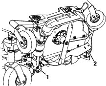
Lubricate Grease Fittings
| Maintenance Service Interval | Maintenance Procedure |
|---|---|
| Yearly |
|
Note: See chart for service intervals.
-
Stop engine, wait for all moving parts to stop, and remove key. Engage parking brake.
-
Lubricate fittings with one to two pumps of NLGI grade #2 multi-purpose gun grease.
Refer to the following chart for fitting locations and lubrication schedule.
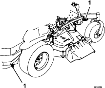
All Models Except Wing Deck Models
Lubrication Chart Fitting Locations Initial Pumps Number of Places Service Interval 1. Deck and Pump Idler Pivots 1 2 Yearly 2. Front Caster Pivots *0 2 *Yearly 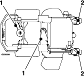
* See step 3 for special lubrication instructions on the front caster pivots.
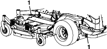
Wing Deck Models
Lubrication Chart Fitting Locations Initial Pumps Number of Places Service Interval 1. Deck and Pump Idler Pivots 1 4 Yearly 2. Caster Pivots *0 5 *Yearly 3. Front Caster Wheel Bearings *0 4 *Yearly 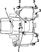
* See step 3 for special lubrication instructions on the caster pivots.
-
Lubricate caster pivots once a year. Remove hex plug and cap. Thread grease zerk in hole and pump with grease until it oozes out around top bearing. Remove grease zerk and thread plug back in. Place cap back on.
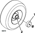
Lubricate Caster Wheel Hubs
-
Stop engine, wait for all moving parts to stop, and remove key. Engage parking brake.
-
Remove caster wheel from caster forks.
-
Remove seal guards from the wheel hub.
-
Remove one of the spacer nuts from the axle assembly in the caster wheel. Note that thread locking adhesive has been applied to lock the spacer nuts to the axle. Remove the axle (with the other spacer nut still assembled to it) from the wheel assembly.
-
Pry out seals, and inspect bearings for wear or damage and replace if necessary.
-
Pack the bearings with a NLGI grade #1 multi-purpose grease.
-
Insert one bearing, one new seal into the wheel.
Note: Seals (Exmark P/N 103-0063) must be replaced.
-
If the axle assembly has had both spacer nuts removed (or broken loose), apply a thread locking adhesive to one spacer nut and thread onto the axle with the wrench flats facing outward. Do Not thread spacer nut all of the way onto the end of the axle. Leave approximately 1/8 inch (3 mm) from the outer surface of the spacer nut to the end of the axle inside the nut.
-
Insert the assembled nut and axle into the wheel on the side of the wheel with the new seal and bearing.
-
With the open end of the wheel facing up, fill the area inside the wheel around the axle full of NLGI grade #1 multi-purpose grease.
-
Insert the second bearing and new seal into the wheel.
-
Apply a thread locking adhesive to the 2nd spacer nut and thread onto the axle with the wrench flats facing outward.
-
Torque the nut to 75-80 in-lb (8-9 N-m), loosen, then re-torque to 20-25 in-lb (2-3 N-m). Make sure axle does not extend beyond either nut.
-
Reinstall the seal guards over the wheel hub and insert wheel into caster fork. Reinstall caster bolt and tighten nut fully.
Important: To prevent seal and bearing damage, check the bearing adjustment often. Spin the caster tire. The tire should not spin freely (more than 1 or 2 revolutions) or have any side play. If the wheel spins freely, adjust torque on spacer nut until there is a slight amount of drag. Reapply thread locking adhesive.
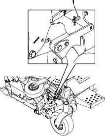
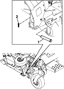
Lubricate Deck Lift Pivot
| Maintenance Service Interval | Maintenance Procedure |
|---|---|
| Every 100 hours |
|
-
Stop engine, wait for all moving parts to stop, and remove key. Engage parking brake.
-
Lubricate deck lift pivot with a spray type lubricant or light oil.
Check Spark Plugs
| Maintenance Service Interval | Maintenance Procedure |
|---|---|
| Every 200 hours |
|
Remove spark plugs, check condition and reset gaps, or replace with new plugs. See Engine Owner's Manual.
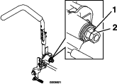
Change Fuel Filter
A fuel filter is installed between the fuel tank and the engine. Replace when necessary.
Note: It is important to reinstall the fuel line hoses and secure with plastic ties the same as they were originally installed at the factory to keep the fuel line away from components that could cause fuel line damage.
Change Hydraulic System Filter and Fluid
| Maintenance Service Interval | Maintenance Procedure |
|---|---|
| After the first 250 hours |
|
| Every 500 hours |
|
Note: Only use Exmark Hydro Filter–Part No. 116-0164 for summer or winter.
-
Stop engine, wait for all moving parts to stop, and remove key. Engage parking brake.
-
Raise the rear of machine up and support with jack stands (or equivalent support) just high enough to allow drive wheels to turn freely.
-
Remove the pump drive belt.
-
Place a catch pan under the hydro.
-
Carefully clean area around the filters. It is important that no dirt or contamination enter the hydraulic system.
-
Using a socket, unscrew filters to remove and allow oil to drain.
-
Before installing the new filters, apply a thin coat of Exmark Premium Hydro Oil on the surface of the two rubber seals.
-
Install the new filters and torque to 14 ft-lb (19 N-m).
-
Fill the hydraulic system as stated in Check Hydraulic Oil Level section.
Exmark Premium Hydro Oil is recommended. Refer to the chart for an acceptable alternative:
Hydro Oil Service Interval Exmark Premium Hydro Oil (Preferred) After first 250 hours*Every 500 hours thereafter Mobil 1 15W50 After first 250 hours *Every 250 hours thereafter *May need more often under severe conditions.
-
Remove the catch pan and properly dispose of hydro oil and filter according to local codes.
-
Re-install the pump drive belt.
-
Start engine and move throttle control ahead to full throttle position. Move the speed control levers to the full speed and run for one minute. Shut down the machine, allow the hydros to cool and recheck oil level.
-
Remove the jack stands.
Note: Do Not change the hydraulic system oil (except for what can be drained when changing filter), unless it is felt the oil has been contaminated or been extremely hot.Changing oil unnecessarily could damage hydraulic system by introducing contaminants into the system.
Change Deck Lift Power Unit Fluid–Wing Deck Model Only
| Maintenance Service Interval | Maintenance Procedure |
|---|---|
| Yearly or before storage |
|
-
Position the machine and cutting unit on a level surface.
-
Lower the mower deck to the 1 inch (2.5 cm) height of cut.
-
Disengage the PTO, move the motion control levers to the neutral-lock position, and engage the parking brake.
-
Shut off the engine, remove the key, and wait for all moving parts to stop before leaving the operating position.
-
Unlatch the hood and lift it up to access the oil fill. Clean around the fill cap and remove cap.
-
Extract oil through the fill port using a vacuum devise or remove the power unit from the deck and pour the oil out.
-
Reinstall the power unit if it was removed to drain.
-
Add enough Exmark Ruby Tran™ oil, approximately 24 oz (710 ml) and replace cap.
Important: Do Not overfill the power unit; overfilling the power unit may damage it.
-
Check the fluid level.
Wheel Hub–Slotted Nut Torque Specification
| Maintenance Service Interval | Maintenance Procedure |
|---|---|
| After the first 100 hours |
|
| Every 500 hours |
|
-
All Except Wing Deck Models:
Torque the slotted nut to 211-260 ft-lb (286-352 N-m).
-
Wing Deck Models:
Torque the slotted nut to 310-340 ft-lb (420-461 N-m).
Note: Do Not use anti-seize on wheel hub.
Check Spark Arrester
| Maintenance Service Interval | Maintenance Procedure |
|---|---|
| Every 50 hours |
|
Warning
Hot exhaust system components may ignite gasoline vapors even after the engine is stopped. Hot particles exhausted during engine operation may ignite flammable materials. Fire may result in personal injury or property damage.
Do Not refuel or run engine unless spark arrester is installed.
-
Stop engine, wait for all moving parts to stop, and remove key. Engage parking brake.
-
Wait for muffler to cool.
-
If any breaks in the screen or welds are observed, replace arrester.
-
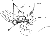
If plugging of the screen is observed, remove arrester and shake loose particles out of the arrester and clean screen with a wire brush (soak in solvent if necessary). Reinstall arrester on exhaust outlet.
Thread Locking Adhesives
Thread locking adhesives such as “Loctite 242” or “Fel-Pro, Pro-Lock Nut Type” are used on the following fasteners:
-
ROPS spring pin housing.
-
Hydro pump control arm, linkage bolt, and attachment bolt.
-
Hydro cooling fan screw.
-
Hydro park brake anchor mounting bolt
-
Sheave and clutch retaining bolt in the end of engine crankshaft.
Thread locking adhesives are required for some hardware on engines — see the Engine manual.
Mobil HTS Grease (Or Food-Grade Anti-seize)
Mobil HTS grease (or food-grade anti-seize) is used in the following location:
Between the cutter housing spindles and bearings. On 96 inch decks, also grease the anti-scalp roller bolts.
Copper-Based Anti-seize
Copper-based anti-seize is used in the following location:
On threads of Blade Bolts. See Check Mower Blades section.
Dielectric Grease
Dielectric grease is used on all blade type electrical connections to prevent corrosion and loss of contact. Dielectric grease should not be applied to sealed connectors.
Adjustments
Note: Disengage PTO, shut off engine, wait for all moving parts to stop, engage parking brake, and remove key before servicing, cleaning, or making any adjustments to the machine.
Deck Leveling–
-
Position the mower on a flat surface.
-
Stop engine, wait for all moving parts to stop, and remove key. Engage parking brake.
-
Check the tire pressure in drive tires and pneumatic front caster tires (if equipped). Proper inflation pressure for tires is 13 psi (90 kPa). Adjust if necessary.
-
Position the transport lock in the latching position.
-
Push the foot pedal all the way forward and the deck will latch at the 5 1/2 inch (14 cm) transport position (Figure 54).
-
Insert the height adjustment pin into the 3 inch (7.6 cm) cutting height location.
-
Release the transport lock and allow the deck to lower to the cutting height.
-
Raise the discharge deflector (side discharge units only).
-
Measure from the level surface to the front tip of the center blade. The measurement should read 3 inches (7.6 cm).
Note: In most conditions, the back tips on the side blades should be adjusted:Side Discharge Units: 1/4 inch (6.4 mm) higher than the front.Rear Discharge Units: to be level with the front.
-
Adjust the height — to increase, turn the adjuster screw clockwise; to decrease, turn counterclockwise.
-
X-Series:
Loosen the jam nuts on the top of each deck adjuster. Fine tune the adjuster on the front deck lift assembly by turning it to get 3 inch (7.6 cm) height (see Figure 56).
-
S and E-Series:
Fine tune the front deck lift assembly by turning the adjuster screw until it reaches the 3 inch (7.6 cm) height (see Figure 57).
-
-
Measure the back tip height. Fine tune rear adjusters as required; the single point adjustment can be utilized to gain more adjustment.
-
Side Discharge Units: The back tips of the side blades should measure 3 1/4 inches (8.3 cm).
-
Rear Discharge Units: The back tips of the side blades should measure 3 inches (7.6 cm).
-
-
Re-measure until all four sides are the correct height. Tighten all the nuts on the deck lift arm assemblies.
-
Lower discharge deflector (side discharge units only).
-
If the four deck adjusters do not have enough adjustment to achieve accurate cut height with the desired rake, the single point adjustment can be utilized to gain more adjustment (see Figure 58).
-
To adjust the single point system, first loosen the front and rear height-of-cut plate mounting bolts.
Note: On Rear Discharge Units: The mower deck is attached in the front holes at the factory (see Figure 59). If needed, use the back holes for further adjustment when leveling the mower deck.
-
If the deck is too low, tighten the single point adjustment bolt by rotating it clockwise. If the deck is too high, loosen the single point adjustment bolt by rotating it counterclockwise.
Note: Loosen or tighten the single point adjustment bolt enough to move the height-of-cut plate mounting bolts at least 1/3 the length of the available travel in their slots. This will regain some up and down adjustment on each of the four deck links.
-
Re-tighten front and rear height-of-cut plate mounting bolts.
Important: Torque the front and rear height-of-cut plate mounting bolts to 27-33 ft-lb (37-45 N-m).
-
Repeat steps 9 through 13.
Deck Leveling–
Leveling the Center and Wing Decks
-
Position the machine on a flat surface.
-
Shut off the engine, wait for all moving parts to stop, remove the key, and engage the parking brake.
-
Check the tire pressure in drive tires. Proper inflation pressure for tires is 18 psi (124 kPa). Adjust if necessary.
-
Raise the center deck and fold the wings by pressing down at the rear of the deck lift rocker switch. Hold the switch down until both wings are completely folded.
-
Insert the center height adjustment pin into the 4 inches (102 mm) cutting height location.
-
Unlock the left and right wing deck cam locks.
-
Remove and retain the wing deck height of cut lynch pins.
-
Insert the height adjustment pin into the 4 inch (102 mm) cutting height location and reinstall the lynch pins.
-
Lock the left and right wing deck cam locks.
-
Start engine. Brake must be engaged and motion control levers out to start engine. Operator does not have to be in the seat. Be sure that all persons are clear of the deck wings. Press and hold the front of the deck control switch until the center deck lowers and both wings are completely unfolded to the cutting height.
-
Stop engine, wait for all moving parts to stop, engage the parking brake and remove the key.
-
Measure from the level surface to the front tip of the LH and RH center deck blades. The measurement should read 4 inches (102 mm).
Adjusting the Center Deck
-
Adjust the height — to increase, turn the adjuster screw clockwise; to decrease, turn counterclockwise.
Loosen the jam nuts on the top of each deck adjuster. Fine tune the adjuster on the front deck lift assembly by turning it to get the correct height for the center deck left and right front blade tips (see Figure 62).
-
Measure the back tip height. Fine tune rear adjusters as required; the single point adjustment can be utilized to gain more adjustment.
-
Re-measure until all four sides are the correct height. Tighten all the jam nuts on the deck lift arm assemblies.
-
If the four deck adjusters do not have enough adjustment to achieve accurate cut height with the desired rake, the single point adjustment can be utilized to gain more adjustment
-
To adjust the single point system, first loosen the front and rear height of cut plate mounting bolts. Fine tune the rear adjusters as required; the single point adjustment can be utilized to gain more adjustment.
-
If the deck is too low, tighten the single point adjustment bolt by rotating it clockwise. If the deck is too high, loosen the single point adjustment bolt by rotating it counterclockwise. Loosen the front and rear height of cut plate mounting bolts. Fine tune the rear adjusters as required; the single point adjustment can be utilized to gain more adjustment.
Note: Loosen or tighten the single point adjustment bolt enough to move the height of cut plate mounting bolts at least 1/3 the length of the available travel in their slots. This will regain some up and down adjustment on each of the four deck links.
-
Re-tighten front and rear height of cut plate mounting bolts.
Important: Torque the front and rear height of cut plate mounting bolts to 27-33 ft-lb (37-45 N-m).
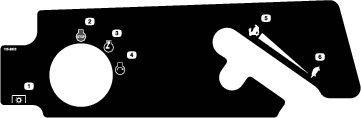
Adjusting the Wing Decks
-
Measure from the level surface to the front tip of the LH wing deck blade. The measurement should read 4 inches (102 mm).
-
Measure from the level surface to the front tip of the RH wing deck blade. The measurement should read 4 inches (102 mm).
Note: As with the center deck, in most conditions the back tips on the wing blades should be adjusted 1/4 inch (6.4 mm) higher than the front.
-
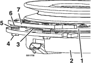
The left and right wing decks have blade height adjustments with front and rear adjust points. To adjust the wing blade height, first loosen the front and rear height of cut hanger mounting nuts. There are four locations — two on each side of the channel (see Figure 64).
-
If the deck is too low, tighten the front height adjustment bolt (item 5, Figure 64) by rotating the bottom nut clockwise.
-
If the deck is too high, loosen the front height adjustment bolt (item 5, Figure 64) by rotating the bottom nut counterclockwise. Fine tuned the rear adjusters as required.
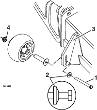
Adjust the rear wheel height (item 2, Figure 64) so that the rear wheel lightly touches the ground with minimal pressure.
-
-
Measure the back of the wing blades. If either has less than 1/16 inch (1.5 mm) rake, raise the back of the deck by tightening the LH and RH rear adjustments (item 3, Figure 64) until all four blades have a minimum of 1/16 inch rake (1.5 mm). Readjust the wing rear wheels so they lightly touch the ground with minimal pressure. Tighten all four rear hanger mount points (item 1, Figure 64).
-
Retighten the front and rear height of cut hanger jam nuts.
Pump Drive Belt Tension
Self-tensioning - No adjustment necessary.
Deck Belt Tension
Self-tensioning - No adjustment necessary.
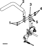
Adjusting the Parking Brake
| Maintenance Service Interval | Maintenance Procedure |
|---|---|
| After the first 100 hours |
|
| Every 500 hours |
|
Check to make sure brake is adjusted properly. This procedure must be followed after the first 100 hours or when a brake component has been removed or replaced.
-
Drive the machine onto a level surface.
-
Disengage the blade control switch (PTO), move the motion control levers to the neutral locked position and engage the parking brake (lever is in the “up” position).
-
Stop the engine, wait for all moving parts to stop, and remove the key.
-
Raise the back of the machine up and support the machine with jack stands.
-
Remove the rear tires from the machine.
-
Remove any debris from the brake area.
-
Rotate the drive wheel release handle to the “released” position. Refer to the Drive Wheel Release Valves section in Operation.
-
Disengage the park brake.
-
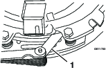
Remove the spring clevis pin from the rear linkage and caliper.
-
Loosen the jam nut on the rear linkage.
-
Push the caliper lever forward with finger pressure until the brake pad contacts the hub rotor.
-
Adjust the rear linkage until the spring clevis pin can be inserted in the hole in the caliper lever.
Note: To lengthen the linkage, rotate the clevis one turn outward.
-
Tighten the jam nut on the rear linkage.
-
Wheel hub should move freely between the caliper.
-
Repeat steps 9 through 14 for the brake on the right side.
-
Rotate the drive wheel release handle to the “operating” position. Refer to the Drive Wheel Release Valves section in Operation.
-
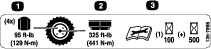
Install the rear tires and torque lug nuts to 95 ft-lb (129 N-m).
-
Remove jack stands.
Electric Clutch Adjustment
No adjustment necessary. However, when the clutch brake has worn to the point where the clutch no longer engages consistently, the shim can be removed to extend the clutch life (not applicable for Lazer Z E-Series with 48 inch decks).
Removing the Shim:
-
Stop engine, wait for all moving parts to stop, and remove key. Engage parking brake. Allow the machine to cool completely before starting these instructions.
-
Using a pneumatic line, blow out any debris from under the brake pole and around the brake spacers.
-
Check the condition of the wire harness leads, connectors, and terminals. Clean or repair as necessary.
-
Verify that 12V is present at the clutch connector when the PTO switch is engaged.
-
Measure the gap between the rotor and armature. If the gap is greater than .04 inch (1 mm), proceed with the following steps:
-
Loosen both brake mounting bolts one-half to one full turn (see Figure 67).
Note: Do Not remove the brake pole from the field shell/armature. The brake pole has worn to match the armature and needs to continue to match after the shim is removed to ensure proper brake torque.
-
Using needle nose pliers, or by hand, take hold of the tab and remove the shim (Do Not discard the shim until proper clutch function has been confirmed).
-
Using a pneumatic line, blow out any debris from under the brake pole and around the brake spacers.
-
Re-torque each bolt (M6 x 1) to 10 ft-lb (13 N-m) +/-0.5 ft-lb (0.7 N-m).
-
Using a 0.010 inch thick feeler gauge, verify that a gap is present between the rotor and armature face on both sides of the brake pole as shown. (Due to the way the rotor and armature faces wear (peaks and valleys) it is sometimes difficult to measure the true gap.)
-
If the gap is less than 0.010 inch, then reinstall the shim and reference the Troubleshooting section.
-
If the gap is sufficient, proceed to the safety check in step 6.
-
-
Perform the following safety check:
-
Sit on the seat and start the engine.
-
Make sure the blades Do Not engage with the PTO switch “off” and the clutch disengaged.
If the clutch does not disengage, reinstall the shim and reference the Troubleshooting section.
-
Engage and disengage the PTO switch ten consecutive times to ensure the clutch is functioning properly. If the clutch does not engage properly, reference the Troubleshooting section.
-
-
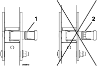
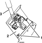
Motion Control Linkage Adjustment
Located on either side of the fuel tank, below the seat are the pump control linkages. Rotating the pump linkage with a 1/2 inch wrench allows fine tuning adjustments so that the machine does not move in neutral. Any adjustments should be made for neutral positioning only.
-
Prior to starting the engine, push the deck lift pedal and remove the height of cut pin. Lower deck to the ground.
-
Raise the rear of machine up and support with jack stands (or equivalent support) just high enough to allow drive wheels to turn freely.
-
Remove the electrical connection from the seat safety switch, located under the bottom cushion of the seat. The switch is a part of the seat assembly.
-
Temporarily install a jumper wire across the terminals in the connector of the main wiring harness.
-
Start engine. Brake must be engaged and motion control levers out to start engine. Operator does not have to be in the seat because of the jumper wire being used. Run engine at full throttle and release brake.
-
Run the unit at least 5 minutes with the drive levers at full forward speed to bring hydraulic oil up to operating temperature.
Note: The motion control lever needs to be in neutral while making any necessary adjustments.
-
Bring the motion control levers into the neutral position. Adjust pump control rod lengths by rotating the double nuts on the rod in the appropriate direction until the wheels slightly creep in reverse (Figure 70). Move the motion control levers to the reverse position and while applying slight pressure to the lever allow the reverse indicator springs to bring the levers back to neutral. The wheels must stop turning or slightly creep in reverse.
-
Shut off unit. Remove jumper wire from wire harness and plug connector into seat switch.
-
Remove the jack stands.
-
Raise the deck and re-install the height of cut pin.
-
Check that the machine does not creep in neutral with the park brakes disengaged.
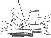
Motion Control Damper Adjustment
The top damper mounting bolt can be adjusted to obtain a more desired motion control lever resistance. See Figure 71 for mounting options.
Motion Control Neutral Lock Pivot Adjustment
The flanged nut can be adjusted to obtain a more desired motion control lever resistance (Figure 72).
-
Loosen the jam nut.
-
Tighten or loosen the flanged nut to the desired feel.
For more resistance, tighten the flanged nut.
For less resistance, loosen the flanged nut
-
Tighten jam nut.
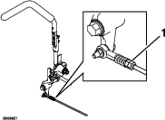
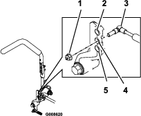
Motion Control Handle Adjustment
Adjusting the height:
The motion control levers can be adjusted higher or lower for maximum operator comfort.
-
Remove the two bolts holding the control lever to the control arm shaft (Figure 73).
-
Move the control lever to the next set of holes. Secure the lever with the two bolts.
-
Repeat the adjustment for the opposite control lever.
Adjusting the Tilt
The motion control levers can be tilted fore or aft for maximum operator comfort.
-
Loosen the upper bolt holding the control lever to the control arm shaft.
-
Loosen the lower bolt just enough to pivot the control lever fore or aft Figure 73. Tighten both bolts to secure the control in the new position.
-
Repeat the adjustment for the opposite control lever.
Motion Control Full Forward Tracking Adjustment
If the machine travels or pulls to one side when the motion control levers are in the full forward position, adjust the cover plates.
-
Loosen the screws on a cover plate (see Figure 74).
-
Slide the cover plate backward or forward to adjust the travel of the lever and tighten the screws.
-
Drive the machine and check the full forward tracking.
-
Repeat steps 1 through 3 until desired tracking is obtained.
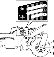
Caster Pivot and Gauge Wheel Pivot Bearings Pre-Load Adjustment
Remove dust cap from caster and tighten nyloc nut until washers are flat and back off 1/4 of a turn to properly set the pre-load on the bearings. If disassembled, make sure the spring disc washers are reinstalled as shown in Figure 75.
Cleaning
Cleaning and Storing Safety
-
Park machine on level ground, disengage drives, set parking brake, stop engine, and remove key. Wait for all moving parts to stop before leaving the operator’s position. Allow the machine to cool before servicing, adjusting, fueling, cleaning, or storing.
-
Clean grass and debris from the cutting unit, muffler, drives, grass catcher, and engine compartment to prevent fires.
-
Allow the machine to cool before storing the machine in any enclosure. Do Not store the machine or fuel container, or refuel, where there is an open flame, spark, or pilot light such as on a water heater or other appliance.
Clean Debris From Machine
| Maintenance Service Interval | Maintenance Procedure |
|---|---|
| Before each use or daily |
|
-
Stop engine, wait for all moving parts to stop, and remove key. Engage parking brake.
-
Clean off any oil, debris, or grass build-up on the machine and cutting deck, especially under deck belt shields, around the fuel tank, around engine and exhaust area.
Important: You can wash the machine with mild detergent and water. Do not pressure wash the machine. Avoid excessive use of water, especially near the control panel, under the seat, around the engine, hydraulic pumps, and motors.
Clean Engine and Exhaust System Area
| Maintenance Service Interval | Maintenance Procedure |
|---|---|
| Before each use or daily |
|
Caution
Excessive debris around engine cooling air intake and exhaust system area can cause engine, exhaust area, and hydraulic system to overheat which can create a fire hazard.
Clean all debris from engine and exhaust system area.
-
Stop engine, wait for all moving parts to stop, and remove key. Engage parking brake.
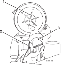
-
Clean all debris from rotating engine air intake screen, around engine shrouding, and exhaust system area.
-
Wipe up any excessive grease or oil around the engine and exhaust system area.
Remove Engine Shrouds and Clean Cooling Fins
| Maintenance Service Interval | Maintenance Procedure |
|---|---|
| Every 100 hours |
|
-
Stop engine, wait for all moving parts to stop, and remove key. Engage parking brake.
-
Remove cooling shrouds from engine and clean cooling fins. Also clean dust, dirt and oil from external surfaces of engine which can cause inadequate cooling.
-
Make sure cooling shrouds are reinstalled. Operating the engine without cooling shrouds will cause engine damage due to overheating.
Clean Hydro Fan Cooling Guards, Hydro Cooling Fins, and Fan
| Maintenance Service Interval | Maintenance Procedure |
|---|---|
| Before each use or daily |
|
Removing debris from the hydro fan cooling guards, hydro cooling fins, and fan will allow the hydro system to run cooler and improve the life of the hydro system.
-
Stop engine, wait for all moving parts to stop, and remove key. Engage parking brake.
-
Slide seat all the way back, then lift the seat to access the LH and RH hydro drive area.
-
Remove accumulated debris from the hydro fan cooling guards, hydro cooling fins, and fan.
Clean Grass Build-Up Under Deck
| Maintenance Service Interval | Maintenance Procedure |
|---|---|
| Before each use or daily |
|
-
Stop engine, wait for all moving parts to stop, and remove key. Engage parking brake.
-
Raise deck to the transport (5 1/2 inch (14 cm) cutting height) position. Lift the front of unit and support unit using jack stands or equivalent support.
-
Clean out any grass build-up from underside of deck and in discharge deflector.
Cleaning the Suspension System
Note: Do not clean the shock assemblies with pressurized water.

Waste Disposal
Motor Oil Disposal
Engine oil and hydraulic oil are both pollutants to the environment. Dispose of used oil at a certified recycling center or according to your state and local regulations.
Battery Disposal
Danger
Battery electrolyte contains sulfuric acid, which is poisonous and can cause severe burns. Swallowing electrolyte can be fatal or if it touches skin can cause severe burns.
-
Wear safety glasses to shield eyes, and rubber gloves to protect skin and clothing when handling electrolyte.
-
Do Not swallow electrolyte.
-
In the event of an accident, flush with water and call a doctor immediately.
Federal law states that batteries should not be placed in the garbage. Management and disposal practices must be within relevant federal, state, or local laws.
If a battery is being replaced or if the unit containing the battery is no longer operating and is being scrapped, take the battery to a local certified recycling center. If no local recycling is available return the battery to any certified battery reseller.