Introduction
Refer to your machine Operator’s Manual for more information.
Setup
Converting the Data
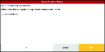
This topic explains how to convert Version 4.XX.XX legacy data using the Version 5.02.24.28 or newer Inventory Manager.
-
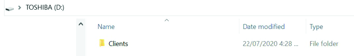
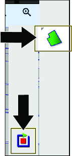
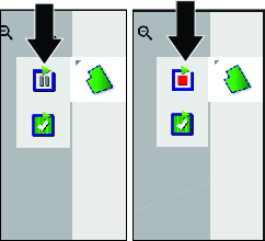
Place the 4.xx.xx legacy data you wish to convert into a folder labeled CLIENTS onto the root directory of a formatted USB.
-
Insert the USB into the console
-
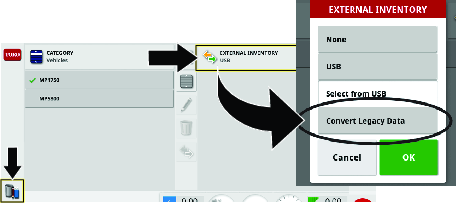
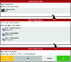
Select the Inventory Manager and select External Inventory.
-
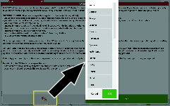
Select Convert Legacy Data from the drop-down menu.
-
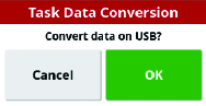
Once the console has recognized the legacy data on the USB, select OK for the data to be converted.
-
Transfer the data from the USB to the console.
-
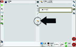
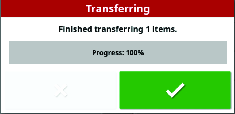
Once the client data has been successfully converted, you will see the green check mark window.
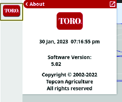
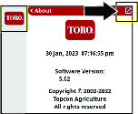
Verifying the Software Version
Contact Toro GeoLink Support for software updates.
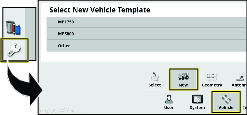
Adding a Vehicle
-
Go to the SETUP menu.
-
Press VEHICLE then press NEW and select the vehicle you are using..
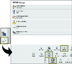
Updating the NTRIP Settings
-
Fill out the Geolink Activation Form.
https://www.toro.com/en/customer-support/contact/geolink-signup
An auto-reply is sent to confirm the form has been submitted.
Another e-mail is sent out with the NTRIP information upon activation of the RTK subscription.
-
Navigate to NTRIP SETUP in the SETTINGS menu.
-
Enter the information provided to you in the e-mail.
Selecting the Units of Measure
-
Press the SETUP icon on the main screen.
-
Press the USER icon.
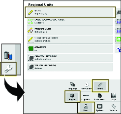
-
Press the REGION icon.
-
Press the UNITS icon.
-
As needed, select the desired units and application rate, and press the confirm icon.
Creating a New Product and Application Rate
-
Press the SPRAYER CONTROLLER icon and press the full screen icon.
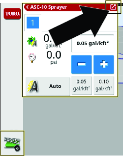
-
Press the product icon.
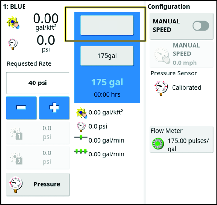
-
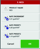
In the product configuration window, press the PRODUCT NAME icon.
-
Select NEW PRODUCT.
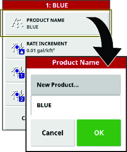
-
Press CUSTOM PRODUCT to name the product.
Note: Create a custom product for each nozzle color (size).
-
Go through the New Product wizard to set the product rate increment and preset values.
-
Press the confirmation box to verify the settings are correct.
Verifying the Cellular Status
-
Press the SYSTEM MENU icon and press the full screen icon.
-
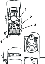
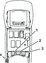
Scroll down to CL-55 to display the signal strength information and verify that the modem signal strength is between -60 dBm and -99 dBm.
Note: If the modem signal is equal to or less than -100 dBm, Contact your authorized Toro distributor or Toro GeoLink Support.
Clearing the NVRAM
Changing the Setup Screen for Dealer Access
Note: You must clear the nonvolatile RAM at the customer location.
-
Contact Toro support to request the dealer access level password.
-
Press the SETUP icon on the main screen.
-
In the setup screen, press the USER icon and the ACCESS LEVEL icon.
Note: Switch to standard mode if the machine is in easy mode.
-
Press the PASSWORD icon
-
Use the on-screen keyboard to enter the password and press the confirm icon
Note: The user access level screen displays the DEALER icon.
Erasing the Nonvolatile RAM
-
Turn the machine on.
-
In the setup screen, press the SYSTEM icon, GPS icon, and ADVANCED CONFIGURATION icon
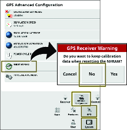
-
In the GPS Advanced Configuration screen, press the RESET NVRAM icon
-
In the GPS receive warning dialog box, press the NO icon
Note: The receiver disconnected warning displays briefly.
-
Wait 2 minutes for the satellite receiver and modem startup.
-
Press the CLOSE icon.
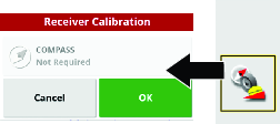
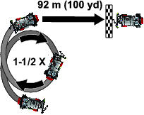
Calibrate the Compass
-
Press the RECEIVER CALIBRATION icon.
-
Press the COMPASS icon.
-
Drive the machine 1–1/2 revolutions in a circle that is at least 6 m (20 ft) diameter.
-
Press the next icon.
-
Drive straight for 92 m (100 yd).
-
Check the display for the compass calibration confirmation message.
Checking the Spray System
Note: The self-test feature simulates machine ground speed so that you can test the system without moving. This feature clears itself when the speed sensor detects that the vehicle is in motion. The self-test feature of the GeoLink system serves the similar function as the test speed feature of the Multi Pro 1750 and Multi Pro 5800 machines.
-
Engage the parking brake.
-
Add 200 L (50 US gallon) of water into the spray tank; refer to the Operator’s Manual for your machine.
-
Start the engine and set the engine speed to fast.
-
On the display, press the SPRAY RATE CONTROLLER icon.
-
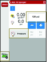
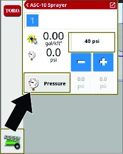
In the spray rate controller dialog box, select PRESSURE mode.
-
Adjust the spray system pressure to 8.27 bar (120 psi).
-
On the machine, turn the pump and master section switch to the ON position.
-
On the display, turn the MASTER SWITCH icon to ON (green)
 .
. -
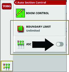
On the display, press the ASC icon and turn the ASC OFF.
-
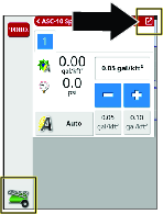
Press the sprayer-controller icon.
-
Press the full screen icon in the sprayer controller menu.
-
Press the configuration icon in the sprayer controller submenu to display the configuration menu.
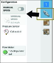
-
Press the MANUAL SPEED icon.
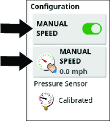
-
Enter the simulated speed.
-
Press the full screen icon to return sprayer controller menu.
-
Enter the desired application rate by using the pre-sets, increase or decrease icons, or by selecting the current-target application rate icon.
-
Check all sprayer fittings and components for leaks.
Note: If you find any leaks, shut off the engine and repair the fitting or component.
Balancing the Agitation Bypass Valve
Checking System and Agitation Bypass Pressure
-
Engage the parking brake, start the engine, set the throttle to the mid range.
Note: Allow the engine and hydraulic system to warm for 10 minutes.
-
Ensure that the master section switch to the OFF position
 .
. -
Set the spray-pump switch and the tank agitation switch to the ON position.
-
Set the left, center, and right section switches to the ON position.
-
Set the engine speed to fast.
-
On the display, press the SPRAY RATE CONTROLLER icon.
-
In the spray rate controller dialog box, press the RATE CONTROL MODE icon until PRESSURE mode displays.
-
Press the decrement icon (-) or increment icon (+) to adjust the spray system pressure to 6.9 bar (100 psi).

-
On the machine, set the tank agitation switch to the OFF position.
-
Observe the spray system pressure. If the spray system pressure is 6.9 bar (100 psi), the agitation valve is correctly adjusted.
-
If the spray system pressure changed, adjust the agitation bypass valve; refer to your Operator’s Manual.
Calibrating the Flow Meter
Preparing for the Calibration
Customer provided equipment:
-
A graduated catch container (graduated in 0.01 ml (1/2 fl. oz) increments is preferred)
-
A stopwatch capable of measuring ± 1/10 second.
-
Ensure that the sprayer tank is clean.
-
Fill the sprayer tank with at least 150 gallons of fresh water.
-
Ensure that the nozzles that you intend to test are in the active spray (down) position.
-
Engage the parking brake and start the engine.
Note: Allow the engine and hydraulic system to warm for 10 minutes.
Performing the Pretest Priming
-
On the command console, press the SPRAY RATE CONTROLLER icon.
-
Set the rate controller to PRESSURE MODE.
-
On the machine, set the sprayer pump switch to the ON position; refer to Operating the Spray System of the Machine.
-
Set all the 3 spray section switches to the ON position.
-
Set the throttle to the FAST position.
-
On the display, press the MASTER SWITCH icon
. -
On the machine, set the master section switch to the ON position.
-
Set the pressure to 2.75 bar (40 psi).
-
On the machine, set the master section switch to the OFF position.
Running the Catch Test and Entering the Information
-
On the machine, set the throttle to the FAST position.
Allow the spray pressure to stabilize.
-
Ensure that the 3 spray section switches are in the ON position.
-
In the control console, ensure that the MASTER SWITCH icon indicates green (system ready)
. -
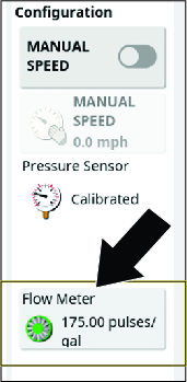
Press the FLOW METER icon.
Note: The auto flow calibration wizard displays.
Performing the 15-Second Catch Test
-
In step 1 of 4 of the auto flow calibration wizard, press the next button.
-
On the machine, set the master section switch to the ON position.
Note: The pulse counter, time counter, and estimated volume counter run.
-
Move to the back of the machine, place the catch container under 1 of the end nozzles, and start the stopwatch.
Important: Ensure the catch container is collecting fluid from only 1 nozzle.
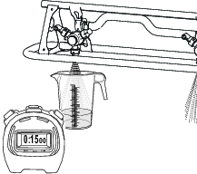
-
At 15-seconds, remove the catch container from the nozzle, and move to the operator’s seat.
-
On the control console in step 2 of 4 in the auto flow calibration wizard, when the time counter reaches 60-seconds—set the master section switch of the machine to the OFF position.
Note: The pulse counter and estimated volume counter stop. The time counter runs until you move to step 3 of 4 in the auto flow calibration wizard.
-
Set the throttle to the slow position, and shut off the spray pump.
-
In step 2 of 4 in the auto flow calibration wizard, press the next icon.
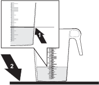
Calculating the 60-Second Sprayer Volume
-
Set the graduated container on a level surface, allow the fluid to settle, and note the fluid volume .
Important: Ensure that the graduated container is on a level surface.Small errors reading the fluid volume in the graduated container will significantly impact the accuracy of the sprayer calibration.
-
Using the fluid amount collected from the 1 nozzle, multiply 12 (the number of nozzles),to calculate the 15-second sprayer volume.
Step 1 Measurement 15-Second Sprayer Volume (ml or oz) x 12 = (ml or oz) Example: 44 fl oz X 12 nozzles = 528 fl oz
-
Multiple the 15-second sprayer volume that you calculated in step 2 by 4 to calculate the 60-second sprayer volume.
15–Second Sprayer Volume 60-Second Sprayer Volume (ml or oz) x 4 = (ml or oz) Example: 528 fl oz X 4 = 2112 fl oz
-
Convert that 60-second sprayer volume into liters or gallons (33.8 oz equals 1 liter; 128 fl oz equals 1 US gallon).
Record the converted volume here: (L or US gal).
Example: 2112 fl oz / 128 = 16.5 US gal
Entering the Converted 60-second Sprayer Volume
-
In step 3 of 4 in the auto flow calibration wizard, press the VOLUME CAPTURED icon, enter the fluid volume that you converted above with the on-screen keypad, and press the confirm icon.
-
Press the next icon.
-
In step 4 of 4 in the auto flow calibration wizard, press the confirm icon.
The 'pulses/gal' should be less than 400. If the value is higher, run the test again.
Creating a Field
Note: Create 1 field per course with all field boundaries for that course within that field.
-
Press the FIELD MENU icon, and press the NEW FIELD icon.
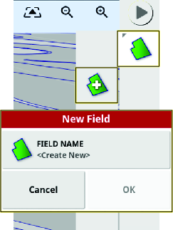
-
Press the FIELD NAME icon.
-
Enter the field name with the on-screen keyboard, and press the confirm icon.
-
In the new field dialog box, press the confirm icon.
Note: The new field becomes the active field.
Creating a Boundary
Refer to Recording a Field Boundary.
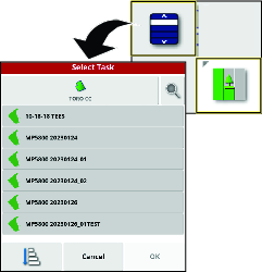
Creating a Spray Task
A spray task only relates with 1 field. A spray task cannot spray boundaries between multiple fields.
-
Press the TASK MENU icon and then the CREATE TASK icon.
-
In the new task window:
-
Select TASK NAME to update the new task name (optional).
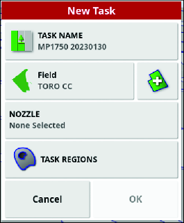
-
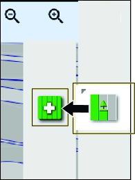
Choose a field or create a new one.
Note: It will default to the active field.
-
Select a nozzle.
-
Configure the task region; refer to Configuring a New Task Region.
-
Product Overview
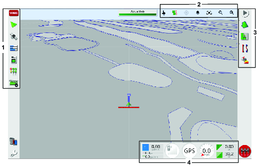
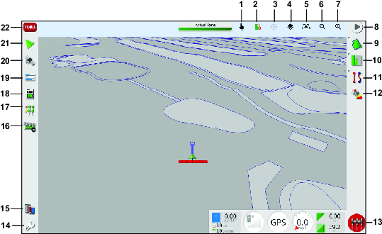
Select anywhere on the dashboard to customize what is shown.
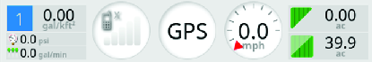
Swipe up from the bottom of the screen to access this control panel.

| Icon | Icon Description | Icon | Icon Description |
|---|---|---|---|
 | Turns the display off and on. |  | Press this icon to view screen layout options. |
 | Displays the name of each icon. A question mark will display next to each icon. Touch an icon to see the icon name. |  | Press this icon to see the list of saved global home screens or to toggle between saved screens. |
 | Press this icon before removing the USB from the display. |  | Lowers the brightness of the screen |
 | Press this icon to take a screenshot. |  | Brightens the screen |
 | Press this icon to capture a video. |  | Press this icon to choose between day, night (dark), and auto display options. Auto mode will set the display option automatically, depending on the light conditions. |
Operation
The computer in the automatic section controller (ASC) controls the spray application rate for varying vehicle speeds. You set the target volume per unit area to spray, and the ASC automatically maintains the flow within the proper range of the vehicle speed and continually displays the actual volume of material per area sprayed. The X console also monitors the area sprayed, the speed of the vehicle, and the total volume of material sprayed.
Note: Ensure that the sprayer is calibrated correctly before starting to spray.
Note: Ensure that the InfoCenter is set to GeoLink before using the display to spray.
Operating the Spray System of the Machine
-
Set the 3 section switches (located in the control console of the machine) to the ON position.
-
Press the master-section switch on the machine.
-
Press the master-switch icon in the control-console display (Multi Pro 5800 turf sprayers only).
-
Drive into the spray area.
Note: The machine starts spraying when the sprayer crosses into the defined spray area with the ASC control mode set the FIELD BOUNDARY position.
Note: The display shows areas you will spray as light gray and non-spray areas as dark gray. If the display shows all light gray, you can spray every area.
Selecting a Language and Accepting the License Agreement
The screen that follows the splash screen displays the language selection and the EULA (end user license agreement).
-
If needed, press the languages icon to change the display to a different language.
Note: Setting the language in the EULA screen changes the language setting throughout the user interface. You can also change the language in the User settings.
-
Read the EULA.
Use the scroll bar to navigate to the bottom of the screen. The YES icon will change to green.
-
Press the YES icon to move to the home screen.
Using the Master Switch on the Control Console
Note: The master switch is connected to the task button. Select or create a task to enable to master switch; refer to Understanding the Task Button.
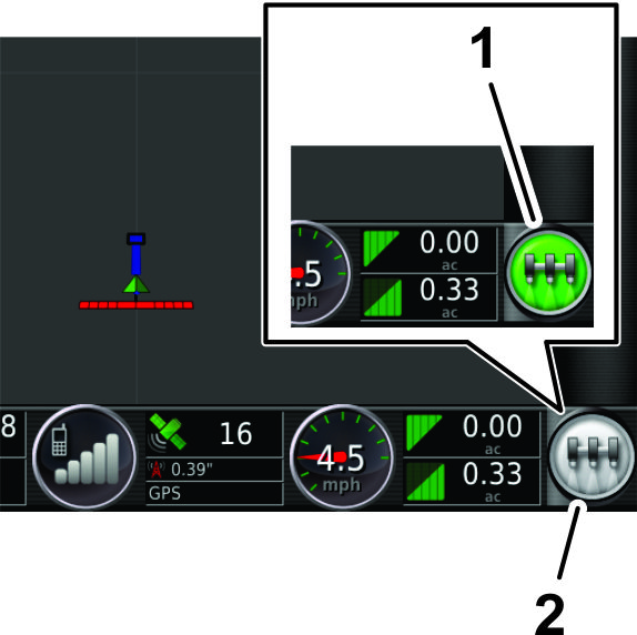
The MASTER SWITCH icon indicates the readiness of the system by the following colors:
-
Green—indicates that the system is ready, and the sprayer controller is enabled and able to spray.
-
White—sprayer controller is in standby.
-
Red—indicates that the system is not ready, the sprayer controller is disabled and unable to spray.
When the MASTER SWITCH icon is red, press the icon to display the master switch status dialog box, which shows the number of active alarms.
At any time, press the confirm icon to return to the main screen and complete the necessary corrective action.
Using the Master Switch
The MASTER SWITCH icon on the home screen indicates the sprayer system is on or off.
Using the Master Switch
The MASTER SWITCH icon on the home screen turns the sprayer system on or off. This switch does not work if the master-section switch or the left, center, and right section switches of the machine are in the OFF position; refer to the Operator’s Manual for information about the master-section switch and the 3 section switches.
-
Press the MASTER SWITCH icon to run the sprayer system (the icon turns green).
-
Press the MASTER SWITCH icon to shut off the sprayer system (the icon turns white).
Information, Urgent, Caution, and Warning Messages
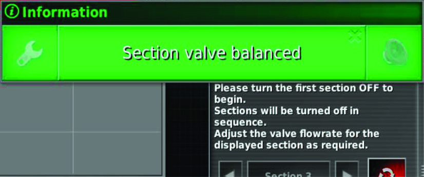 |
Information messages tell you the status of a process. |
||
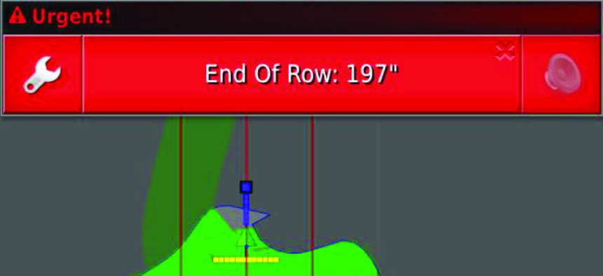 |
Urgent messages tell you that you need to act. |
||
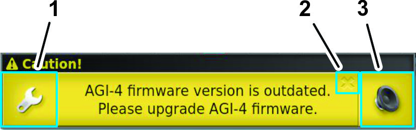 |
Caution messages tell you that you should to perform a corrective action before operating the machine. |
||
|
1. SETTINGS LINK icon |
2. CLOSE icon |
3. ALARM AUDIO SHUTOFF icon |
|
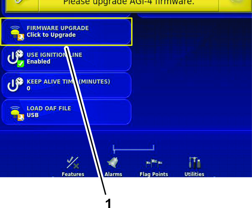 |
|||
|
1. Icon linked to the settings-menu screen |
|||
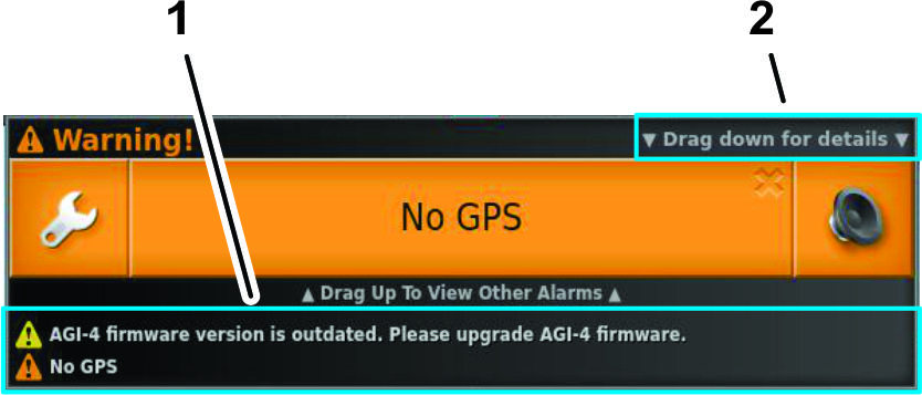 |
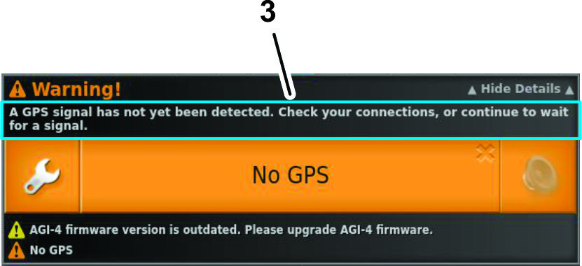
Warning messages tell you that you must to perform a corrective action before operating the machine. |
||
 |
|||
|
1. Corrective action information |
2. Details icon (swipe down) |
3. Message details |
|
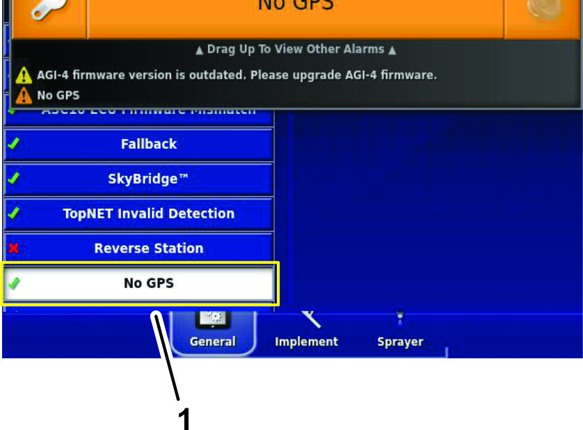 |
|||
|
1. Linked to the settings-menu screen |
|||
Using the Inventory Manager
USB Storage Device Specification
-
USB 3.0
-
8 GB or larger
-
Linux compatible
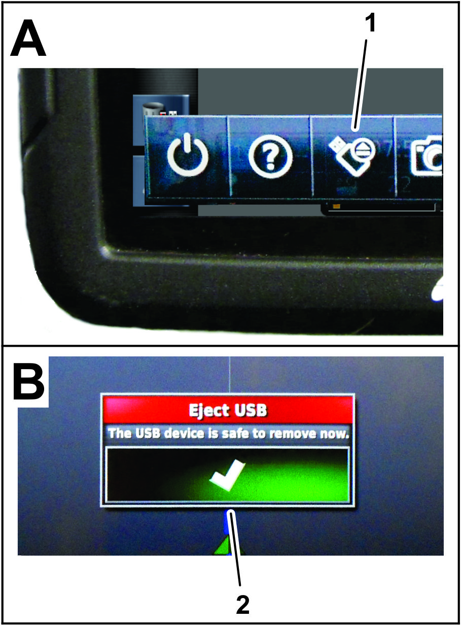
Using a USB Storage Device
-
Insert a USB storage device into the USB port.
-
Save or transfer information to and from the USB storage device using the inventory manager.
-
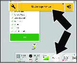
At the bottom of the control console screen, swipe up to access the floating-menu bar.
-
Press the eject USB icon.
-
At the eject USB dialog box, press the confirm icon and remove the USB storage device from the display.
Importing and Exporting
Open the INVENTORY MANAGER to import and export information. Press CATEGORIES to see what information can be exported.
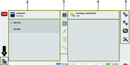
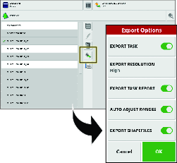
Exporting Tasks and Task Reports
-
Select tasks from the category drop down list.
-
Select the tasks in the list on the left.
-
Select the copy icon.
-
Choose which task data you want to export.
Note: Selecting export shapefiles will generate coverage, guideline group, and boundary shapefiles. These are saved in D:\Reports file under a time stamped folder.
Select Auto adjust ranges if required: If data exists that used a color legend, the colors used in the report map shading are altered so that the maximum variation in colors is used to illustrate yield rates.
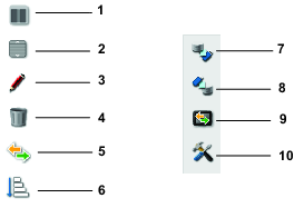
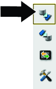
Creating a Backup
This option will back up all inventory items or user settings onto a USB.
Select the BACKUP icon.
Note: Existing data on the USB will be deleted.
Restoring a Backup File (All inventory)
This option restores all inventory items or user settings.
This function is typically used for service.
Select the RESTORE icon.
Note: This action will overwrite any data on the control console and is used to restore content from a backup USB.
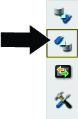
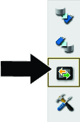
Exchanging Task Data
This function will copy or move all task data from the control console onto the USB.
-
Select the EXCHANGE TASK DATA icon.
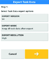
-
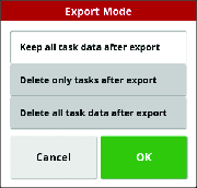
Select the export mode:
-
Keep all task data after export: All of the task data is saved on the control console.
-
Delete only tasks after export: All tasks are deleted from the control console but data such as fields, products, and implements is retained.
-
Delete all task data after export: All of the task data is deleted from the control console.
-
Managing Task Data
The task menu selects or sets up specific task information associated with the chosen area. Use this menu to store information, and record and report activity.
Understanding the Task Button
| Icon | Description | Master Switch Status |
|---|---|---|
 | Press this icon to create and start a new task. | |
 | Press this icon to start a task that is selected. | |
 | Press to display errors that are preventing the task from running. | |
 | A task is currently running and the data is being recorded. |  |
|
||
 | Press this icon to pause a task. | |
 | Press this icon to complete a task. | |
The master switch is connected to the task button. Select or create a task to enable the master switch to start spraying.
Creating a Spray Task
Refer to Creating a Spray Task
Selecting an Existing Task
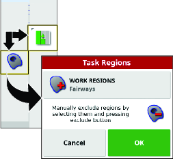
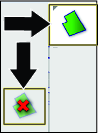
Configuring a New Task Region
-
Select a field, ensure that you have a boundary in the field, and the boundary is categorized.
-
Press the TASK MENU icon.
-
Press the CONFIGURE TASK REGIONS icon.
-
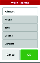
In the task region menu, select 1 of the following region types:
-
Press the WORK REGIONS icon that you are spraying (i.e., fairways, greens, or tees).
-
Press the EXCLUDED REGIONS icon that are not to be sprayed (bunkers, trees, hazards, etc.).
-
-
Press the confirm icon.
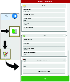
Recording Task Details
-
Select or create a new task.
-
Press the TASK MENU icon.
-
Press the task information icon.
-
Press the icons for the types of task information, enter the specific information, and press the confirm icon.
Information Types
Weather
Crop
Wind speed
Growth stage
Wind direction
Soil type
Temperature
Soil conditions
Humidity
Application method
Sky conditions
Clearing Task Information
You can clear information for the active task, including notes and counter data; the control console keeps the record-task information.
Note: Shared task information cannot be cleared.
-
Press the TASK MENU icon.
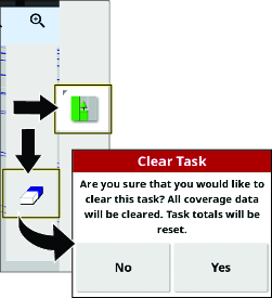
-
Press the CLEAR TASK DATA icon.
-
Press the Yes icon in the clear task dialog box.
Managing Field Information
Selecting a Field
-
Press the FIELD MENU icon and press the SELECT FIELD icon.
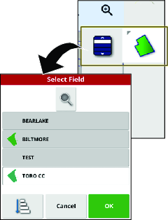
-
In the select field list, press the Field icon for the field you are spraying, and press the confirm icon.
Note: Unload the selected field by pressing the FIELD MENU icon and press the UNLOAD FIELD icon.
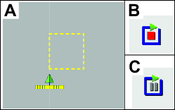
Recording a Field Boundary
Important: The boundaries that you create and save are accurate and repeatable only if the boundary is created while operating with a fully-fixed RTK correction.
Starting the Record Boundary
-
Drive the machine to the active field for job site.
-
Align the outside, center part of the left front tire at the starting point of the new field boundary.
-
Press the FIELD MENU icon, and press the RECORD FIELD BOUNDARY icon.
-
Drive the machine around the field to define the field boundary perimeter.
Note: You can drive as slow as needed and stop the machine as needed while recording the field boundary.
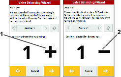
Pausing the Record Boundary
You can pause recording the field boundary if you need to move the machine into an area with limited space.
-
Stop the machine.
-
Press the PAUSE FIELD BOUNDARY RECORDING icon.
-
Align the machine into position.
-
Press the RECORD FIELD BOUNDARY icon to begin recording again, and continue driving the machine to define the boundary perimeter.
Note: When you resume recording the boundary, the system draws a straight line from the location where you paused recording to the location where you resumed recording the boundary.
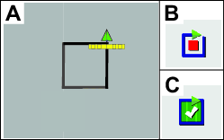
Completing a Boundary
-
When you are close to the beginning point of the field boundary, stop the machine.
-
Press the COMPLETE FIELD BOUNDARY RECORDING icon.
Note: The control console connects the beginning and end points with a straight line.
Creating a Boundary with All Straight Sides
-
Align the outside, center part of the left front tire at the first point of the straight sided field boundary, and stop the machine.
-
Without moving the machine, press the RECORD FIELD BOUNDARY icon, and press the PAUSE FIELD BOUNDARY RECORDING icon.
-
Move the machine, and align the outside, center part of the left front tire at the next point of the straight sided field boundary, and stop the machine.
-
Press the RECORD FIELD BOUNDARY icon, and press the PAUSE FIELD BOUNDARY RECORDING icon.
Note: The control console connects the 2 points with a straight line.
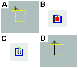
-
Repeat steps 3 and 4 for all the remaining points except for the last open point.
-
Align the outside, center part of the left front tire at the last point, and stop the machine.
-
Press the COMPLETE FIELD BOUNDARY RECORDING icon.
Note: The control console connects the beginning and end points with a straight line.
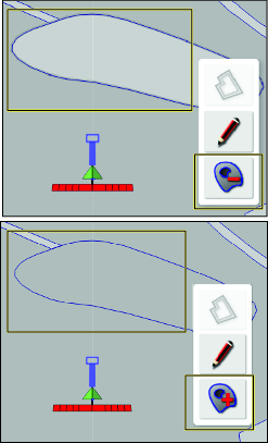
Creating a Boundary from Coverage
This procedure describes how to create boundaries from areas of previously recorded coverage. With only the center spray section spraying water, you can use this procedure to create exclusion boundaries for golf cart paths.
-
Park the machine near the coverage area from which you are creating a field boundary.
-
Press the Field icon and press Create Boundary from Coverage icon.
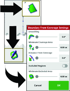
-
Press the number icon or sliders to update the settings.
-
The smoothing setting controls the minimum gap size that is automatically filled when creating a field boundary from coverage.
-
The minimum coverage area setting to exclude coverage smaller that the area specified (not included in the field boundary).
-
The distance from coverage setting to expand the created field boundary the specified distance away from the coverage.
-
The minimum excluded area setting is used to control exclude regions are not created from gaps smaller than the area you specify in minimum exclude area setting.
-
-
Press the EXCLUDED REGIONS icon to create boundaries for coverage areas that are not sprayed.
Note: Enabling exclude regions creates exclude regions from gaps within the coverage area.
Editing Field Boundary Attributes
Field boundary attributes are used to uniquely identify the boundaries within a field, and indicate to the system areas where product is applied or not applied.
-
Work Region—work regions indicate to the system areas where product is always applied if you use auto section control. Use work regions for areas such as fine and course turf grass.
-
Excluded Region—excluded regions indicate to the system areas where product is never applied if you use auto section control. Use excluded regions for areas such as water features, sand features, and walking or cart paths.
-
Categorized Region
-
Categorized regions are used for fields with many boundaries.
-
Assigning each boundary to a category is useful when including boundaries when applying a product or excluding a boundary when applying another product.
-
You can use categorized regions to define work regions and excluded regions for the current task.
-
In addition to the preset categorized regions, you can create new categorized regions for unique boundary-product application or unique boundary-product exclusion.
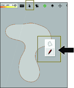
After creating the boundary, press your finger on the control console screen next to the boundary line until the boundary-selection icon illuminates, and slid your finger to the boundary line. Remove your finger from the screen, and the edit boundary dialog box opens.
-
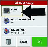
Naming a Field Boundary
Press the name icon, use the on-screen keyboard to type in the boundary name, and press the confirm icon.
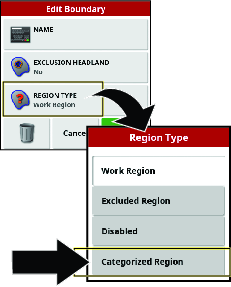
Setting a Work Region Field Boundary
-
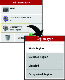
In the edit boundary dialog box, press the REGION TYPE icon.
-
In the regions type dialog box, press the WORK REGION icon.
-
Select the work regions type and press the confirm icon.
Setting an Excluded Region Field Boundary
Note: Setting an excluded region field boundary permanently excludes spraying the area in the boundary of the field. An excluded region field boundary is different from configuring in the spray task with an excluded region.
-
In the edit boundary dialog box, press the REGION TYPE icon.
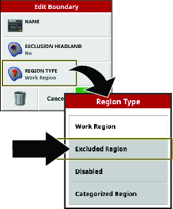
-
Select the region to exclude and select the region icon with the minus sign.
Note: Select the region icon with the plus sign to include the region again.
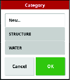
Setting a Categorized Field Boundary
-
In the edit boundary dialog box, press the REGION TYPE icon.
-
In the regions type dialog box, press the CATEGORIZED REGION icon, and press the Confirm icon.
-
In the edit boundary dialog box, press the CATEGORY icon to display a list of category types.
-
In the category types list, press the icon for a preset category types, or select the NEW . . . icon.
-
The selected category type displays, and press the confirm icon.
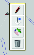
Flag Points
You add flag points to the control console map while you are creating field boundaries or spraying to identify terrain features or hazards for the site.
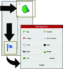
Setting a Flag Point
-
Drive the machine to the location of the terrain feature that you want to mark with a flag point, and stop the machine.
-
Press FIELD MENU icon and the SET FLAG POINT icon.
The add flag point menu displays.
-
In the add flag point menu, select a flag point icon.
The flag point displays in the control console behind the vehicle.
Note: The flag point drop location is beneath the machine, at the centerline, and between the rear tires.
Setting a Custom Flag Point
-
Drive the machine to the location of the terrain feature that you want to mark with a flag point, and stop the machine.
-
In the add flag point menu, press FIELD MENU icon and the SET FLAG POINT icon.
-
Press the CUSTOM flag point icon.
The add flag point dialog box displays.
-
In the add flag point dialog box, press a flag point icon, and press the FLAG POINT NAME icon.
The on-screen keyboard displays.
-
Use the on-screen keyboard to type the name of the custom flag point, and press the confirm icon.
-
In the add flag point dialog box, press the confirm icon.
The flag point displays in the control console behind the vehicle.
Editing Flag Points
-
Press your finger on flag point in command console screen until the flag point pop-up displays.
-
Remove your finger from the screen.
The flag edit menu displays.
Changing a Flag Point Type
-
In the edit flag menu, press the CHANGE icon.
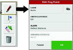
-
In the change flag point menu, change the name, icon, obstacle radius, or the alarm distance.
Moving a Flag Point
-
In the edit flag menu, press the MOVE icon.
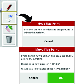
-
Drag the flag icon to a new location and press the confirmation icon.
Deleting a Flag Point
-
In the edit flag menu, press the DELETE icon.
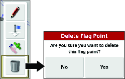
-
In the delete flag point dialog box, press the YES icon.
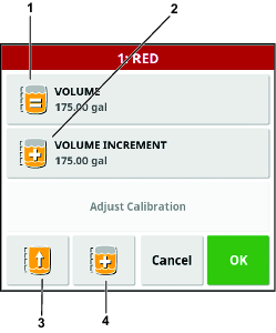
Setting the Tank Volume
-
Press the SPRAYER MENU icon.
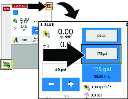
-
Press the VOLUME icon.
-
Use the numeric pad of the display to enter 1 of the following:
Note: Press the INCREMENT VALUE or DECREMENT VALUE icons to enter a preset increment of product volume quantity.
-
If you are entering a final product volume into the tank (such as water and chemicals), enter the total volume of product that you will add product to the tank, press the confirm icon, and press the confirm icon on the tank fill window.
Note: The volume of water and product is less than or equal to the configured tank capacity.
-
If you are incrementally adding chemicals to water, enter the volume of water in the tank , press the confirm icon, and proceed to step 4.
Note: The volume of water and product is less than or equal to the configured tank capacity.
-
-
If you are incrementally adding chemicals to water, press the VOLUME INCREMENTS icon.
-
Use the numeric pad of the display to enter increment of the volume of product (such as chemicals to water) that you will add product to the tank, and press the confirm icon.
Example: 19 L (5 gallon), 114 L (30 gallon), or 208 L (55 gallon) increments.
-
If you are incrementally adding chemicals to water, add the product into the tank and press the INCREMENT AMOUNT OF PRODUCT icon.
-
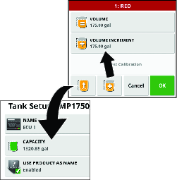
If you are filling the tank to capacity with a product or water, you can press the FILL TANK TO CAPACITY icon.
-
Press the confirm icon and press the confirm icon on the tank fill window.
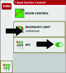
ASC Boom Control
Setting the Control Mode
Note: This setting controls the amount of nozzle-spray overlap for adjacent sprayer passes at the outermost spray nozzles (as a percentage of the spray pattern).The default setting is 50.
-
Press the AUTO SECTION CONTROL icon.
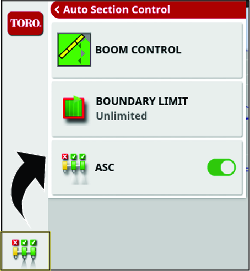
-
Press the BOOM CONTROL icon.
-
Set the percentage in CONTROL MODE to avoid overlapping (0) or to avoid gaps (100).
-
Avoiding overlapping could cause spaces where the product is not applied.
-
Avoiding gaps could cause some overlap of application.
-
-
Set the distance in OVERLAP ENTERING COVERED AREA to set the amount of overlap to occur when entering a completed area.
-
Set the distance in OVERLAP EXITING COVERED AREA to set the amount of overlap to occur when exiting a completed area.
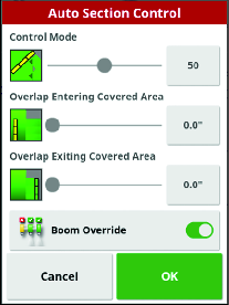
-
-
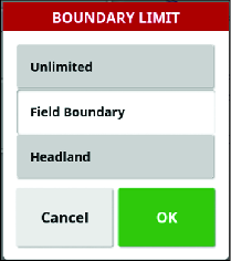
Set the Boundary Limit.
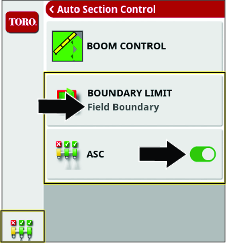
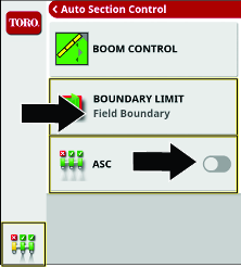
Choosing a Spraying Method
|
Auto Section Control |
Boundary Limit |
Rate Control |
Description |
|
|---|---|---|---|---|
|
Field Boundary | On | Field Boundary | Auto |
|
|
Unlimited | On | Unlimited | Auto |
|
|
Manual Section Control | Off | Field Boundary | Auto |
|
|
Full Manual Control | Off | Field Boundary | Manual |
|
Automatic Section Control
|
Setting |
Description |
|---|---|
|
ASC ON |
The machine controls the operation of the individual nozzle sections. |
|
ASC OFF |
The operator controls the nozzle sections as groups with the left, center, and right spray-section switches. |
Boundary Limit
|
Setting |
Description |
|---|---|
|
FIELD BOUNDARY |
The machine turns on nozzle sections as the turf sprayer enters the field boundary of a work region. |
|
The machine turns off nozzle sections as the turf sprayer enters excluded regions within the work region. |
|
|
The machine turns off nozzle sections as the turf sprayer exits the field boundary of a work region. |
|
|
The machine turns off nozzle sections where pass-to-pass spraying overlaps. |
|
|
UNLIMITED |
The machine controls the nozzle sections with pass to pass control, but without any field boundary. |
|
The machine turns off nozzle sections where pass-to-pass spraying overlaps. |
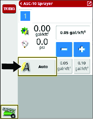
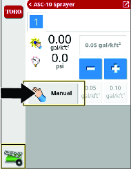
Rate Control
|
Setting | Description |
|---|---|
|
Automatic (Auto) |
The machine controls the application rate based on the rate that you set for the active spray task or the rate you set in the sprayer control panel. |
|
Manual |
The operator controls the application rate while spraying. |
|
Pressure |
The machine operates to the pressure that you set for the active spray task. |
Configuring the Machine for Each Spray Method
Field Boundary Spraying Method
|
Auto Section Control |
Boundary Limit |
Rate Control |
Description |
|
|---|---|---|---|---|
|
Field Boundary | On | Field Boundary | Auto |
|
 |  |
|||
Unlimited Spraying Method
|
Auto Section Control |
Boundary Limit |
Rate Control |
Description |
|
|---|---|---|---|---|
|
Unlimited | On | Unlimited | Auto |
|
 | |
|||
Manual Section Control Spray Method
|
Auto Section Control |
Boundary Limit |
Rate Control |
Description |
|
|---|---|---|---|---|
|
Manual Section Control | Off | Field Boundary | Auto |
|
 | |
|||
Full Manual Spray Method
|
Auto Section Control |
Boundary Limit |
Rate Control |
Description |
|
|---|---|---|---|---|
|
Full Manual Control | Off | Field Boundary | Manual |
|
|  |
|||
Configuring the Sprayer Controls for a New Task
Creating a Spray Nozzle
Note: The standard ISO list is already loaded in the display.
-
Click on NEW NOZZLE... or COPY SELECTED NOZZLE from the IMPLEMENT setup screen.
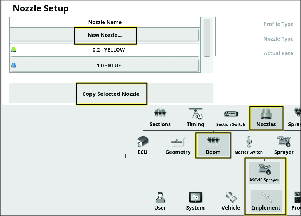
-
Go through the create nozzle setup wizard.
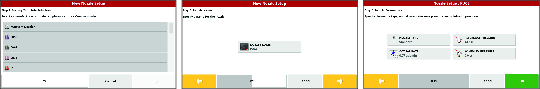
-
Your new nozzle will now appear in the task nozzle menu.
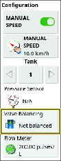
Selecting the Spray Nozzle—Balancing the Nozzle Valves
Important: When you create a task, the nozzle size to which the GeoLink system is controlled shows on the display. You must use the valve balance wizard each time you change spray nozzles.
-
Fill the sprayer tank with clean water.
-
Ensure that the parking brake is engaged, and the gear selector is in the NEUTRAL position.
-
Start the engine, lower the boom sections, set the machine master-section switch to the OFF position, and set the 3 section switches to the ON positions.
-
Ensure that the agitation bypass valve is balanced, and that the spray system pressure is more than 207 kPa (30 psi); refer to your Operator's Manual.
-
Press the spray rate controller icon, and then swipe the full screen icon in the upper right corner of the sprayer controller window.
-
Press the configuration icon, and then press the valve balance wizard icon.
-
Go through the wizard.
-
Select the nozzle.
Note: If the nozzle for the application rate that you are spraying does not appear in the list, you will need to create a new nozzle before using the valve balancing wizard.
-
Set the pressure rate to 2.75 bar (40 psi).
-
Bring the throttle to 1/2 to 3/4 full throttle and set the throttle lock.
-
On the machine, set the master-section to the ON position.
-
Wait for the system flow rate to stabilize and the lock icon to appear in the dialog box.
-
Press the section On/Off icon to shut off the section valve (red).Press the next icon.
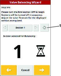
-
Adjust the pressure as needed.
-
Once the section is balanced, an information screen is displayed and the next section will turn off.
-
Ensure that all the bypass valves are adjusted and press the confirm icon.
Note: If the nozzle valves will not balance, lower the engine speed and go through the wizard again.
-
| Nozzle | Nozzle Color | Flow Rate |
|---|---|---|
 0.2 0.2 | Yellow | 0.8 lpm (0.2 gpm) |
 0.4 0.4 | Red | 1.5 lpm (0.4 gpm) |
 0.5 0.5 | Brown | 1.9 lpm (0.5 gpm) |
 0.6 0.6 | Gray | 2.3 lpm (0.6 gpm) |
 0.8 0.8 | White | 3.0 lpm (0.8 gpm) |
 1.0 1.0 | Blue | 3.8 lpm (1.0 gpm) |
 1.5 1.5 | Green | 5.7 lpm (1.5 gpm) |
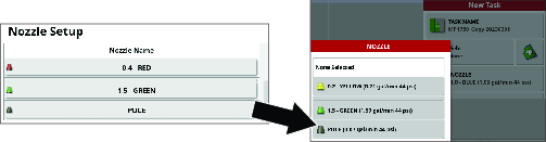
Selecting the Spray Nozzle
-
In the new task menu, press the nozzle icon.
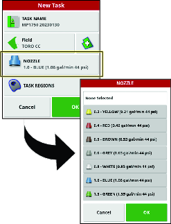
-
In the drop-down list, select the nozzle for the application rate that you are spraying.
Note: If the nozzle for the application rate that you are spraying does not appear in the list, you will need to create a new nozzle before using the valve balancing wizard.
-
Press the confirm icon.
MachineLink
Converting Legacy Data (M2M-Retro Kit Only)
Use this process to bring over data from your 4.xx software and convert it to 5.xx software.
Important: Ensure that you have installed the high gain antenna; refer to the GeoLink Finishing Kit for your model.
-
Navigate to the UTILITIES screen and select CONTROL SOFTWARE UPGRADE.
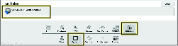
-
Insert the MachineLink USB into the back of the display.
-
Navigate to the LICENSES screen and select IMPORT LICENSE DATA.
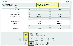
-
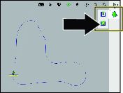
Enable MachineLink.
Enabling MachineLink
MachineLink enables coverage to be shared between multiple implements operating in the same field.
Note: Ensure that you have the high-gain antenna connected to the modem; refer to the Geolink Finishing Kit.
-
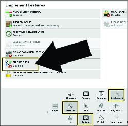
In SETUP, go to SYSTEM, FEATURES, then IMPLEMENT.
-
Change MACHINELINK to enabled.
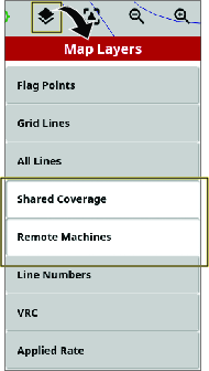
-
Ensure that SHARED COVERAGE is highlighted in the MAP LAYERS MENU.
-
Shared coverage will show the coverage of MachineLink machines in the same field.
-
Remote machines will show vehicles on the map that are connected to the network.
-
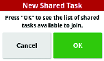
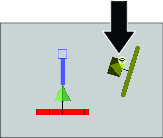
Joining a Shared Task
MachineLink enabled machines nearby are notified that a new shared task is available; refer to Enabling MachineLink
-
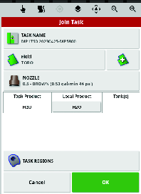
Select OK or select the JOIN TASK option in the TASK MENU.
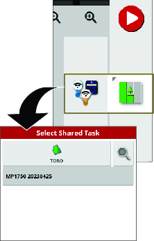
-
Select a task to join.
Note: The product being applied remotely must match the products in the local implement.
The system will match the products being used remotely to the products on the local machine by:
-
Matching the products that have been previously linked.
-
Matching the name of the products.
-
Matching the previous assignment or name of the products.
The below screen will display if the products do not match.
-
Task product will display the product being applied remotely.
-
Local product will display the product being applied locally.
-
Tank(s) will list the tank containing the product.
-
-
Press OK to join the task.
Note: A notification will be sent to the machine that started the task.
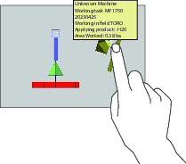
Using MachineLink
-
Machines will have a symbol to show if they are connected or not.
Note: The Wi-Fi antenna will connect up to 0.4 km (0.25 mile).
-
Press and hold the icon on the machine to display:
Note: If the Wi-Fi connection is lost, the machine icon will show that it is disconnected and it stay in the last connected position until connection is regained. When the Wi-Fi connects, the machine appears in the actual position and the display will show the updated shared coverage.
-
The console name
-
The status and any connection issues
-
Which products are being applied
-
The areas that have been covered
-
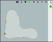
Shared Coverage
Local coverage displays as a light green.
Shared coverage displays as a dark green. Press the machine icon to highlight the shared coverage in a different shade to show the specific coverage from that implement.
Creating a ‘boundary from coverage’ uses the local and shared coverage to form the boundary.
The application rate can be selected as a coverage option. Since all machines shares the same coverage legend, they will have the same application rate map.
If you change fields or tasks on a display but then go back to the previous shared task, the shared coverage will not show up unless the other machines are still operating in that field or they reload the shared task.
If a machine leaves the shared coverage field, that machine’s coverage will still be displayed.
Note: The total covered area only displays the area covered from the local implement. The remaining area calculated within a boundary will not factor in the shared coverage.
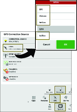
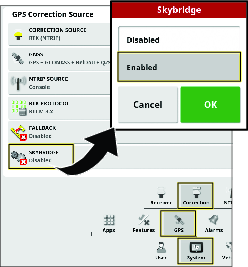
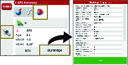
Configuring Skybridge Settings
-
Press the SETUP menu.
-
Navigate to the GPS CORRECTION SOURCE menu via SYSTEM – GPS – CORRECTION.
-
Select GNSS and choose GPS, GLONASS, BEIDOU, AND GALILEO.
-
Select SKYBRIDGE and choose ENABLED.
-
Drive the machine to an open area and ensure that RTK is displayed on the dashboard.
-
Skybridge will converge within 30 to 40 minutes and RTK + SKYBRIDGE will display on the dashboard.
During operation, the dashboard displays the current correction status based on the strongest signal (RTK, Skybridge, Float RTK, or GPS) available at the given time and location.
Technical Assistance
For many errors an error code, or fault code, will display. It is also possible to view the errors on the screen. Some errors are common and are correctable. For other errors or if a problem persists, always record the error message including any code displayed and report to your distributor or Contact your authorized Toro distributor or Toro GeoLink Support.
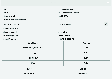
Identifying System Information
-
Press the System Information (Toro) icon at the top, left corner of the screen.
-
In the system information mini-view window, press the full-screen icon.
-
Use the scroll bar to view the following types of system information details:
-
Console
-
GPS receiver
-
Steering controller (optional kit)
-
Wireless network
-
Verifying the RTK and Correction Information
-
Move the machine outdoors, away from buildings and power lines.
-
Engage the parking brake.
-
On the GeoLink control console, press the GPS INFORMATION icon.
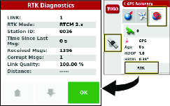
-
Press the RTK icon, and verify in the RTK diagnostics dialogue box that the RTK link quality is 50% or greater.
-
Press the confirm icon to close the dialog box.
Note: If the modem signal is equal to or less than -100 dBm, Contact your authorized Toro distributor or Toro GeoLink Support.If RTK link quality is less than 50%, Contact your authorized Toro distributor or Toro GeoLink Support.
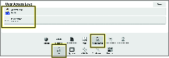
Remote Assist
Entering a Support Desk PIN
-
Contact Toro support to request a desk PIN code.
-
In the setup screen, press the USER icon, and press the REMOTE SUPPORT icon.
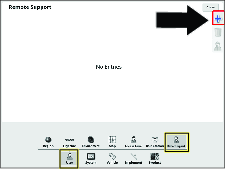
-
If no support desk entries appear in the remote support window, press the ADD SUPPORT DESK icon.
-
Press the DESK PIN icon.
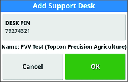
-
Enter the PIN code.
-
In the Add Support Desk screen, press the confirm icon.
Note: The control console saves the support desk information to memory.
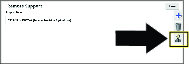
Connecting to the Support Desk Personnel
-
Press the SUPPORT DESK icon for customer service, saved to the support desk list.
-
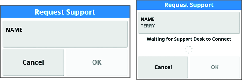
Press the REQUEST SUPPORT FROM DESK icon.
The request support screen dialog box appears, then the support session active dialog box appears.
Note: The customer service representative remotely connects to the control console.
Operating Tips
Improving the RTK Correction
Reduce the machine speed, or approach from another direction, when you are approaching an area with known RTK correction difficulty.
Using the Manual Control
To boost pressure for the hose reel and mixing chemicals, use the manual control to boost pressure.
Improving the Application Rate Response Time
Set the agitation PWM (preset agitation value) to approximately 69 kPa (10 psi) above the target-spraying pressure.
Creating a Backup File of the Display Data
Refer to Using the Inventory Manager.
Cleaning the Display Screen
Clean the screen, when needed, with mild soap and water.
Note: Avoid using window cleaners and any cleaners with solvents.
Troubleshooting
| Problem | Possible Cause | Corrective Action |
|---|---|---|
| There is no power to the display. |
|
|
| The sprayer does not spray. |
|
|
| The No GPS alarm is on. |
|
|
| The sprayer sprays outside boundaries. |
|
|
| You cannot create boundaries. |
|
|
| The machine is not shown on the screen. |
|
|
| The lights are not blinking on the GPS receiver located on the ROPS. |
|
|
| The pressure is not high enough. |
|
|
| The controller lights not on at the ASC 10 controller. |
|
|
| The speed is not displayed in the control console when the machine is moving. |
|
|
| There is condensation inside the display of the control console. |
|
|
| The control console displays a crash report notification. |
|
|