Safety
Warning
The blades are sharp; contacting a blade can result in serious personal injury.
Wear gloves when servicing the blades.
Safety and Instructional Decals
 |
Safety decals and instructions are easily visible to the operator and are located near any area of potential danger. Replace any decal that is damaged or missing. |
Installation
Preparing the Machine
-
Shut off the engine, wait for all moving parts to stop, and allow the machine to cool.
-
Disconnect the wire from the spark plug.
-
Lift the front of the machine using an appropriate lifting device or jack stands.
Note: If using jack stands, use the front lip of the deck to hold the machine up. Place blocks behind the rear wheels to prevent the machine from moving.
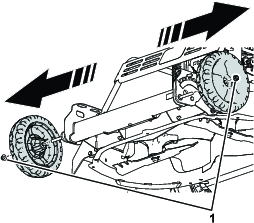
Removing the Existing Wheels
Remove the wheel nuts securing the front wheels. Remove the wheels from the wheel bolts and retain the wheels.
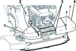
Removing the Bumper Assembly
-
Remove the engine shield and arms.
-
Remove the engine shield. Retain it and the fasteners for later installation.
-
Remove the carriage bolts securing the engine shield arms to the height-of-cut brackets and the bumper assembly. Remove and discard the engine shield arms.
Retain the height-of-cut bracket fasteners for later installation.
-
-
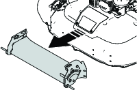
Remove the fasteners securing the front bumper assembly to the deck.
Retain the fasteners for later installation.
-
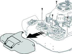
Remove the front bumper assembly.
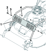
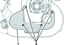
Removing the Belt Cover
Remove the 4 flange-head bolts securing the belt cover. Remove the belt cover and retain the bolts for later installation.
Note: If your machine has a Kohler® engine, a push-in fastener instead of a bolt will be in the rearmost hole of the belt cover.
Installing the Belt Cover
Parts needed for this procedure:
| Right belt cover | 1 |
| Left belt cover | 1 |
-
Install the right belt cover to the deck using the previously removed bolts or fasteners.
-
Slide the tabs of the left belt cover into the right belt cover. Secure the left belt cover using the remaining fasteners.
Note: Ensure that the tabs are inserted into the belt cover, not over the top of the belt cover.
Assembling the Front Caster Assembly
Parts needed for this procedure:
| Front caster assembly | 1 |
| Hex-head bolt (3/8 x 3-3/4 inches) | 2 |
| Washer | 2 |
| Spacer | 2 |
| Locknut (3/8 inch) | 2 |
| Spring | 2 |
Install the previously removed wheels to the caster forks on the front caster assembly using 2 hex-head bolts (3/8 x 3-3/4 inches), 2 washers and spacers, and 2 locknuts (3/8 inch). Torque the locknuts to 37 to 44 N·m (27 to 33 ft-lb).
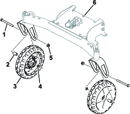
Note: If the bolt does not go through the holes in the caster fork, flex the wheel slightly so that the bolt and holes are aligned, then push the bolt through.
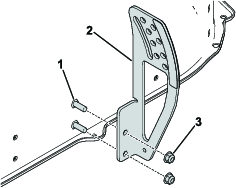
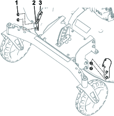
Installing the Height-of-Cut Plate
Parts needed for this procedure:
| Height-of-cut plate | 1 |
| Hex-head bolt (5/16 x 7/8 inch) | 2 |
| Locknut (5/16 inch) | 2 |
Caution
Using a drill without proper eye protection may allow debris to enter the eyes, causing injury.
When drilling, always wear eye protection.
-
Drill 2 holes (8 mm or 5/16 inch) into the front of the deck as shown in Figure 10.
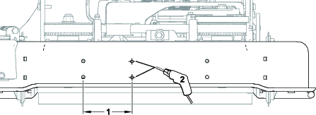
-
Secure the height-of-cut plate to the holes in the deck using 2 hex-head bolts (5/16 x 7/8 inch) and 2 locknuts (5/16 inch). Torque the locknuts to 20 to 25 N·m (175 to 225 in-lb).
Installing the Front Caster Assembly
Parts needed for this procedure:
| Hex-head bolt (5/16 x 7/8 inch) | 2 |
| Locknut (5/16 inch) | 6 |
| Engine guard bracket (left) | 1 |
| Engine guard bracket (right) | 1 |
| Engine guard arm (left) | 1 |
| Engine guard arm (right) | 1 |
| Carriage bolt (5/16 x 3/4 inch) | 4 |
-
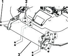
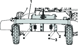
Install the assembled front caster assembly from Assembling the Front Caster Assembly to the front of the deck using carriage bolts (5/16 x 3/4 inch) and locknuts (5/16 inch) previously removed in step 2 of Removing the Bumper Assembly.
-
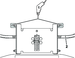
Using the caster bracket tabs as a template, drill 2 holes (8 mm or 5/16 inch) into the top of the deck as shown in Figure 13.
-
Insert 2 hex-head bolts (5/16 x 7/8 inch) through the top of the deck and secure with 2 locknuts (5/16 inch). Torque the locknuts to 20 to 25 N·m (175 to 225 in-lb).
-
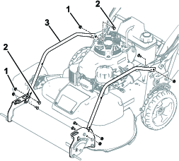
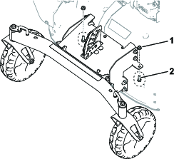
Install 2 engine guard brackets to the sets of holes at the front of the mower using the 4 carriage bolts and 4 locknuts previously removed in step 2 of Removing the Bumper Assembly.
-
Install 2 engine guard arms to the height-of-cut brackets using the 2 carriage bolts and 2 locknuts previously removed in step 2 of Removing the Bumper Assembly. Torque the locknuts to 20 to 25 N·m (175 to 225 in-lb).
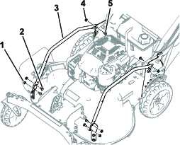
-
Using 4 carriage bolts (5/16 x 3/4 inch) and locknuts (5/16 inch), secure the engine guard arms to the engine guard brackets. Torque the locknuts to 20 to 25 N·m (175 to 225 in-lb).
-
Install the engine shield to the engine guard arms using the 2 hex-head bolts, 2 washers, and 2 locknuts previously removed in step 1 of Removing the Bumper Assembly.
Operation
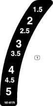
Adjusting the Cutting Height
Warning
Adjusting the cutting height could bring your hands into contact with a moving blade and result in serious injury.
-
Shut off the engine and wait for all moving parts to stop before adjusting the cutting height.
-
Do not put your fingers under the housing when adjusting the cutting height.
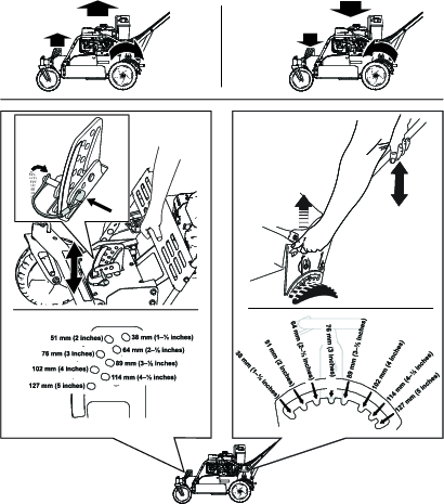
The cutting height is controlled by the front pin and the rear lever. The pin is at the front of the machine, and the lever is on the left side of the machine. To raise or lower the machine, remove the pin and engage the lever, raise or lower the machine, and lock the pin and disengage the lever.
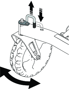
Unlocking the Casters
-
Lift the caster lock pins.
-
Turn and insert the pins into the holes on the axle.
Reverse the process to lock the casters.
Note: Lock the casters when you want the front wheels to remain straight (for example, when mowing the side of a hill).