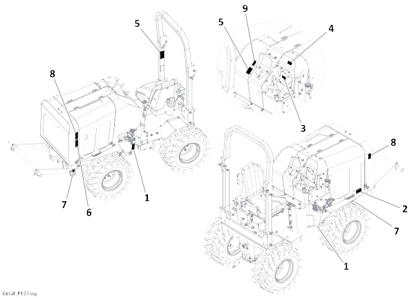
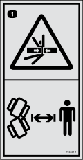
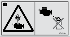
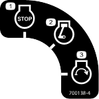
Disclaimers and Regulatory Information
It is a violation of California Public Resource Code Section 4442 or 4443 to use or operate the engine on any forest-covered,
brush-covered, or grass-covered land unless the engine is equipped with a spark arrester, as defined in Section 4442, maintained
in effective working order or the engine is constructed, equipped, and maintained for the prevention of fire.
Because in some areas there are local, state, or federal regulations requiring that a spark arrester be used on the engine
of this machine, a spark arrester is available as an option. If you require a spark arrester, contact your Authorized Service
Dealer. Genuine Toro spark arresters are approved by the USDA Forestry Service.
The enclosed engine owner's manual is supplied for information regarding the US Environmental Protection Agency (EPA) and
the California Emission Control Regulation of emission systems, maintenance, and warranty. Replacements may be ordered through
the engine manufacturer.
 |
| |
| CALIFORNIA |
| |
| Proposition 65 |
| |
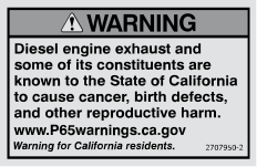
| The engine exhaust from this product contains chemicals known to
the State of California to cause cancer, birth defects, or other reproductive
harm. |
| |
| Battery posts, terminals, and related accessories contain lead and
lead compounds, chemicals known to the State of California to cause
cancer and reproductive harm. Wash hands after handling. |
| |
| Use of this product may cause exposure to chemicals known to the
State of California to cause cancer, birth defects, or other reproductive
harm. |
| |
FCC
This device complies with Part 15 of the FCC Rules. Operation is subject to the following conditions: (1) this device may
not cause harmful interference, and (2) this device must accept any interference received, including interference that may
cause undesired operation. Changes or modifications not expressly approved by Toro could void the user’s authority to operate the equipment.
Intended Use
This machine is an articulating, hydrostatic, four-wheel drive, ride-on vibratory plow designed to install cable and pipe
in a variety of soils. Optional trenching, drilling, and reel carrier attachments are available. Using this product for purposes
other than its intended use could prove dangerous to you and bystanders. Do not modify the machine or attachments.
This machine should be operated, serviced, and repaired only by professionals familiar with its characteristics and acquainted
with the relevant safety procedures.
Operate this machine in ambient temperatures from -12° to 46°C (10° to 115°F). Contact your Authorized Service Dealer for
provisions required for operating this machine in extreme temperatures.
Read this information carefully to learn how to operate and maintain your product properly and to avoid injury and product
damage. You are responsible for operating the product properly and safely.
Getting Help
Visit www.Toro.com for product safety and operation training materials, accessory information, help finding a dealer, or to register your product.
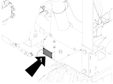
Whenever you need service, genuine Toro parts, or additional information, contact an Authorized Service Dealer or Toro Customer Service and have the model and serial numbers of your product ready. These numbers are located on the serial plate
on your product  . Write the numbers in the space provided.
With your mobile device, you can scan the QR code on the serial number decal (if equipped) to access warranty, parts, and
other product information.
|
Model Number:
|
|
Serial Number:
|
|
Manual Conventions
This manual identifies potential hazards and has safety messages identified by the safety-alert symbol, which signals a hazard
that may cause serious injury or death if you do not follow the recommended precautions.
This manual uses 2 words to highlight information. Important calls attention to special mechanical information and Note emphasizes general information worthy of special attention.
Safety Alert Classifications
The safety-alert symbol shown in this manual and on the machine identifies important safety messages that you must follow
to prevent accidents.
Safety-alert symbol appears above information that alerts you to unsafe actions or situations and is followed by the word
DANGER, WARNING, or CAUTION.
 |
Danger |
 |
Danger indicates an imminently hazardous situation which, if not avoided, will result in death or serious injury.
 |
Warning |
 |
Warning indicates a potentially hazardous situation which, if not avoided, could result in death or serious injury.
 |
Caution |
 |
Caution indicates a potentially hazardous situation which, if not avoided, may result in minor or moderate injury.
Jobsite Preparation
A successful job begins before working. The first step in planning is reviewing information already available about the job
and jobsite.
Reviewing the Job Plan
-
Review the blueprints or other plans. Check for information about existing or planned structures, elevations, or proposed
work that may be taking place at the same time.
Selecting the Start and End Points
-
Select an end to use as a starting point. Consider the following when selecting a starting point:
- Always park the equipment on a level site. Consider how the slope will affect setup and operation. Assess the risks on each
slope to determine if factors affecting risks create an unsafe condition for working.
- Check that the starting and ending points allow enough space for working.
- Consider how shade, wind, fumes, and other site features will affect operator comfort.
Identifying Hazards
-
Inspect the jobsite before transporting equipment; check for the following:
- Overall grade or slope
- Changes in elevation such as hills or open trenches
- Obstacles such as buildings, railroad crossings, or streams
- Signs of utilities
- “Buried utility” notices
- Gas or water meters
- Drop boxes
- Manhole covers
- Utility facilities without overhead lines
- Junction boxes
- Light poles
- Sunken ground
- Traffic
- Access
- Soil type and condition
- Loose material such as fencing or cable
Locating Utilities
-
Notify One-Call Services; mark the proposed path with white paint and have the underground utilities located before working.
- In the US or Canada, call 811 (US) or 888-258-0808 (US and Canada). Also contact any local utilities that do not participate
in One-Call service.
- In countries that do not have a One-Call service, contact all local utility companies to have underground utilities located.
-
Verify underground utilities; have an experienced locating equipment operator sweep the area within 6 m (20 ft) to each side
of the proposed excavation to verify previously marked line and cable locations. Mark the location of all buried utilities
and obstructions.
-
Locate overhead lines; note the location and height of all overhead lines in the jobsite and ensure that the equipment maintains
a proper distance from live lines.
Classifying the Jobsite
-
Survey the jobsite and classify the hazards that may be present.
Jobsites are classified according to the underground hazards present, not by the line being installed. A jobsite may have
more than one classification.
|
within 3 m (10 ft) of a buried electric line
|
Electric
|
|
within 3 m (10 ft) of a natural gas line
|
Natural gas
|
|
in concrete, sand, or granite which is capable of producing crystalline silica dust
|
Crystalline silica dust
|
|
within 3 m (10 ft) of any other hazard
|
Other
|
Classify the jobsite as electric if the jobsite is in question or if the possibility of unmarked electric utilities exists.
Once classified, take precautions appropriate for the jobsite. Follow the US Department of Labor regulations on excavating
and trenching (Part 1926, Subpart P) and other similar regulations.
Classified Jobsite Precautions
Electric Precautions
- Expose the line by careful hand digging or soft excavation.
- Have the service shut down while work is in progress.
- Have the electrical company test the lines before returning them to service.
Natural Gas Precautions
Position equipment upwind from the gas lines and use one or more of these methods:
- Expose the line by careful hand digging or soft excavation.
- Have the service shut down while work is in progress.
- Have the gas company test the lines before returning them to service.
Crystalline Dust Precautions
Crystalline silica dust is a naturally occurring substance found in soil, sand, concrete, granite, and quartz. To reduce exposure
when cutting, drilling, or working these materials:
- Use a water spray or other means to control the dust.
- Refer to the US Occupational Safety and Health Administration (OSHA) guidelines or other applicable regulating guidelines
for appropriate breathing protection or dust control methods.
Other Precautions
To safely avoid other underground hazards at each site, use different methods to determine the appropriate safety precautions.
Clear objects such as landscaping fabric, cable, and wire from the work area. These objects may be underground or partially
buried.
Arranging for Traffic Control
-
Keep the vehicle and pedestrian traffic away from the equipment. Evaluate the jobsite and allow an appropriate buffer zone
around the equipment. If the jobsite is near a road or other traffic area, contact the local authorities about safety procedures
and regulations.
Operator Preparation
Follow these guidelines before operating any jobsite equipment:
- Complete proper training and read the Operator’s Manual before using equipment.
- Plan for emergency services. Have the telephone numbers for local emergency and medical facilities on hand. Check that you
will have access to a telephone.
- Review jobsite hazards, safety and emergency procedures, and individual responsibilities with all personnel before work begins.
Safety Data Sheets (SDS) are available at www.Toro.com.
- Use equipment carefully. Stop operation and investigate anything that does not look or feel right.
Equipment Preparation
Installing Counterweights
-
Install counterweights as needed for attachments.
Mounting the Fire Extinguisher
-
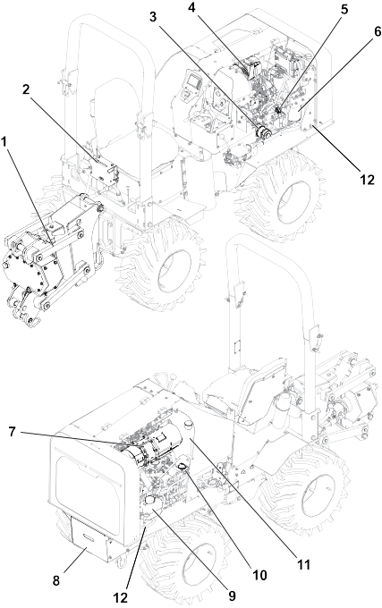
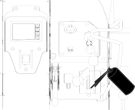
Mount a fire extinguisher near the engine but away from possible points of ignition where shown. The fire extinguisher should
always be classified for both oil and electric fires. It should meet legal and regulatory requirements.
G488934
- Plow
- Plow control
- Engine oil filter
- Air filter
- Engine oil cap
- Fuel water separator
- Diesel particulate filter
- Battery
- Coolant expansion tank
- Battery disconnect switch
- Hydraulic tank
- Hood lock
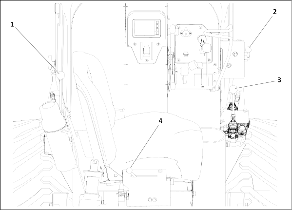
Controls
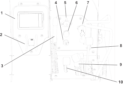
G484656
-
Display
-
Throttle
-
Parking brake
-
USB port
-
Auxiliary port
-
Horn
-
Key switch
-
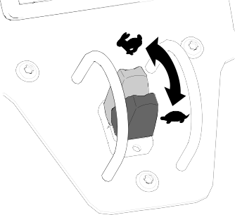
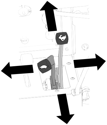
Traction control lever
-
Low speed traction control
-
Attachment control lever
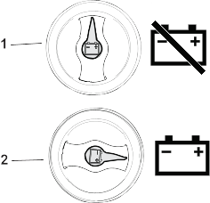
Battery Disconnect Switch
G419389
- Off—to de-energize the machine
electrically
- On—to energize the machine
electrically
Key Switch
G407265
- Stop engine
- Run engine
- Start engine
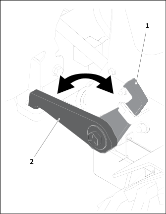
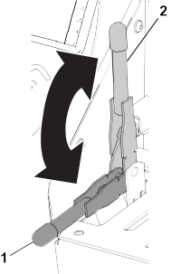
Attachment Control Lever
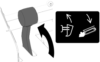
G407266
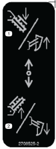
- Push the lever forward to raise the plow or lower the trencher.
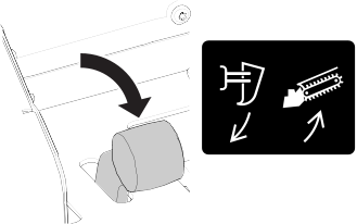
G407267
- Pull the lever rearward to lower the plow or raise the trencher.
Attachment Controls
G429253
-
Drilling attachment control
-
Attachment selector control
-
Digging chain control
-
Plow vibrator control
Attachment Controls Descriptions
|
|
Drilling attachment control
|
To rotate the drill clockwise, push toward the front of the machine.
To rotate the drill counterclockwise, pull toward the back of the machine.
|
|
|
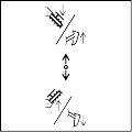
Attachment selector control
|
To select trencher, move up.
To select plow, move down.
|
|
|
Digging chain control
|
To start chain, push toward the front of the machine.
To reverse chain, pull toward the back of the machine.
|
|
|
Plow vibrator control
|
To start the plow vibration, push toward right side of machine.
To stop, pull back.
|
Display
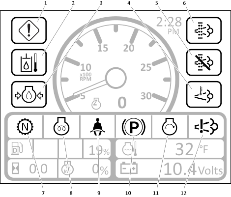
Indicators
G400644
-
Engine caution/stop indicator
-
Hydraulic fluid temperature indicator
-
Engine oil pressure indicator
-
High exhaust temperature indicator
-
Exhaust cleaning disabled indicator
-
Exhaust cleaning indicator
-
Neutral status indicator
-
Cold start wait indicator
-
Operator presence indicator
-
Parking brake indicator
-
Engine crank indicator
-
NOX control diagnostic
Indicator Descriptions
|
|
Engine caution/stop indicator
|
Lights yellow when the engine needs attention.
Lights red when the operator needs to stop the engine.
|
|
|
Hydraulic fluid temperature indicator
|
Lights when the hydraulic fluid temperature is too high.
|
|
|
Engine oil pressure indicator
|
Lights when the engine oil pressure is too low.
|
|
|
High exhaust temperature indicator
|
Lights when exhaust temperatures are high.
Note: May light when an exhaust cleaning is occurring.
|
|
|
Exhaust cleaning indicator
|
Lights when exhaust cleaning is needed.
Note: If the indicator flashes or changes color, follow the on-screen instructions.
|
|
|
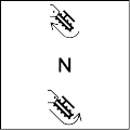
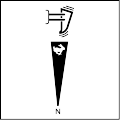
Neutral status indicator
|
Indicates when ground drive and plow control are in neutral.
|
|
|
Cold start wait indicator
|
Lights when cold start aids are active.
Note: Wait until the light turns off before starting the engine.
|
|
|
Operator presence indicator
|
Lights when the operator is in the seat.
Note: Part of the start the interlock system.
|
|
|
Parking brake indicator
|
Lights when the parking brake is engaged.
|
|
|
Engine crank indicator
|
Lights when the engine crank is engaged.
|
|
|
NOx control system indicator
|
Contact your Authorized Service Dealer.
|
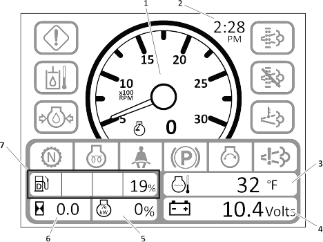
Gauges
G400645
-
Tachometer
-
Clock
-
Engine coolant temperature gauge
-
Voltmeter
-
Engine load percentage
-
Hourmeter
-
Fuel gauge
Gauges Descriptions
| |
Tachometer
|
Displays the engine speed.
|
| |
Clock
|
Displays the time.
|
|
|
Engine coolant temperature gauge
|
Displays the engine coolant temperature.
|
|
|
Voltmeter
|
Displays the machine voltage.
|
|
|
Engine load percentage
|
Displays engine load percentage.
|
|
|
Hour meter
|
Displays the number of hours the engine has been running.
|
|
|
Fuel gauge
|
Displays the fuel level.
|
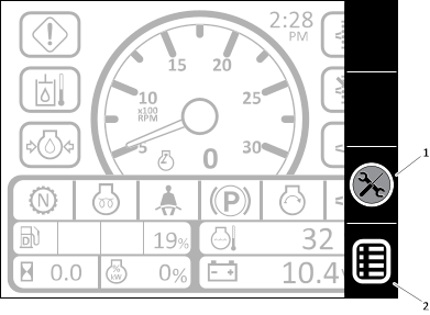
Keys
G40064
-
Hide/Recall diagnostics key
-
Main menu key
Keys Descriptions
|
|
Hide/Recall diagnostics key
|
To hide a diagnostic message, press twice.
To recall, press once.
|
|
|
Main menu key
|
To select the main menu, press.
|
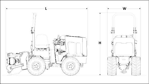
Specifications
Note: Specifications and design are subject to change without notice.
|
Width (with 23 inch tires in the narrow configuration)
|
92.7 cm (36.5 inches)
|
|
Width (with 23 inch tires in the wide configuration)
|
119 cm (47 inches)
|
|
Width (with 26 inch tires in the narrow configuration)
|
103.6 cm (40.8 inches)
|
|
Width (with 26 inch tires in the wide configuration)
|
118.6 cm (46.7 inches)
|
|
Width (with 23 inch dual tires)
|
147 cm (58 inches)
|
|
Width (with 26 inch dual tires)
|
167.6 cm (66 inches)
|
|
Length
|
300 cm (118 inches)
|
|
Height (with 23 inch tires and folded roll bar)
|
167 cm (65.7 inches)
|
|
Height (with 23 inch tires and roll bar in operating position)
|
217.2 cm (85.5 inches)
|
|
Height (with 26 inch tires and folded roll bar)
|
170.7 cm (67.2 inches)
|
|
Height (with 26 inch tires and roll bar in operating position)
|
221 cm (87 inches)
|
|
Weight (with plow, hydra borer, and 26 inch tires)
|
1,439 kg (3,172 lb)
|
|
Wheelbase
|
122 cm (48 inches)
|
|
Minimum turning radius (outside, with 23 inch tires standard configuration)
|
297.2 cm (117 inches)
|
|
Minimum turning radius (inside, with 23 inch tires standard configuration)
|
177.8 cm (70 inches)
|
|
Minimum turning radius (outside, with 63 inch tires standard configuration)
|
287 cm (113 inches)
|
|
Minimum turning radius (inside, with 26 inch tires standard configuration)
|
169.5 cm (66.75 inches)
|
Trencher Specifications
Note: Specifications and design are subject to change without notice.
|
Trench width, max
|
15.2 mm (6 inches)
|
|
Trench depth
|
60.96 or 91.4 mm (24 or 36 inches)
|
|
Offset
|
18.8 cm (7.4 inches)
|
Hydra Borer Sepecifications
Note: Specifications and design are subject to change without notice.
|
Max Torque
|
464 N•m (342 ft-lb)
|
Attachments/Accessories
A selection of Toro approved attachments and accessories is available for use with the machine to enhance and expand its capabilities. Contact
your Authorized Service Dealer or authorized Toro distributor or go to www.Toro.com for a list of all approved attachments and accessories.
To ensure optimum performance and continued safety certification of the machine, use only genuine Toro replacement parts and accessories.
Hauling the Machine
Use a heavy-duty trailer or truck to haul the machine. Use a full-width ramp. Ensure that the trailer or truck has all the
necessary brakes, lighting, and marking as required by law. Please carefully read all the safety instructions. Knowing this
information could help you or bystanders avoid injury. Refer to your local ordinances for trailer and tie-down requirements.
 |
Warning |
 |
Driving on the street or roadway without turn signals, lights, reflective markings, or a slow-moving-vehicle emblem is dangerous
and can lead to accidents causing personal injury.
Do not drive the machine on a public street or roadway.
Trailer Requirements
 |
Warning |
 |
Loading a machine onto a trailer or truck increases the possibility of tip-over and could cause serious injury or death.
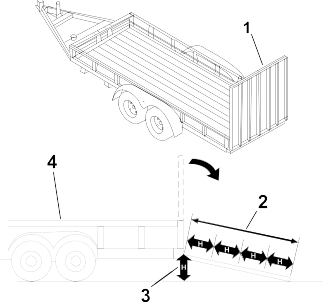
- Use only a full-width ramp; do not use individual ramps for each side of the machine.
- Ensure that the length of ramp is at least 4 times as long as the height of the trailer or truck bed to the ground.
G229507s
- Full-width ramp in stowed position
- Ramp is at least 4 times as long as the height of the trailer or truck bed to the ground
- H = height of the trailer or truck bed to the ground
- Trailer
Loading the Machine
 |
Warning |
 |
Loading a machine onto a trailer or truck increases the possibility of tip-over and could cause serious injury or death.
- Use extreme caution when operating a machine on a ramp.
- Load and unload the machine with the heavy end up the ramp.
- Avoid sudden acceleration or deceleration while driving the machine on a ramp as this could cause a loss of control or a tip-over
situation.
 |
Warning |
 |
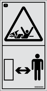
Crushing weight could cause death or serious injury. Stay away.
To help avoid injury:
- Load the machine with the engine at low throttle and the boom as low as possible.
- Load the trailer on level ground.
- Load the trailer correctly to avoid the trailer swaying.
- Attach the trailer to the vehicle before loading or unloading.
- 10 to 15 percent of the total vehicle weight (equipment plus trailer) must be on the tongue to help prevent the trailer from
swaying.
-
Connect the trailer to the towing vehicle and connect the safety chains.
-
If applicable, connect the trailer brakes.
-
Lower the ramp.
-
Start the engine.
-
Raise the trencher boom, if attached, but keep it low.
-
Fully raise or remove the plow blade and ensure that the plow swing lock is engaged.
-
Disengage the parking brake.
-
Slowly drive the machine onto the trailer.
-
Position the machine on the trailer deck for proper weight distribution.
-
Engage the parking brake.
-
Lower the attachments to the trailer bed and turn the machine off.
-
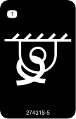
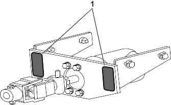
Attach chains to the machine and attachments at the tie down points, where the tie down decals are located.
Tie-Down Points
Tie-down points are identified by the tie-down decals. Securing the machine to the trailer at other points is unsafe and can
damage the machine.
Tying Down the Machine
Use minimum Grade 7, 18.7cm (3/8 inch) transport chain to secure the machine to the trailer.
Loop a transport chain around each tiedown point. See the chart below for the correct distances between tiedown ends. Ensure
that the tiedowns are tight before transporting.
|
Distance
|
Metric
|
US
|
|
A
|
45.7 to 76.2 cm
|
18 to 30 inches
|
Unloading the Machine
 |
Warning |
 |
Crushing weight could cause death or serious injury. Stay away.
To help avoid injury:
- Unload the unit with the engine in low idle and the boom as low as possible.
- Unload the trailer on level ground.
- Attach the trailer to the vehicle before loading or unloading.
-
Lower the trailer ramp.
-
Remove the chains from the tie-down points.
-
Start the machine.
-
Raise the trencher boom, if attached, but keep it low.
-
Fully raise the plow blade and ensure that the plow swing lock is engaged.
-
Disengage the parking brake.
-
Slowly back the machine down the trailer or ramps.
Retrieving the Machine
Under normal conditions, do not tow the machine. If the machine becomes disabled and retrieval is needed:
- Do not tow the machine for more than 180 m (200 yd).
- Tow the machine at less than 1.5–3.0 km/h (1–2 mph).
- You cannot steer the machine as it is towed.
- Use a maximum towing force of 1.5 times the machine weight.
-
Engage parking brake.
-
Block front and rear tires.
-
Drive the towing vehicle to the front of the machine.
-
Attach the machine to the towing vehicle using the tie down points.
-
Ensure that all controls are in Neutral.
-
Open the bypass valve.
-
Move the driving control in the direction of travel.
-
Disengage the parking brake.
-
After towing:
-
Move the controls to Neutral.
-
Engage the parking brake.
-
Block the wheels.
-
Disconnect the machine from the towing vehicle.
-
Turn bypass valve to original position.
Maintenance Safety
- Making unauthorized modifications to the machine may result in it no longer meeting safety standards and regulations and/or
not functioning properly. Allow only competent and trained personnel to modify the machine according to the applicable standards,
regulations, and machine design functionality and requirements.
- Replace the ROPS if it has been modified, damaged, or in a rollover accident.
- Do not allow untrained personnel to service the machine.
- Park the machine on a level surface, disengage the auxiliary hydraulics, lower the attachments, engage the parking brake (if
equipped), shut off the engine, and remove the key. Wait for all movement to stop and allow the machine to cool before adjusting,
cleaning, storing, or repairing it.
- Refer to the US Occupational Safety and Health Administration (OSHA) guidelines for appropriate lockout-tagout procedures.
- Keep your hands and feet away from the moving parts. If possible, do not make adjustments with the engine running.
- Do not tamper with the safety devices.
- Clean up oil or fuel spills.
- Carefully release pressure from components with stored energy.
- Use jack stands to support raised components when required.
- If welding is required, see your Authorized Service Dealer.
Recommended Maintenance Schedule
|
After the first 10 hours
|
|
|
After the first 50 hours
|
|
|
|
|
|
|
After the first 250 hours
|
|
|
Before each use or daily
|
|
|
|
|
|
|
|
|
|
|
|
|
|
|
|
|
|
|
|
|
|
|
Every 10 hours
|
|
|
|
|
|
|
|
|
Every 25 hours
|
|
|
|
|
Every 50 hours
|
|
|
|
|
|
|
|
|
Every 250 hours
|
Checking the Air Filter
|
|
|
|
|
|
|
|
|
|
|
|
Every 300 hours
|
|
|
Every 500 hours
|
|
|
|
|
|
|
|
|
|
|
|
|
|
| |
|
|
|
|
|
Every 1,000 hours
|
|
|
|
|
|
|
|
|
Every 2,000 hours
|
|
|
|
|
Yearly or before storage
|
|
|
|
|
|
|
|
Lubrication
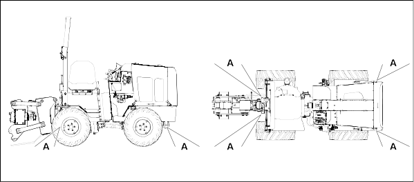
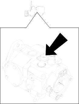
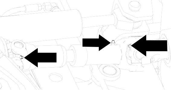
Greasing the Drive Shaft and U-Joint
Grease Type: General purpose grease.
-
Clean the grease fittings with a rag.
-
Pump grease into the fittings until grease begins to ooze out of the bearings (approximately 3 pumps).
-
Wipe up any excess grease.
Greasing the Plow
Grease Type: General purpose grease.
-
Clean the grease fittings with a rag.
-
Pump grease into the fittings until grease begins to ooze out of the bearings (approximately 3 pumps).
-
Wipe up any excess grease.
Engine Maintenance
Engine Safety
- Shut off the engine before checking the oil or adding oil to the crankcase.
- Do not change the engine governor setting or overspeed the engine.
- Keep your hands, feet, face, clothing, and other body parts away from the muffler and other hot surfaces.
Engine Oil Specifications
Note: Specifications and design are subject to change without notice.
|
Crankcase capacity
|
5.2 L (5.5 qt)
|
|
Oil Type
|
Detergent diesel engine oil (meeting or exceeding API service classification CJ-4)
|
|
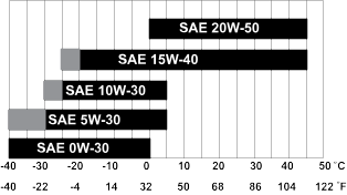
Viscosity
|
See the oil viscosity chart
|
Checking the Engine Oil
-
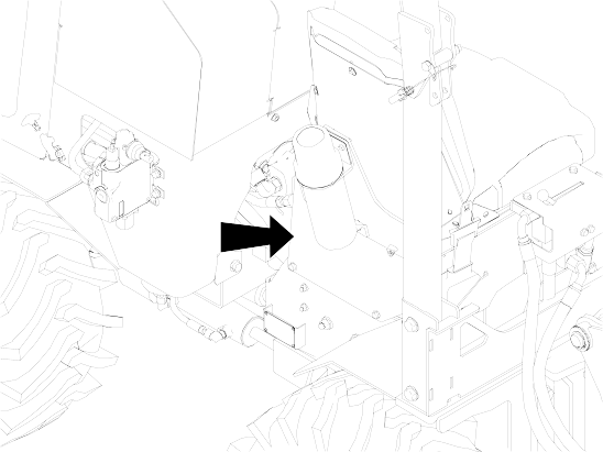
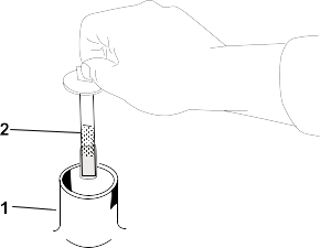
While the oil is warm, check the level at the dipstick  .
.
-
Add oil at the fill point  as needed to keep the level at the highest line on the dipstick.
Changing the Engine Oil
-
While the oil is warm, remove the plug  to drain.
-
Install the drain plug.
-
Replace the filter  each time you change the oil.
-
Add oil at the fill point  .
.
-
Start the engine to circulate the oil.
-
Check the oil level.
Checking the Exhaust Clamp
-
Check the clamp and lock screw on the exhaust extension to ensure that it is tight.
Checking the Exhaust System
-
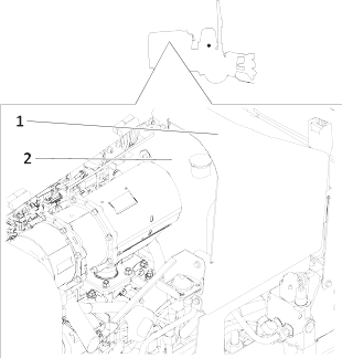
Check for any loose or damaged components. Check the heat shields near the battery, starter, and air cleaner and replace them
if they are damaged.
Fuel System Maintenance
Checking the Fuel Lines
-
Check the fuel lines and connections for any signs of deterioration, damages, leaks, or loose connections. Tighten any loose
connections and contact your Authorized Service Dealer for assistance in fixing damaged fuel lines.
Changing the Fuel Filter
-
Clean the filter head and the outside of the fuel filter.
-
Turn the filter counterclockwise and remove the filter from the filter head.
-
Lubricate the gasket on the new filter canister with clean oil.
-
Install the filter canister by hand until the gasket contacts the filter head, then rotate it an additional 1/2 turn.
-
Start the machine and check for leaks.
Draining the Fuel/Water Separator
-
Place a container under the fuel filter.
-
Loosen the filter canister drain valve.
-
After the water has drained, tighten the drain valve.
Electrical System Maintenance
Electrical System Safety
- Disconnect the battery before repairing the machine. Disconnect the negative terminal first and the positive last. Connect
the positive terminal first and the negative last.
- Charge the battery in an open, well-ventilated area, away from sparks and flames. Unplug the charger before connecting or
disconnecting the battery. Wear protective clothing and use insulated tools.
 |
Warning |
 |
Battery acid is corrosive; contacting it can cause death or serious injury.
To avoid injury, do the following:
- Avoid contact with skin, eyes, and clothing. Wear appropriate gloves and eye protection.
- Never attempt to charge a battery that is leaking, bulging, heavily corroded, frozen, or otherwise damaged.
- Refer to the safety data sheet (SDS) for additional battery information.
 |
Warning |
 |
Fire or explosion from explosive hydrogen gas can cause death or serious injury. Keep heat, flames, sparks, and other sources
of ignition away.
To help avoid injury:
- Use a single 12 V maximum source for charging. Never connect the battery to rapid chargers or dual batteries.
- Never lean over the battery when making connections.
- Never allow the vehicles to touch each other when charging.
- Never short-circuit the battery terminals or strike the battery posts or cable terminals.
- Refer to the safety data sheet (SDS) for additional battery information.
Checking the Battery
-
Turn off the machine and remove the key.
-
Turn battery disconnect switch off.
-
Ensure that there are no ignition sources near the battery.
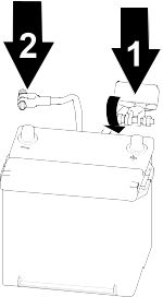
-
Loosen and remove the battery cable clamps carefully, negative (-) cable first.
-
Clean the cable clamps and terminals.
-
Check for any signs of corrosion and clean as needed.
-
Connect the battery cable clamps, positive (+) cable first.
-
Tighten any loose connections.
Charging the Battery
 |
Warning |
 |
Charging the battery produces gasses that can explode.
Never smoke near the battery and keep sparks and flames away from battery.
-
Disconnect the machine controller.
-
Inspect the battery for signs of cracking, bulging, leaking, or other damage.
-
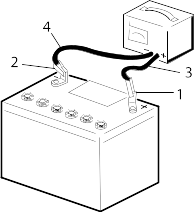
Connect the red positive (+) jumper cable clamp to the positive (+) post  of the battery in the disabled machine.
-
Connect the other red positive (+) jumper cable clamp to the positive (+) post of battery in the service vehicle.
-
Connect the black negative (-) cable clamp to the negative (-) post of battery  in the service vehicle.
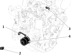
-
Connect the other black negative (-) cable clamp to the engine or frame ground on the disabled vehicle, at least 31 cm (12
inches) from the failed battery.
-
Charge the battery for 1 hour at 25 to 30 A or 6 hours at 4 to 6 A.
Do not overcharge the battery.
G003792S
- Positive battery post
- Negative battery post
- Red (+) charger lead
- Black (-) charger lead
-
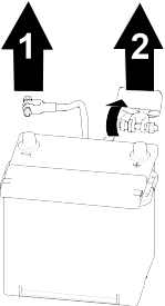
Remove the jumper cables from the service vehicle, black negative (-) clamp first. Do not allow the clamps to touch.
-
Remove the black negative (-) cable clamp  from the disabled machine or frame ground.
-
Remove the red positive (+) cable clamp  from the disabled machine.
-
Turn the battery disconnect to On.
Drive System Maintenance
Tire Specifications
|
Torque (in a crossing pattern)
|
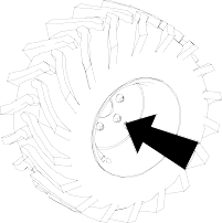
108 to 135 N•m (80 to 100 ft-lbs)
|
|
23 x 10.5 x 12
|
4
|
138
|
20
|
|
26 x 12 x 12
|
8
|
207
|
42
|
Note: Use a lower tire pressure when operating in sandy soil conditions to provide better traction in the loose soil.
|
Changing the Axle Oil
-
Place a drain pan under the pinion housing of the axle.
-
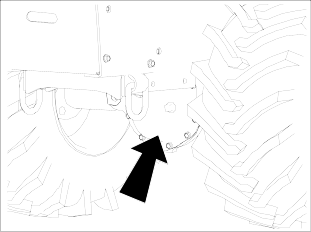
Remove the bolts securing the cover, and remove the cover and gasket.
-
Clean the surfaces.
-
Install a new gasket.
-
Install the cover and drain plug.
-
Remove the fill plug.
-
Add differential oil until the oil is level with the bottom of the fill plug hole.
-
Install the fill plug.
-
Repeat with the other differential.
Gearbox Specifications
|
Transmission oil
|
SAE 80W90 limited slip oil
|
|
Capacity
|
0.47 L (0.5 qt)
|
|
Axle oil
|
SAE 80W90 API classification level GL5
|
|
Front axle capacity
|
2.4 L (2.5 US qt)
|
|
Rear axle capacity
|
2.4 L (2.5 US qt)
|
Checking the Gearbox Oil
-
Open the gearbox oil cap/plug and check the oil level.
-
Add fluid as needed to keep the level at the bottom of the fill plug.
Changing the Gearbox Oil
-
While the oil is warm, remove the plug  and drain the tank.
-
Install the plug.
-
Replace the filter each time the oil is changed.
-
Add fluid at the fill point  until the oil level is even with the bottom of the fill plug.
Cooling System Maintenance
Cooling System Safety
- Swallowing engine coolant can cause poisoning; keep out of reach from children and pets.
- Discharge of hot, pressurized coolant or touching a hot radiator and surrounding parts can cause severe burns. If you must
work on or near the radiator, allow it to cool or wear gloves.
- Always allow the engine to cool at least 15 minutes before removing the radiator cap.
- Use a rag when opening the radiator cap, and open the cap slowly to allow steam to escape.
Coolant Specifications
Note: Specifications and design are subject to change without notice.
|
Coolant Specification
|
a mixture of 50% ethylene glycol and 50% water
|
|
Engine and Radiator Coolant Capacity
|
10.2 L (10.8 qt)
|
Checking the Engine Coolant Level
Note: Do not use only water or alcohol/methanol based coolants. Use a mixture.
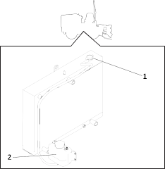
-
Remove the radiator  and expansion tank
 caps.
caps.
-
Check the coolant level in the radiator.
Note: Fill the radiator to the top of the filler neck and the expansion tank to the full mark.
-
If the coolant is low, add the mixture to the full mark.
-
Install the radiator cap and expansion tank cap.
Changing the Engine Coolant
-
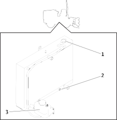
Remove the radiator  and expansion tank
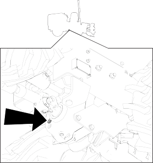
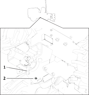
  caps and drain plug
  .
.
-
After the fluid has drained, install the drain plug.
-
Add the coolant mixture at the cap to keep the level at the top of the filler neck and the expansion tank.
Note: Fill the radiator to the top of the filler neck and the expansion tank to the full mark.
-
Install the cap.
Checking the Radiator Hoses
-
Check the radiator hoses for leaks, abnormal swelling, or other signs of deterioration. Check for leaks or corrosion at the
water pump and fittings.
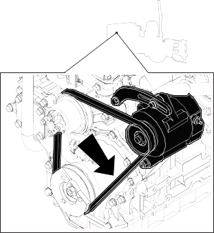
Belt Maintenance
Checking the Drive Belt Tension
The belt is properly tensioned when it moves about 7–10 mm (1/4–3/8 inch) when you push it at the long span.
-
Check the belt for excessive slack, damage, or wear.
Adjusting the Drive Belt
-
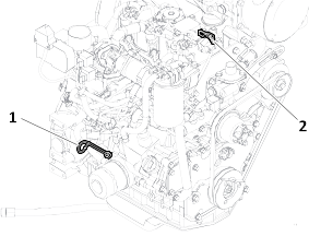
Loosen the pivot and 2 alternator bolts.
-
Adjust the alternator position as needed.
-
Check the belt tension.
-
Tighten the pivot and alternator bolts.
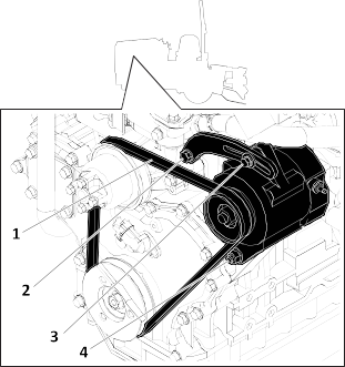
Replacing the Drive Belt
-
Loosen the four alternator bolts 

 .
.
-
Replace the fan belt  .
.
-
Adjust the belt tension as needed.
-
Tighten the bolts.
-
Check the tension.
Controls Maintenance
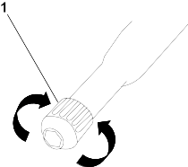
Adjusting the Parking Brake
-
Shut off the engine.
-
Disengage the parking brake.
-
Rotate the knob  to adjust the parking brake.
- Counterclockwise—loosen
- Clockwise—tighten
Note: Rotate the knob no more than 1 revolution each time.
-
Test the parking brake.
-
Repeat steps above until the machine does not move forward when the parking brake is engaged.
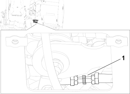
Adjusting the Neutral Position
If the machine moves in any direction when you release the traction control lever, adjust the traction drive neutral position.
-
Lower all attachments, engage the parking brake, shut off the machine, and block the tires.
-
Loosen the jam nuts on each end of the traction rod.
-
Adjust the adjustment nut  depending on which way the machine is moving:
- If the machine is moving forward, turn the nut counter clockwise.
- If the machine is moving rearward, turn the nut clockwise.
-
Tighten the jam nuts on each end of the rod.
-
Test the machine to see if further adjustment is needed.
Cleaning the Controls Linkage Assembly
-
Spray the direction controls linkage assembly with compressed air.
Hydraulic System Maintenance
Hydraulic System Safety
 |
Warning |
 |
Injection from pressurized fluid or air can cause death or serious injury. If you are injured, seek immediate medical attention
from a doctor familiar with this type of injury.
To help avoid injury:
- Before disconnecting a hydraulic line, shut off the engine and operate all the controls to relieve pressure.
- Lower, block, or support any raised component with a hoist.
- Cover the connection with a heavy cloth and loosen the connector nut slightly to relieve residual pressure. Catch all fluid
in a container.
- Before using the system, check that all connections are tight and all lines are undamaged.
- Use a piece of cardboard or wood, rather than hands, to check for leaks.
- Before using the hydraulic system, check that all connections are tight and all lines are undamaged.
- Turn the engine off and operate all controls to relieve pressure from the system before performing work or disconnecting a
hydraulic line.
Hydraulic Fluid Specifications
Note: Specifications and design are subject to change without notice.
|
Hydraulic-Fluid type
|
Toro Premium Transmission/Hydraulic Tractor Fluid
|
|
Hydraulic fluid tank capacity
|
28.6 L (7.6 US gallons)
|
|
Hydraulic fluid system capacity
|
25.8 L (6.8 US gallons)
|
Checking the Hydraulic Fluid Level
-
Remove the cap from the filler neck  and check the fluid level on the dipstick
  .
.
-
Add fluid as needed.
-
Install the cap.
Changing the Hydraulic Fluid
-
Remove the upper left panel of the console  .
.
-
Remove the hydraulic tank cap  and use a pump to empty the hydraulic tank.
-
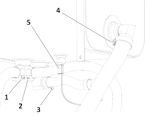
Remove the lower right side cover plate and loosen the hose clamp holding the suction hose to the hydraulic tank  .
.
-
Remove the left side cover plate and loosen the 3 hose clamps under the hydraulic tank 

 .
.
-
Disconnect the electrical lead to the fluid temperature sensor at the bottom of the reservoir  .
.
-
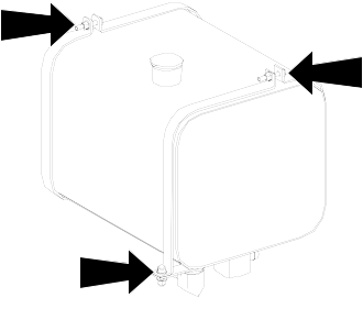
Remove the bolts securing the tank straps.
-
Remove the hydraulic tank.
-
Flush the reservoir with cleaning solvent.
-
Remove the elbow adapters and clean the filter screens with compressed air.
Note: Make a note of the orientation of the adapters.
-
Apply thread sealant to the threads of the suction screen and install the screen, elbow, hose, and clamp.
-
Connect the electrical lead to the fluid temperature sensor.
-
Connect the hose to the tank and secure with the clamps.
-
Install the hydraulic tank assembly.
-
Fill the tank.
-
Install the dipstick cap.
-
Start the engine and allow it to run for a few minutes.
-
Shut off the engine.
-
Check the hydraulic fluid level.
-
Add fluid as needed to keep the level at the line on the dipstick.
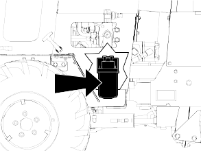
Changing the Hydraulic Filter
-
Lower any attachments, engage the parking brake, shut off the engine, and remove the key.
-
Turn the filter counterclockwise, remove and discard it.
-
Apply a thin coat hydraulic fluid to the rubber gasket on the replacement filter.
-
Fill the filter with clean fluid.
-
Install the replacement filter. Tighten it clockwise until the filter contacts the filter head, then tighten the filter an
additional 3/4 turn.
-
Start the engine and let it run for about 2 minutes.
-
Shut off the engine and check for leaks.
Checking the Hydraulic Lines
-
Check the hydraulic lines for leaks, loose fittings, kinked lines, loose mounting supports, wear, and deterioration. Make
necessary repairs before operating.
Plow Maintenance
Plow Vibrator Oil Specifications
Note: Specifications and design are subject to change without notice.
|
Crankcase capacity
|
237 L (8 oz)
|
|
Oil Type
|
15W40
|
Changing the Plow Vibrator Oil
-
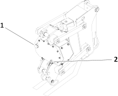
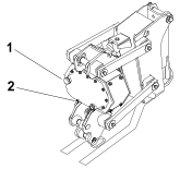
Remove the plug and drain the oil into a suitable container.
-
Install the plug and add fluid at the fill  until the level is at the halfway point on the sight glass.
Checking the Plow Blade
Check the plow blade for wear. Replace it as needed.
Changing the Plow Blade
The plow blades are heavy; use 2 people to complete this procedure.
-
Shut off the engine.
Note: Ensure that the vibratory plow is raised high enough for the blade to be changed.
-
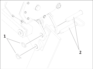
Flip the 2 circular snap rings  over and remove the snap-ring pin.
-
Pull the 2 pins  out of the blade.
-
Place the new blade into the plow blade assembly and secure it with 2 pins and 2 snap-ring pins.
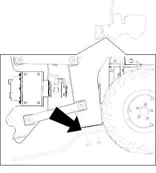
Changing the Plow Skid Shoes
-
Raise the plow about 91 cm (36 inches) off the ground.
-
Shut off the engine and remove the key.
-
Remove the bolts securing the skid shoes to the plow.
-
Install the new skid shoes and secure them with the previously removed hardware.
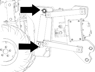
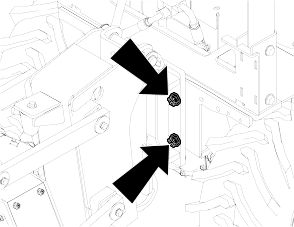
Checking the Plow Mounting Bolts
-
Check the bolts every 10 hours. Tighten as needed.
Trencher Maintenance
Checking Chain Components
-
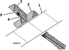
If a rock chain bit is in use, check that the bits rotate freely.
-
Clean the chain and check the bits after each use.
-
Replace the bit when the carbide cap or insert is worn.
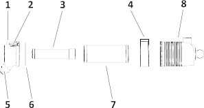
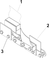
-
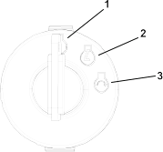
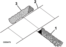
If the sidebars (2) are bent or loose on the chain pins, chain spacers should be used to join the sidebars.
-
Check the pins and bushings for wear by measuring the distance between the chain pins (3) and comparing it with the new chain.
-
Check the teeth (1) for wear.
Note: Replace worn teeth using Toro replacement parts and maintaining the original tooth pattern.
Adjusting the Digging Chain Tension
Check every 10 hours. Adjust as needed.
-
Move the boom into a horizontal position and stop the engine.
-
Set the parking brake.
-
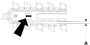
Ensure the distance from the bottom of the boom to the chain (A) measures 38–51 mm (1.5–2 inches).
-
Note: Do not overtighten the chain. Overtightening will cause chain stretch, loss of machine performance, and possible premature
chain failure.
To adjust the tension, loosen the jam nut on the adjustment screw.
-
To tighten the digging chain, turn the adjustment screw clockwise. To loosen it, turn the screw counterclockwise.
-
When the chain is properly tensioned, tighten the jam nut.
Removing the Chain
Replace the sprockets when a new chain is installed.
-
Fasten and adjust the seat belt.
-
Start the engine.
-
Turn the digging chain until the connector pin is on top of the boom.
-
Lower the boom to the ground.
-
Engage the parking brake.
-
Shut off the machine.
-
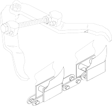
Secure the chain by clamping the links on either side of the connector pin with chain jaws as shown. Squeeze the jaws to reduce
pressure on the pin.
-
Relieve chain tension.
-
Stand clear of the chain and remove the lock key from the connector pin.
-
Drive the connector pin out of the link.
-
Unclamp the links. Slowly release the cable and lower the chain to the ground.
 |
Warning |
 |
Raised component. Crushing can cause death or serious injury. Stay away. Use correct equipment and procedures.
-
Lay the chain on the ground with the teeth down.
Checking the Trencher Mounting Bolts
-
Check the bolts every 10 hours. Tighten them as needed.
Checking the Trench Cleaner Position
[Graphic number is missing]
Check the trench cleaner position (if equipped) every 10 hours or anytime the digging chain is adjusted or replaced.
Ensure there is 76–102 mm (3–4 inches) between the digging teeth and the inside of the trench cleaner shoe (A).
-
ROPS Maintenance
ROPS Notice
The protection offered by the Rollover Protective Structure (ROPS) will be impaired if it has been subjected to any modification,
structural damage, or has been involved in an overturn accident. The ROPS must be replaced after a roll-over.
Do not try to weld or straighten a damaged ROPS bar.
Checking the Roll Bar
-
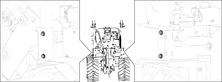
Check the 4 bolts for looseness or wear. Torque the bolts to 203–223 N•m (150–165 ft•lb).
-
Inspect the roll bar for cracks, rust, or holes in the roll bar component parts.
Note: Age, weather, and accidents cause damage to the roll bar and ROPS parts. If you have any doubts about the ROPS system, contact
an Authorized Service Dealer.
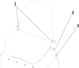
Checking the Seat Belt
-
Check the seat belt 
 for damage and replace any damaged parts.
-
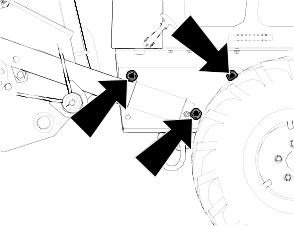
Ensure that the mounting bolts  for the seat belts are tight. Torque the bolts to 104–115 N•m (77–85 ft•lb).
-
Keep the seat belts clean using only soap and water.
Cleaning
Removing Debris
-
Turn the battery disconnect to Off.
-
Wipe away debris from the air cleaner.
-
Clean any debris buildup on the engine and in the transmission with a brush or blower.
-
Ensure that all mud and debris is rinsed from the tires before parking the machine overnight.
Do not spray water onto the operator console or the electrical center in the engine compartment. Water can damage electrical
components. Wipe them down instead.
Keep pressurized water away from the ECU connections.
Storage Safety
- Shut off the engine, remove the key (if applicable), wait for all moving parts to stop, and allow the machine to cool before
storing it.
- Do not store the machine or fuel near flames.
Preparing the Machine for Storage Over 30 Days
-
Clean the machine.
-
Grease the machine.
-
Before long term storage, wash the attachment with mild detergent and water to remove dirt and grime.
-
Check the condition of the hydraulic hoses. Replace any damaged hoses.
-
Ensure that all hydraulic couplers are connected together to prevent contamination of the hydraulic system.
-
Prepare the engine.
-
Service the air cleaner.
-
Change the engine oil.
-
Check and tighten all fasteners. Repair or replace any worn, damaged, or missing parts.
-
Paint all scratched or bare metal surfaces with paint available from your Authorized Service Dealer.
-
Store the machine in a clean, dry garage or storage area. Remove the key from the ignition switch and keep it in a memorable
place.
-
Cover the machine to protect it and keep it clean.
Decommission the Machine
Before decommissioning the machine, follow local regulations for disposing of hazardous substances. For more information on
draining fluids, see the Maintenance chapter or contact your Authorized Service Dealer.

