The hand spray wand kit is an attachment for a turf spray application vehicle and is intended to be used by professional, hired operators in commercial applications. It is primarily designed for spraying on well-maintained lawns in parks, golf courses, sports fields, and on commercial grounds.
You may contact Toro directly at www.Toro.com for product safety and operation training materials, accessory information, help finding a dealer, or to register your product.
Setup
Preparing the Machine
-
Ensure that the machine is empty of all fluids. If chemicals have been used in the machine, flush the system thoroughly with clean water and drain the water; refer to your vehicle Operator’s Manual for instructions.
-
Disconnect the negative battery terminal from the battery.
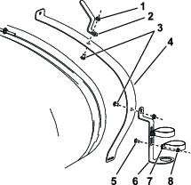
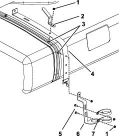
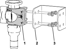
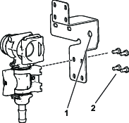
Installing the Hose Hook and Spray-Gun Bracket
Parts needed for this procedure:
| Hose hook | 1 |
| Flanged locknut (3/8 inch) | 4 |
| Flanged locknut (5/16 inch) | 4 |
| Carriage bolt (3/8 x 3/4 inch) | 4 |
| Carriage bolt (5/16 x 1 inch) | 4 |
| R-clamp | 2 |
| Spray-gun bracket | 1 |
Installing the Shutoff Valve (Multi Pro 1750 with and without GeoLink and Multi Pro WM Only)
Parts needed for this procedure:
| Female cap | 2 |
| Shutoff valve | 2 |
Installing the Shutoff Valve (Multi Pro 1750 without GeoLink and Multi Pro WM Only)
-
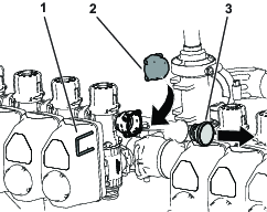
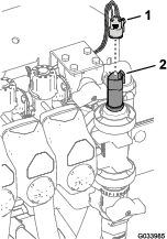
Remove the retainer that secures the a actuator to the manifold valve for the section valve or agitation valve.
Note: Squeeze the 2 legs of the retainer together while pushing it down.
Note: Retain the actuator and retainer.
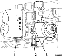
-
Remove the actuator from the manifold valve.
-
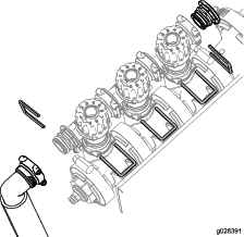
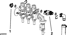
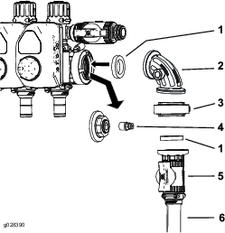
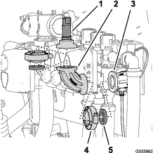
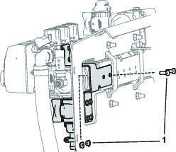
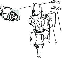
Remove the retainers holding the bypass adjustment assembly, end cap, and the fitting and hose assembly as shown in Figure 4.
Note: You will not use the end cap, but keep the O-ring on the cap.
-
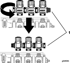
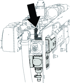
Rotate the bypass adjustment assembly 180 degrees as shown in Figure 5.
-
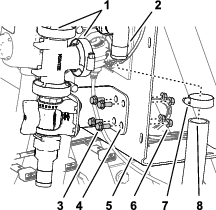
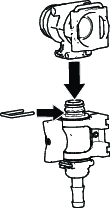
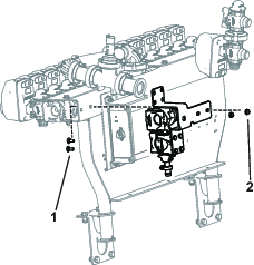
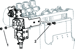
Install the bypass-adjustment assembly, female cap, O-rings, shutoff valve, and fitting and hose assembly using the retainers previously removed as shown in Figure 6.
Installing the Shutoff Valve for Multi Pro 1750 with GeoLink
-
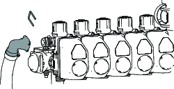
Remove the end cap on the end of the manifold and replace it with a female cap. Secure the cap with the retainer.
-
Remove the retainer securing the hose to the end of the manifold.
-
Install the shutoff valve on the hose and machine. Secure it with the retainers.
Installing the Control Valve for the Spray Gun
Parts needed for this procedure:
| Refer to the Parts Table | 0 |
Parts Table
| Part | 5800 | 1750 | Workman | |||||
|---|---|---|---|---|---|---|---|---|
| Qty | 2023 and Before | 2024 and After without GeoLink | 2024 and After with GeoLink | 2023 and Before | 2024 and After without GeoLink | 2024 and After with GeoLink | 2023 and Before | 2024 and After |
| Control valve | 1 | 1 | 1 | 1 | 1 | |||
| Control valve (with flange end cap) | 1 | 1 | 1 | |||||
| Control valve wing handle | 1 | 1 | 1 | 1 | 1 | 1 | 1 | 1 |
| Straight fitting | 1 | 1 | 1 | 1 | 1 | 1 | 1 | 1 |
| Valve mount | 1 | 1 | 1 | 2 | 2 | 2 | ||
| Control valve bracket (2023) | 1 | |||||||
| Control valve bracket (with hole) | 1 | 1 | ||||||
| Control valve bracket (no hole) | 1 | 1 | 1 | |||||
| Shutoff valve | 1 | 1 | 2 | 1 | 1 | |||
| 90-degree elbow fitting | 1 | 1 | ||||||
| T-fitting | 1 | |||||||
| Manifold tee | 1 | 1 | 1 | 1 | ||||
| Gasket clamp | 1 | 1 | 1 | |||||
| Bolt (M6 x 12 mm) | 4 | 8 | 4 | 8 | 8 | 8 | ||
| Carriage bolt (1/4-20 X 5/8 inch) | 2 | 2 | ||||||
| Hex head bolt (1/4-20 X 5/8 inch) | 4 | 2 | 2 | |||||
| Locknut (1/4 inch) | 4 | 2 | 2 | 2 | 2 | |||
Assembling the Control Valve (Multi Pro 1750—2023 and Before and Multi Pro WM—2023 and Before)
-
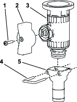
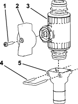
Assemble the green wing handle and straight fitting to the control valve.
-
Remove the flange clamp that secures the end cap and coupler at the pressure-gauge port.
-
Remove the coupler from the end cap.
-
Install the control valve assembly.
-
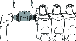
Install the coupler into the open port on the 90-degree fitting.
Note: The port in the side of the 90-degree fitting for the Multi Pro 1750 and Multi Pro WM is at the forward side (not shown) of the fitting.
-
Connect the hose-reel supply hose to the control valve using a hose clamp.
Removing the Control Valve from the Machine (Multi Pro 5800—2023 and Before)
-
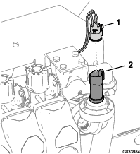
Disconnect the 3-socket connector for the pressure transducer.
-
Remove the flange clamp that secures the pressure transducer to the 90° fitting, and remove the transducer, gasket and flange clamp.
-
Remove the flange clamp that secures 90° fitting to the 90° fitting with a connector for the sense tube, and remove the 90° fitting, gasket and flange clamp.
Preparing the Control Valve (Multi Pro 5800—2023 and Before)
-
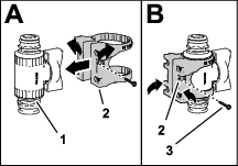
Assemble the valve mount onto the control valve as shown in A of Figure 14.

-
Secure the valve mount to the control valve with the flange-head screw (#6), and tighten the screw by hand (B of Figure 14).
-
Assemble the valve mount to the control-valve bracket with the 4 bolts (6 x 12 mm) and 4 flat washers; torque the bolts to 10 to 12 N∙m (86 to 106 in-lb).
-
Align the flange of the T-fitting to the flange of the control valve.

-
Loosely attach the T-fitting to the control valve with a gasket and flange clamp.
-
Align the flange of the pressure transducer with the flange of the T-fitting.

-
Assemble the pressure transducer to the T-fitting with a gasket and flange clamp, and tighten the clamp by hand (Figure 17).
Drilling the Manifold Mount (Multi Pro 5800—2023 and Before)
-
Align the flange of the T-fitting with the flange of the 90° fitting with a connector for the sense tube.

-
Loosely assemble the T-fitting and the 90° fitting with a gasket and a flange clamp.
Note: Rotate the control-valve bracket as necessary to align it flush with the surface of the valve mount.
-
Using the control-valve bracket as a template, mark the location of the holes in the bracket onto the surface of the manifold mount.

-
Remove the clamp, gasket, T-fitting with the flange from the 90° fitting with a connector for the sense tube.
-
Center punch the marks on the manifold mount that you made in step 3.
-
Drill 4 holes 6 mm (1/4 inch) into the manifold mount at the centerpunch marks that you made in step 5.

Assembling the Control Valve (Multi Pro 5800—2023 and Before)
-
Align the flange of the T-fitting with the flange of the 90° fitting with a connector for the sense tube.
-
Loosely assemble the T-fitting and the 90° fitting with a gasket and a flange clamp.
-
Assemble the control-valve bracket to the manifold mount with 4 hex head bolts (1/4 x 5/8 inch) and 4 flange locknut (6 mm); torque the bolts to 10 to 12 N∙m (86 to 106 in-lb).
-
Tighten by hand the flange clamp that secures the control valve and the T-fitting and the flange clamp that secures T-fitting to the 90° fitting with a connector for the sense tube.
-
Connect the 3-socket connector for the pressure transducer.
Assembling the Control Valve (All Multi Pro Machines—2024 and After)
Installing the Control Valve Assembly (Multi Pro 5800—2024 and After)
-
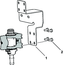
Secure the control valve assembly to the bracket using 4 bolts (M6)
-
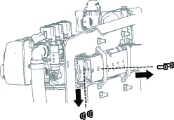
Remove the existing hardware as shown in Figure 26.
-
Secure the bracket to the machine using existing hardware.
-
Secure the top of the bracket using 4 bolts (M6).
Installing the Manifold T-Fitting on the Control Valve Assembly (Multi Pro 1750 with and without GeoLink, Multi Pro WM, and Multi Pro 5800 with GeoLink—2024 and After)
-
Install the manifold T-fitting assembly onto the control valve.
-
Secure the assembly onto the bracket using 4 bolts (M6).
Installing the Shutoff Valve Assembly (Multi Pro 1750 with and without Geolink and Multi Pro WM—2024 and After)
Assemble the valve mount onto the shutoff valve and secure it to the bracket using 4 bolts (M6).
Installing the Bracket Assembly (Multi Pro 5800 with GeoLink and Multi Pro 1750 with GeoLink—2024 and After)
Installing the Control Valve Assembly (Multi Pro 1750 and Multi Pro WM—2024 and After)
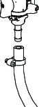
Connecting the Spray Hose
Parts needed for this procedure:
| Spray gun assembly | 1 |
| Straight barbed fitting | 1 |
| Hose clamp | 2 |
| Hose | 1 |
Note: Use PTFE tape to seal tapered pipe thread fittings.
-
Secure the straight barbed fitting to the open end of the hose-reel supply hose with a hose clamp.
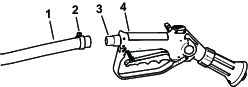
-
Secure the end of the hose on the control valve with a hose clamp.
-
Wrap the excess hose around the hook on the tank, and store the spray gun in the bracket.
-
Connect the negative battery wire to the battery.
-
Calibrate the bypass adjustment assembly; refer to your machine Operator’s Manual.
Operation
Warning
Fluid under pressure can penetrate skin and cause injury.
-
Keep your body and hands away from nozzles that eject fluid that is under high pressure.
-
Do not aim the sprayer at any person or animal.
-
Ensure that all fluid hoses and lines are in good condition and all connections and fittings are tight before applying pressure to the system.
-
Use cardboard or paper to find leaks.
-
Safely relieve all pressure in the system before performing any work on it.
-
Get immediate medical help if fluid is injected into the skin.
-
Hot liquids and chemicals can cause burns or other harm.
Turf Care Precautions while Operating in Stationary Modes
Important: Under some conditions, heat from the engine, radiator, and muffler can potentially damage the grass when operating the sprayer in a stationary mode. Stationary modes include tank agitation, hand spraying, or using a walking boom.
Use the following precautions:
-
Avoid stationary spraying when conditions are very hot and/or dry, as turf can be more stressed during these periods.
-
Avoid parking on the turf while stationary spraying. Park on a cart path whenever possible.
-
Minimize the amount of time the machine is left running over any particular area of turf. Both time and temperature affect how much the grass may be damaged.
-
Set the engine speed as low as possible to achieve the desired pressure and flow. This will minimize the heat generated and the air velocity from the cooling fan.
-
Allow heat to escape upward from the engine compartment by raising the engine guard/seat assemblies during stationary operation rather than being forced out under the vehicle. Refer to your Operator’s Manual for more information on raising the seat assemblies.
Note: Use a heat shield blanket underneath the vehicle during stationary operation if you desire additional heat protection. Contact an Authorized Toro Dealer to obtain a Toro heat shield blanket kit for turf sprayers.
Switching from Boom Spray Mode to Hand Spray Mode
-
Stop the machine, turn the booms off, and set the parking brake.
Warning
Driving while using the hand sprayer can cause loss of control, resulting in injury or death. Do not operate the hand sprayer while driving.
-
At the back of the machine, ensure that the trigger lock on the spray gun is locked.
-
Rotate the green handle on the control valve 90 degrees.
-
At the operator's position, turn the pump on.
-
Switch the master boom to the ON position.
-
Set the engine to the desired speed, then engage the neutral engine speed lock.
Important: Do not use a pressure setting higher than 1034 kPa (150 psi) with the hand sprayer.
Switching from Hand Spray Mode to Boom Spray Mode
-
Rotate the green handle on the control valve 90 degrees..
-
Direct the spray gun nozzle at an area where it is safe to spray, release the trigger lock, and pull the trigger until all remaining fluid is out of the hose, then set the trigger lock.
-
Return the spray gun to the holder.
-
Return the engine to idle speed.
-
Stop the pump.
Important: Ensure that you flush the spray gun with fresh clean water during your daily cleaning routine (refer to your sprayer Operator's Manual). Failure to properly clean the spray gun may degrade the performance and reliability of the spray gun.
-
Use the rate switch to set the desired spray pressure.