Introduction
The Electric Hose Reel Kit is a dedicated attachment for a turf spray application vehicle and is intended to be used by professional, hired operators in commercial applications. It is primarily designed for spraying on well-maintained lawns in parks, golf courses, sports fields, and on commercial grounds
Read this information carefully to learn how to operate and maintain your product properly and to avoid injury and product damage. You are responsible for operating the product properly and safely.
Visit www.Toro.com for more information, including safety tips, training materials, accessory information, help finding a dealer, or to register your product.
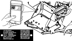
Whenever you need service, genuine Toro parts, or additional information, contact an Authorized Service Dealer or Toro Customer Service and have the model and serial numbers of your product ready. Figure 1 identifies the location of the model and serial numbers on the product. Write the numbers in the space provided.
Important: With your mobile device, you can scan the QR code on the serial number decal (if equipped) to access warranty, parts, and other product information.
Note: This product complies with all relevant European directives. For details, please see the Declaration of Incorporation (DOI) at the back of this publication.Determine the left and right sides of the machine from the normal operating position.
Important: Teflon tape is required for the installation of this kit. The tape is used to wrap threads of fittings before assembly. Threads should be wrapped starting at the base and traveling to the tip of fitting to ensure a waterproof seal.
Important: A non-petroleum based lubricant, such as vegetable oil, will be required for the installation of this kit.
Safety
Improper use or maintenance by the operator or owner
can result in injury. To reduce the potential for injury, comply with
these safety instructions and always pay attention to the safety-alert
symbol  ,
which means Caution, Warning, or Danger—personal safety instruction.
Failure to comply with the instruction may result in personal injury
or death.
,
which means Caution, Warning, or Danger—personal safety instruction.
Failure to comply with the instruction may result in personal injury
or death.
Read also the safety and operation instructions in the vehicle Operator's Manual.
-
Do not aim the hand sprayer at people or animals. Fluids under high pressure can penetrate skin and cause severe injury, possibly resulting in amputation or death. Hot liquids and chemicals can also cause burns or injury. If any part of the body comes in contact with the spray stream, immediately consult a physician familiar with injected fluid injuries.
-
Do not place your hand or any other part of your body in front of the spray nozzle.
-
Do not leave the equipment under pressure when you are not present.
-
Do not use the hand sprayer if the hose, trigger lock, nozzle, or any other part is damaged or missing.
-
Do not use the hand sprayer if there are any leaks in any hoses, fittings, or other components.
-
Do not spray near power lines.
-
Do not drive while spraying with a hand sprayer.
-
Wear a chemical suit, goggles, respirator, rubber shoes, and protective gloves when spraying chemicals with the hand sprayer.
-
Operate the machine only in good visibility and appropriate weather conditions. Do no operate the machine when there is a risk of lightning.
Caution
Chemicals are hazardous and can cause personal injury.
-
Read the directions on the chemical labels before handling the chemicals and follow all manufacturer recommendations and precautions.
-
Keep chemicals away from your skin. Should contact occur, wash the affected area thoroughly with soap and clean water.
-
Wear goggles and any other protective equipment recommended by the chemical manufacturer.
Installation
Preparing the Machine
-
Empty the sprayer tank.
-
Clean and rinse the sprayer tank; refer to the Operator's Manual for your machine.
-
Park the machine on a level surface, engage the parking brake, shut off the pump, shut off the engine, remove the key, and wait for all moving parts to stop.
-
Disconnect the negative battery cable.
-
Disconnect the positive battery cable.
Installing the Wire Harness
Parts needed for this procedure:
| Wire harness | 1 |
| Switch | 1 |
| Weatherproof cap and nut | 1 |
| Small R-clamp | 1 |
| Flange nut (3/8) | 1 |
| Carriage bolt | 1 |
| Fusible link wire harness (108-9455) | 1 |
| Relay (99-7435) | 1 |
| Push-in fastener | 1 |
Installing the Small R-Clamp
-
Remove the fasteners securing the front tank straps at the top of the tank.
Note: Retain all parts.
-
Install a carriage bolt to the lower inboard hole on the right tank strap.
-
Install the tank strap fasteners removed previously to secure the straps to the tank.
Note: Make sure the strap is secure to the tank. Do not overtighten it.
-
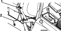
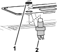
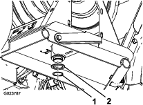
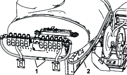
Secure a small R-clamp to the carriage bolt using a flange nut (3/8 inch) as shown in Figure 2.
-
Route the hose reel end of the wire harness through the R-clamp as shown in Figure 2.
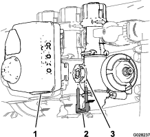
Installing the Switch
-
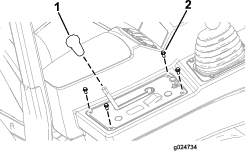
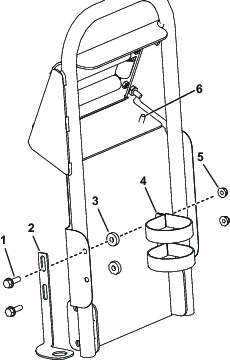
Remove the 4 hex-head screws that secure the control-panel cover to the console, and lift the panel slightly.
Note: If needed, remove the knob from the differential-lock rod.
-
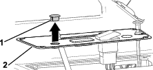
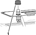
Remove the round plug from the control-panel cover (Figure 4).
-
Assemble the switch to the control-panel cover with the jam nut, and tighten the jam nut by hand (Figure 5).
-
Install the button cover onto the switch (Figure 6).
Connecting the Wire Harness
-
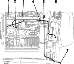
Connect the 2 connectors on the wire harness to the 2-blade connector on the switch (Figure 7).
-
Secure the control-panel cover to the console arm using the previously removed bolts.
Note: Install the knob on the differential-lock rod if you previously removed it.
-
Connect the nearby connector into the hose reel plug on the main wire harness, located under the front portion of the control arm.
-
Plug the next connector into the relay (Figure 7), and mount the relay to the outer hole on the frame near the existing relays.
-
Connect the fusable link to the red wire attached to the positive (+) battery terminal (Figure 7).
-
Connect the negative (-) connection on the wire harness to the negative (-) battery terminal.
-
Connect the far end of the wire harness to the fuse block ground (Figure 7).
Mounting the Hose Reel
Parts needed for this procedure:
| Hose-reel frame | 1 |
| Bolt (5/16) | 10 |
| Flange nut (5/16 inch) | 10 |
| Swivel plate | 1 |
| Hose reel | 1 |
| Large carriage bolt | 4 |
| Flange nut (3/8 inch) | 4 |
| Handle | 1 |
| Mud shield | 1 |
| Spring clip | 1 |
| Locknut | 2 |
| Small carriage bolt | 2 |
| Large R-clamp | 2 |
| Spray gun bracket | 1 |
| Spacer | 2 |
| Self-tapping screws | 2 |
| Thrust washer | 1 |
| Snap ring | 1 |
-
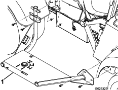
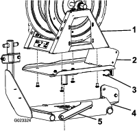
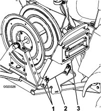
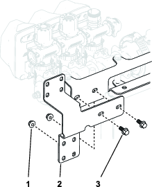
Mount the hose-reel frame to the side of the machine using 4 bolts (5/16 inch) and 4 flange nuts (5/16 inch) as shown in Figure 8.
-
Attach the swivel plate to the bottom of the hose reel using 4 carriage bolts and 4 flange nuts (3/8 inch) (Figure 9).
-
Drop the swivel plate into the hole on the hose-reel frame (Figure 9).
Note: Move the swivel lock to the left for ease of installation.
-
On the underside of the hose reel frame, attach the thrust washer and snap ring to the post on the swivel plate (Figure 10).
-
Loosely mount the handle to the swivel plate with 4 bolts (5/16 inch) (Figure 11).
-
Attach the mud shield and handle to the swivel plate using the bolts installed in step 5 and 4 flange nuts (5/16 inch) (Figure 11).
-
Secure the top of the mud shield to the handle using 2 self-tapping screws (Figure 12).
-
Attach the spray gun holder to the mud shield as shown in Figure 12.
-
Connect the wire harness to the hose reel.
Removing the Actuator and Valve Cluster
Note: Retain all removed parts for later installation unless otherwise noted.
-
Remove the retainer that secures the actuator to the manifold valve for the section valve or agitation valve (Figure 13).
Note: Squeeze the 2 legs of the retainer together while pushing it down.
Note: Retain the actuator and retainer.
-
Remove the actuator from the manifold valve.
-
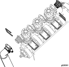
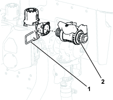
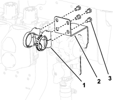
Remove the retainers holding the boom bypass valve cluster assembly, end cap, and the fitting and hose assembly as shown in Figure 14.
Important: If your machine has GeoLink installed, do this for the valve clusters on both sides.
Note: You will not use the male cap, but keep the O-ring that is on the cap.
-
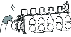
Note and record the current left and right knob settings.
Important: If your machine has GeoLink installed, record all of the knob settings.
-
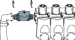
Rotate the boom bypass valve cluster 180° as shown in Figure 15.
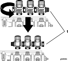
-
Adjust the left and right knobs to the previous settings.
Important: If your machine has GeoLink installed, adjust all of the knobs to their previous settings.
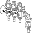
-
Install the boom valve cluster using the retainers previously removed as shown in Figure 16.
Installing the Control Valve
Parts needed for this procedure:
| Flanged control valve | 1 |
| Wing handle | 2 |
| Handle screw (6-32 x 5/8 inch) | 2 |
| Valve mount | 2 |
| 90° elbow | 1 |
| Flange clamp | 1 |
| Gasket | 1 |
| Fitting cap (1/2 inch) | 2 |
| Straight fitting | 1 |
| Retainer | 3 |
| Straight control valve | 2 |
| Control-valve bracket (serial number 415399999 and before) | 1 |
| Flange-head bolt (1/4 x 5/8 inch) | 2 |
| Locknut (1/4 inch) | |
| Control-valve bracket (serial number 415400000 and after) | 1 |
| Control-valve bracket (serial number 415400000 and after with GeoLink) | 1 |
| T-manifold | 1 |
| Carriage bolt (1/4 x 5/8 inch) | 2 |
| Bolt (M6 x 12 mm) | 8 |
| Hose-reel supply hose | 1 |
| Hose clamp | 1 |
Installing the Control Valve to the Machine
Note: Retain all removed parts for later installation unless otherwise noted.
-
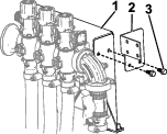
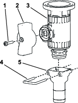
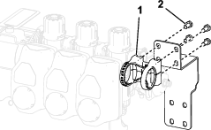
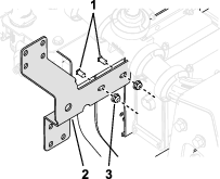
Install the control-valve bracket onto the valve-mount frame using 2 flange-head bolts (1/4 x 5/8 inch) as shown in Figure 17.
-
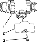
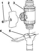
Assemble the red wing handle to the control valve as shown in Figure 18.
-
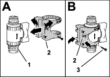
Assemble the valve mount onto the control valve as shown in A of Figure 19.
-
Secure the valve mount to the control valve with the flange-head screw (#6), and tighten the screw by hand (B of Figure 19).
-
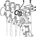
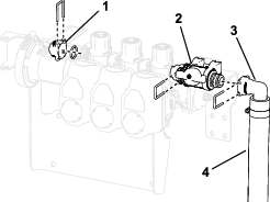
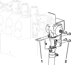
Install the control valve assembly onto the control-valve bracket using 4 bolts (M6) as shown in Figure 20.
-
Secure the control valve assembly to the boom valve with the previously removed O-ring and retainer (Figure 21).
-
Install the cap (1/2 inch), O-rings, fitting, and hose assembly onto the control valve using the retainers previously removed as shown in Figure 21.
-
Install the actuators removed in Figure 13 to the manifold valve using the previously-removed retainers.
-
Remove the pressure-sense hose from the coupler.
-
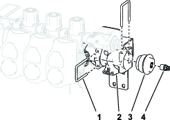
Assemble the green wing handle and straight fitting to the flanged control valve using the retainer as shown in Figure 22.
-
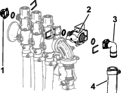
Disconnect the cap and coupler from the pressure-gauge port (Figure 23).
-
Install the control valve assembly vertically as shown in Figure 23.
-
Install the coupler into the open port on the 90° fitting (Figure 23).
Note: The cap can be discarded.
-
Connect the pressure-sense hose to the coupler.
-
Connect the tank-supply hose to the horizontal control valve using a hose clamp.
-
Secure the open end of the hose-reel supply hose to the straight fitting with a hose clamp.
-
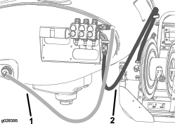
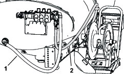
Route the hose-reel supply hose as shown in Figure 24 and attach it to the hose reel with a hose clamp.
Note: If the Tank Cleanse Rinse Kit is installed, route the hose behind the rinse pump.
Installing the Control Valve to the Machine
-
Install the actuators removed in Figure 13 to the manifold valve using the previously-removed retainers.
-
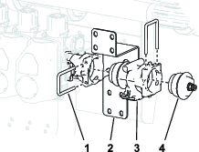
Install the control valve bracket onto the valve-mount frame using 2 flange-head bolts (1/4 x 5/8 inch) and locknuts (1/4 inch) as shown in Figure 25.
-
Assemble the red wing handle to a straight control valve.
-
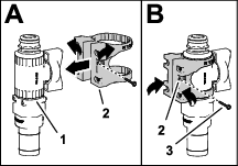
Assemble the valve mount onto a straight control valve as shown in A of Figure 27.
-
Secure the valve mount to the control valve with the flange-head screw (#6), and tighten the screw by hand (B of Figure 27).
-
Install the control valve assembly onto the top of the control valve bracket using 4 screws (M6) as shown in Figure 28.
-
Secure the control valve assembly to the boom valve with the previously removed O-ring and retainer as shown in Figure 29.
-
Install the cap (1/2 inch), O-rings, fitting, and hose assembly onto the control valve using the retainers previously removed as shown in Figure 29.
-
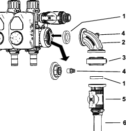
Remove the retainer that secures the fitting cap and coupler from the end of the valve section (Figure 30).
-
Install the included T-manifold to the end of the valve section using the retainer used in step 9.
-
Install the fitting cap to the side of the T-manifold installed in step 9.
-
Assemble the straight fitting to the other straight control valve using the retainer as shown in Figure 31.
-
Connect the hose–reel supply hose to the bottom of the straight fitting.
-
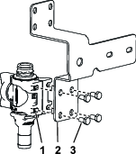
Connect the control valve assembly with the straight fitting to the bottom of the T-manifold using the included retainer (Figure 32).
-
Install the control valve assembly onto the bottom of the control valve bracket using 4 bolts (M6) as shown in Figure 32.
-
Connect the tank-supply hose to the horizontal control valve using a hose clamp.
-
Secure the open end of the hose-reel supply hose to the straight fitting with a hose clamp.
-
Route the hose-reel supply hose as shown in Figure 33 and attach it to the hose reel with a hose clamp.
Note: If the Tank Cleanse Rinse Kit is installed, route the hose behind the rinse pump.
Installing the Control Valve to the Machine
-
Install the actuators removed in Figure 13 to the manifold valve using the previously-removed retainers.
-
Install the control valve bracket onto the valve-mount frame using 2 carriage bolts (1/4-20 x 5/8 inch) and 2 locknuts (1/4-20 inch) as shown in
-
Remove the retainer that secures the fitting cap and coupler from the end of the valve section (Figure 35).
-
Install the kit T-manifold to the end of the valve section using the retainer removed in step 3.
-
Assemble the green wing handle to a straight control valve Figure 36.
-
Assemble the valve mount onto a straight control valve as shown in A of Figure 37.
-
Secure the valve mount to the control valve with the flange-head screw (#6), and tighten the screw by hand (B of Figure 37).
-
Secure the hose-reel supply hose to the straight fitting with a hose clamp.
-
Secure the control-valve assembly to the T-fitting with a retainer as shown in Figure 38.
-
Assemble the valve mount to the control-valve bracket with the 4 flange-head bolts (M6 x 12 mm); torque the bolts to 10 to 12 N∙m (86 to 106 in-lb).
-
Assemble the valve mount onto the control valve as shown in A.
-
Secure the valve mount to the control valve with the flange-head screw (#6), and tighten the screw by hand as shown in B.
-
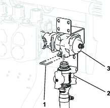
Install the control-valve assembly to the valve cluster as shown in Figure 41.
-
Install the control-valve assembly onto the top of the control valve bracket using 4 screws (M6) as shown in Figure 42.
-
Install the caps (1/2 inch), O-rings, fittings, and hose assemblies onto the control valves using the retainers previously removed.
-
Remove the retainer securing the hose to the end of the manifold.
-
Install the shutoff valve on the hose and machine. Secure them with the retainers.
-
Connect the tank-supply hoses to the horizontal control valve using a hose clamp.
-
Route the hose-reel supply hose as shown in and attach it to the hose reel with a hose clamp.
Note: If the Tank Cleanse Rinse Kit is installed, route the hose behind the rinse pump.
Connecting the Hoses
Parts needed for this procedure:
| Long hose with fitting | 1 |
| Spray gun | 1 |
| Plastic hose clamp | 1 |
-
Cable tie the wire harness to the supply hose using 2 cable ties.
-
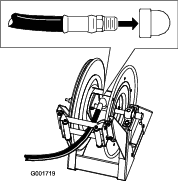
Wrap Teflon® tape around the threads of the hose fitting on the long hose, and install the fitting into the connecting tube on the reel (Figure 46).
-
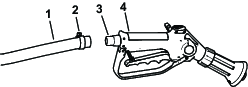
Connect the free end of the long hose to the fitting on the spray gun (Figure 47).
-
Secure the end of the hose with a plastic hose clamp.
-
Connect the positive battery wire to the battery.
-
Connect the negative battery wire to the battery.
-
Press the hose wind button, and carefully guide the hose onto the reel moving the hose from side to side to evenly distribute the hose.
Caution
Hands, loose clothing, long hair, and jewelry could get caught in the hose and reel while rewinding and cause injury.
-
Keep your hands clear of the reel and hose while it is rewinding.
-
Do not wear loose clothing or jewelry and tie up long hair.
-
Operation
Warning
Fluid under pressure can penetrate skin and cause injury.
-
Keep your body and hands away from nozzles that eject high-pressure fluid.
-
Do not aim the sprayer at any person or animal.
-
Make sure that all fluid hoses and lines are in good condition and that all connections and fittings are tight before applying pressure to the system.
-
Use cardboard or paper to find leaks.
-
Safely relieve all pressure in the system before performing any work on it.
-
Get immediate medical help if fluid is injected into skin.
-
Hot liquids and chemicals can cause burns or other harm.
Important: You must always empty and clean the sprayer immediately after each use. Failure to do so may cause the chemicals to dry or thicken in the lines, clogging the pump and other components.
Clean the spray system after each spraying session. To properly clean the spray system:
-
Use 3 separate rinses.
-
Use a minimum of 50 gallons for each rinse.
-
Use the cleaners and neutralizers as recommended by the chemical manufacturers.
-
Use pure clean water (no cleaners or neutralizers) for the last rinse.
Switching from Boom Spray Mode to Hand Spray Mode
-
Stop the machine, turn the booms off, and set the parking brake.
Warning
Driving while using the hand sprayer can cause loss of control, resulting in injury or death. Do not operate the hand sprayer while driving.
-
At the back of the machine, ensure that the trigger lock on the spray gun is locked.
-
Rotate the green handle on the control vale 90°.
-
At the operating position, turn the pump on.
-
Switch the master boom to the ON position.
-
Set the engine to the desired speed, then engage the neutral engine speed lock.
Important: Do not use a pressure setting higher than 1034 kPa (150 psi) with the hand sprayer.
Spraying with the Hand Sprayer
-
Pull out the desired amount of hose from the reel.
Important: Do not pull the hose with the spray gun. Always hold the hose and pull on it directly. Pulling on the hose with the gun may break the fitting on the gun or damage the hose.
-
Release the trigger lock.
-
Direct the spray gun nozzle at the area to be sprayed and pull the trigger.
-
Release the trigger and set the trigger lock when you are finished.
Switching from Hand Spray Mode to Boom Spray Mode
-
Press the rewind button on the hose reel until only a few feet of hose is out of the reel.
Note: The hose-reel rewind button can only be used when the supervisor key on the sprayer console is in the unlocked position.
Caution
Hands, loose clothing, long hair, and jewelry could get caught in the hose and reel while rewinding and cause injury.
-
Keep your hands clear of the reel and hose while it is rewinding.
-
Do not wear loose clothing or jewelry and tie up long hair.
-
-
Rotate the green handle on the control vale 90°.
-
Direct the spray gun nozzle at an area where it is safe to spray, release the trigger lock, and pull the trigger until all remaining fluid is out of the hose, then set the trigger lock.
-
Return the spray gun to the holder on the back of the reel.
-
Return the engine to idle speed.
-
Stop the pump.
Important: Ensure that you flush the spray gun with fresh clean water during your daily cleaning routine (refer to your sprayer Operator's Manual). Failure to properly clean the spray gun may degrade the performance and reliability of the hose reel kit and spray gun.
-
Use the rate switch to set the desired kPa (psi).