
 , which means
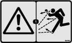
Caution, Warning, or Danger—personal safety instruction. Failure
to comply with these instructions may result in personal injury or
death.
, which means
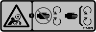
Caution, Warning, or Danger—personal safety instruction. Failure
to comply with these instructions may result in personal injury or
death.


Maintenance
Note: Determine the left and right sides of the machine from the normal operating position.
Note: Download a free copy of the electrical or hydraulic schematic by visiting www.Toro.com and searching for your machine from the Manuals link on the home page.
Maintenance Safety
-
Before you leave the operator’s position, do the following:
-
Park the machine on a level surface.
-
Shut off hydraulic control to the machine.
-
Engage the parking brake.
-
Shut off the engine and remove the key (if equipped).
-
Wait for all movement to stop.
-
-
Allow machine components to cool before performing maintenance.
-
Perform only those maintenance instructions described in this manual. If major repairs are ever needed or assistance is desired, contact an authorized Toro distributor.
-
Ensure that the machine is in safe operating condition by keeping nuts, bolts, and screws tight.
-
If possible, do not perform maintenance while the engine is running. Keep away from moving parts.
-
Do not check or adjust the chain tension when the vehicle engine is running.
-
Carefully release pressure from components with stored energy.
-
Support the machine with jack stands whenever you work under the machine.
-
After maintaining or adjusting the machine, ensure that all guards are installed.
-
Keep all parts of the machine in good working condition and all hardware tightened.
-
Replace all worn or damaged decals.
-
To ensure safe, optimal performance of the machine, use only genuine Toro replacement parts. Replacement parts made by other manufacturers could be dangerous, and such use could void the product warranty.
Recommended Maintenance Schedule(s)
| Maintenance Service Interval | Maintenance Procedure |
|---|---|
| Before each use or daily |
|
| Every 40 hours |
|
| Every 200 hours |
|
Pre-Maintenance Procedures
Preparing for Maintenance
-
Shut off the machine by doing the following:
-
239999999 and before, move the remote hydraulic valve handle to the OFF position.
-
240000001 and up, move the hydraulic lift lever to the OFF position.
-
-
Move the machine to a level surface.
-
Set the parking brake of the Workman vehicle, shut off the engine, remove the key, and wait for all moving parts to stop before leaving the operator’s seat.
Lubrication
Grease Specification
No. 2 Lithium based grease
Greasing the Bearings and Bushings
| Maintenance Service Interval | Maintenance Procedure |
|---|---|
| Every 200 hours |
|
-
Perform the steps in Preparing for Maintenance.
-
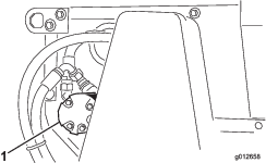
Lubricant each of the grease fitting described in the grease-fitting table with the specified grease.
| Location | Quantity |
|---|---|
| Roller shaft bearing (Figure 22) | 4 |
| Brush shaft bearing (Figure 22) | 1 |
Important: Lubricate the bearings to maintain a slight leakage between bearings and housings. Too much grease can cause overheating or damage to seals.
Note: Do not lubricate the drive chains unless they become stiff from rust. If the chain rusts, lightly lubricate it with a dry-type lubricant. This reduces the likelihood of sand build-up or other top-dressing material adhering to the chain.
Belt Maintenance
Tensioning the Conveyor-Belt Chain
-
Perform the steps in Preparing for Maintenance.
-
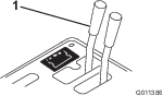
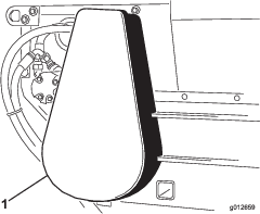
Remove the chain cover (Figure 23).
-
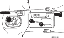
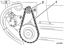
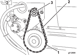
Loosen bolts and nuts that secure the motor and sprocket assembly to the main frame (Figure 24).
-
Rotate motor and sprocket assembly (Figure 24) in mounting slots until the conveyer-belt chain deflects 3.2 mm (1/8 inch).
Important: Do not over tension the chain or it will wear prematurely. Do not under-tension the chain or it will cause sprocket wear.
-
Tighten mounting bolts (Figure 24).
-
Install chain cover (Figure 23).
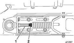
Tensioning the Conveyor Belt
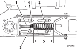
When conveyor belt is adjusted properly, the compressed length of each compression spring should be 112 mm (4-7/16 inches). Adjust conveyor belt as follows:
-
Empty the hopper.
-
Perform the steps in Preparing for Maintenance.
-
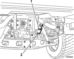
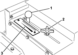
Loosen rear jam nut (Figure 25).
-
Adjust forward jam nut to compression spring to 112 mm (4-7/16 inches).
-
Tighten jam rear nut.
-
Repeat steps 3 through 5 at the other side of the machine.
-
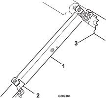
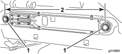
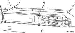
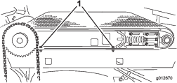
Measure the distance between center points of the belt-roller shafts at each side of machine to ensure that the measurements are equal (Figure 26).
Equal distance measures approximately 895 mm (35-1/4 inches).
Replacing the Conveyor Belt
Preparing to Machine
-
Empty the hopper.
-
Perform the steps in Preparing for Maintenance.
-
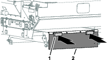
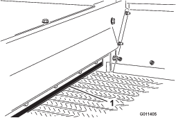
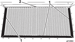
Inspect hopper seals and gate edge for wear or torn edges (Figure 27).
Replace worn or damaged components to ensure proper operation of new conveyor belt.
Removing the Conveyer Chain
Disassembling the Slider Bed
-
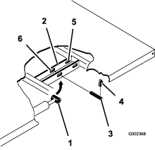
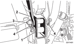
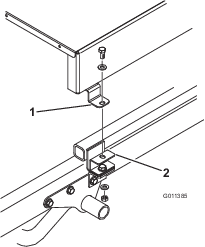
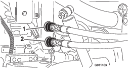
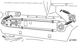
Loosen forward and rear jam nuts on tension rod to release spring tension (Figure 30).
-
At each side of machine, remove 2 capscrews, 2 washers, and 2 locknuts that secure the hopper to slider-frame rails (Figure 31).
-
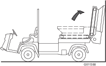
Pivot hopper rearward and lean it against wall, post, ladder, etc. (Figure 32).
Important: Do not allow hopper to rest against the rear of machine to avoid damaging the brush or the hydraulic couplers.Make sure that the hopper is pivoted beyond center and/or secured to wall or post to prevent it from accidentally falling on work area (Figure 32).
-
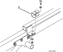
At the right side of machine, loosen 2 capscrews that secure slider-frame rail to the right fender (Figure 33). Ensure that the capscrews are loose enough to allow slider bed tip.
-
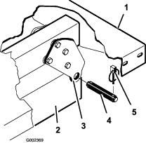
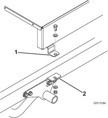
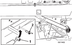
At the left side of machine, remove 2 capscrews and 2 washers that secure slider-frame rail to the left fender (Figure 34).
Removing the Belt
Cut belt and remove it from rollers.
Installing the Belt
-
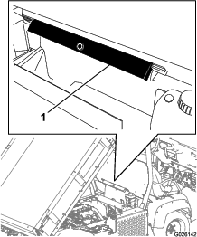
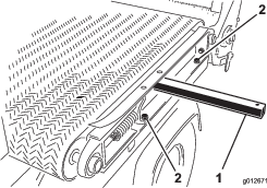
Insert a lift bar though the hole at the left slider-frame rail, and raise the lift bar to tip frame rail slightly; refer to Figure 34 in Disassembling the Slider Bed.
-
Assemble the belt over the lift bar and rollers as far as possible.
-
Insert a plastic belt tool between each roller and the belt.
Rotate rollers until each tool is positioned to the outside of each roller. Insert the tool past rib in the center of belt.
-
Slide belt and belt tools further onto rollers until belt is centered on rollers.
-
Remove belt tools.
-
Align belt so that the belt rib fits into alignment grooves in each roller.
Assembling the Slider Bed
-
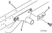
At the left side of machine, assemble the slider-frame rail to the left fender (Figure 35) with the 2 capscrews and 2 washers that you removed in Disassembling the Slider Bed, and tighten the capscrews.
-
At the right side of machine, tighten 2 capscrews that secure slider-frame rail to the right fender (Figure 36).
-
Carefully rotate the hopper down onto the slider-frame rails; refer to Figure 32 of Disassembling the Slider Bed.
-
At each side of machine, secure the hopper to slider-frame rails (Figure 37) with the 2 capscrews, 2 washers, and 2 locknuts that you removed in Disassembling the Slider Bed.
-
Tension the conveyer belt; refer to Tensioning the Conveyor Belt.
Installing the Conveyer Chain
-
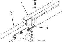
Assemble the chain onto the small sprocket and secure the chain with the master link (Figure 38).
-
If you loosen the motor-mount bolts, tension the conveyer-belt chain, refer to Tensioning the Conveyor-Belt Chain.
-
Install the chain cover (Figure 39).
Hydraulic System Maintenance
Hydraulic System Safety
-
Seek immediate medical attention if fluid is injected into skin. Injected fluid must be surgically removed within a few hours by a doctor.
-
Ensure that all hydraulic-fluid hoses and lines are in good condition and all hydraulic connections and fittings are tight before applying pressure to the hydraulic system.
-
Keep your body and hands away from pinhole leaks or nozzles that eject high-pressure hydraulic fluid.
-
Use cardboard or paper to find hydraulic leaks.
-
Safely relieve all pressure in the hydraulic system before performing any work on the hydraulic system.
Checking the Hydraulic Lines and Hoses
| Maintenance Service Interval | Maintenance Procedure |
|---|---|
| Before each use or daily |
|
Check the hydraulic lines and hoses for leaks, kinked lines, loose mounting supports, wear, loose fittings, weather deterioration, and chemical deterioration. Make all necessary repairs before operating.
Brush Maintenance
Checking the Brush for Position and Wear
| Maintenance Service Interval | Maintenance Procedure |
|---|---|
| Every 40 hours |
|
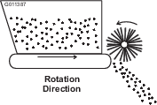
Brush must make enough contact with conveyor belt to disperse top-dressing material but not restrict the rotation of the brush. A piece of stiff paper can be inserted between the conveyor belt and the brush to check the adjustment.
-
Insert a piece of stiff between the conveyor belt and the brush to check the adjustment.
-
Check that the brush is same height from side to side.
-
Check the condition of the brush bristles.
If the bristles are excessively worn replace the brush. If the bristles are worn uneven either replace the brush or adjust the brush position; refer to Adjusting the Brush Position.
Adjusting the Brush Position
Note: If you are using moist top-dressing material, you may need to adjust the brush position so that the bristles will whisk material from between conveyor belt lugs without excessively contacting smooth portion of belt.
-
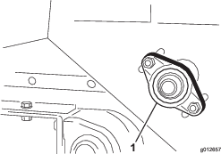
Loosen nuts that secure the bearing housing (Figure 40) to right side of machine.
-
Loosen nuts that secure the brush motor (Figure 41) to left side of machine.
-
Slide brush into position at right side, and snug the nuts.
-
Slide brush into position at left side, and snug the nuts.
-
Insert a piece of stiff paper between the brush and the conveyor belt.
The brush must be the same height from side to side.
-
If the brush position is correct, tighten nuts.
If the brush position is not correct, repeat steps 1 through 6.
Cleaning
Washing the Machine
Wash the machine as needed using water alone or with a mild detergent. You may use a rag when washing the machine.
Important: Do not use brackish or reclaimed water to clean the machine.
Important: Do not use power-washing equipment to wash the machine. Power-washing equipment may damage the electrical system, loosen important decals, or wash away necessary grease at friction points. Avoid excessive use of water near the control panel.