Before Operation
Performing Daily Maintenance
Before starting the machine each day, perform the Each Use/Daily procedures listed in the Maintenance Schedule.
Fuel
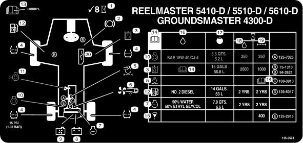
Fuel Specifications
Use only ultra-low sulphur diesel fuel. Fuel with higher rates of sulfur degrades the diesel oxidation catalyst (DOC), which
causes operational problems and shortens the service life of engine components.
Failure to observe the following cautions may damage the engine.
- Never use kerosene or gasoline instead of diesel fuel.
- Never mix kerosene or used engine oil with the diesel fuel.
- Never keep fuel in containers with zinc plating on the inside.
- Do not use fuel additives.
Petroleum Diesel
|
Type
|
Use summer grade diesel fuel (No. 2-D) at temperatures above -7°C (20°F) and winter grade (No. 1-D or No. 1-D/2-D blend) below
that temperature. Use of winter grade fuel at lower temperatures provides lower flash point and cold flow characteristics
which eases starting and reduces fuel filter plugging.
Use of summer grade fuel above -7°C (20°F) contributes toward longer fuel pump life and increased power compared to winter
grade fuel.
|
|
Sulfur content
|
Ultra low (<15 ppm)
|
|
Minimum Cetane Rating
|
45
|
|
Storage
|
Acquire only enough clean, fresh diesel fuel or biodiesel fuel that you will consume within 180 days. Do not use fuel that
has been stored for more than 180 days.
|
|
Oil and additives
|
Do not add to the fuel
|
| |
|
Diesel fuel must meet:
|
Standard
|
Location
|
|
ASTM D975
|
USA
|
|
No. 1-D S15
|
|
No. 2-D S15
|
|
EN 590
|
European Union
|
|
ISO 8217 DMX
|
International
|
|
JIS K2204 Grade No. 2
|
Japan
|
|
KSM-2610
|
Korea
|
Biodiesel
|
Type
|
This machine can also use a biodiesel-blended fuel of up to B20 (20% biodiesel, 80% petroleum diesel).
The petroleum diesel portion must be ultra low sulfur (<15 ppm).
Use B5 (biodisel content of 5%) or lesser blends in cold weather
|
|
Minimum Cetane Rating
|
40
|
|
Biodiesel Precautions
|
Painted surfaces may be damaged by biodiesel blends.
Monitor seals, hoses, gaskets in contact with fuel as they may degrade over time.
Fuel filter plugging may be expected for a time after converting to biodiesel blended.
For more information on biodiesel, contact your authorized Toro distributor.
|
|
Storage
|
Acquire only enough clean, fresh diesel fuel or biodiesel fuel that you will consume within 180 days. Do not use fuel that
has been stored for more than 180 days.
|
|
Oil and additives
|
Do not add to the fuel
|
| |
|
|
|
Biodiesel fuel must meet:
|
Standard
|
Location
|
|
ASTM D6751
|
USA
|
|
EN 14214
|
European Union
|
|
Blended fuel must meet:
|
ASTM D975
|
USA
|
|
EN 590
|
European Union
|
|
JIS K2204
|
Japan
|
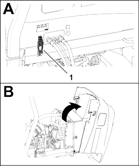
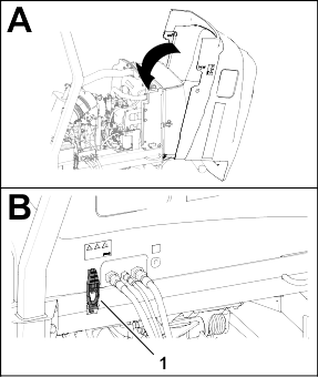
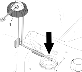
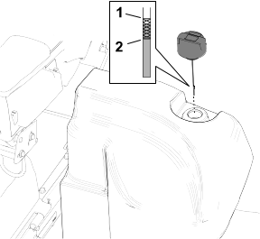
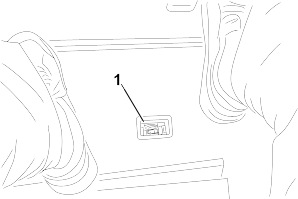
Adding Fuel
-
Park the machine on a level surface, lower the cutting units, shut off the engine, engage the parking brake, and remove the
key.
-
Using a clean rag, clean area around fuel-tank cap.
-
Remove the cap  from the fuel tank.
-
Fill the tank until the level is 6 to 13 mm (1/4 to 1/2 inch) below the bottom of the filler neck.
-
Install the fuel-tank cap tightly after filling the tank.
Note: If possible, fill the fuel tank after each use. This minimizes possible buildup of condensation inside the fuel tank.
Checking the Interlock Switches
 |
Caution |
|
If safety interlock switches are disconnected or damaged, the machine could operate unexpectedly, resulting in minor or moderate
injury.
- Do not tamper with the interlock switches.
- Check the operation of the interlock switches daily and replace any damaged switches before operating the machine.
If your machine fails any of the interlock switch checks, contact your authorized Toro distributor.
Preparing the Machine
-
Drive the machine slowly to an open area.
-
Lower the cutting units, shut off the engine, and engage the parking brake.
Checking the Traction Pedal Start-Interlock
-
Sit in the operator’s seat and engage the parking brake.
-
Press the PTO switch to the Disengage position.
-
Press the traction pedal and rotate the key to the Start position.
Note: The engine should not start with the traction pedal pressed.
Checking the PTO-Start Interlock
-
Sit in the operator’s seat.
-
Press the PTO switch to the Engage position.
-
Rotate the key to the Start position.
Note: The engine should not start with the PTO switch in the Engage position.
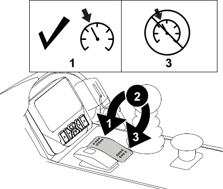
Checking the PTO-Run Interlock
Note: Do not allow the cutting units to spin for more than a couple seconds during this test to prevent unnecessary wear.
-
Sit in the operator’s seat.
-
Press the PTO switch to the Disengage position.
-
Start the engine.
-
Pull up the PTO switch to the Engage position.
-
Lower the cutting units to engage the PTO.
-
Rise from the seat.
Note: The PTO should not run when you are out of the operator’s seat.
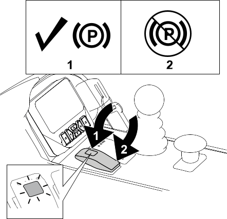
Checking the Parking Brake and Traction Pedal Run-Interlock
-
Sit in the operator’s seat.
-
Engage the parking brake.
-
Press the PTO switch to the Disengage position.
-
Start the engine.
-
Press the traction pedal.
Note: There should be no machine response when you press the traction pedal while the parking brake is engaged. An advisory message
should appear on the InfoCenter display.
Checking the Automatic Parking Brake Engage
-
Sit in the operator’s seat and start the engine.
-
Disengage the parking brake and rise from the seat.
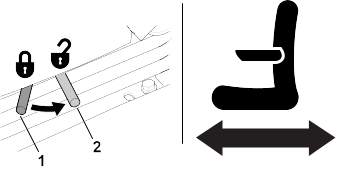
Note: The red light on the parking-brake switch should illuminate when you are out of the operator’s seat, indicating that the parking brake is on.
Checking the Cutting Unit Lower Disable Interlock
-
Sit in the operator’s seat and start the engine.
-
Ensure that the cutting units are lifted to the transport position.
-
Rise from the seat and lower the cutting units.
Note: The cutting units should not lower when you are out of the operator’s seat.
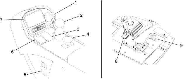
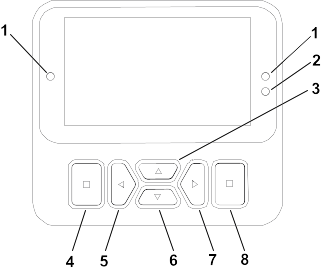
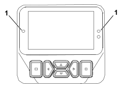
Overview of the InfoCenter Display
The InfoCenter display shows information about your machine such as the operating status, various diagnostics and other information
about the machine. There are multiple screens on the display. You can switch between the screens, at any time, by pressing
the back button and then using the up and down directional buttons.
G471371s
-
Indicator light
-
Display brightness sensor
-
Navigation button—up
-
Back button
-
Navigation button—decrease/left
-
Navigation button—down
-
Navigation button—increase/right
-
Enter button
Note: The purpose of each button may change depending on what is required at the time. Each button is labeled with an icon displaying
its current function.
InfoCenter Display Icons
|
|
Service is due.
|
|
|
Engine-coolant temperature (°C or °F)
|
|
|
Engine rpm/status—indicates the engine speed (rpm)
|
|
|
The PTO is engaged.
|
|
|
Hour meter
|
|
|
Start the engine.
|
|
|
Fuel level
|
|
|
Engine
|
|
|
Fuel is low.
|
|
|
PIN passcode
|
|
|
The glow plugs are active.
|
|
|
A parked or recovery regeneration is requested.
Perform the regeneration immediately.
|
|
|
The cutting units are up or raising.
|
|
|
A regeneration is acknowledged and the request is processing.
|
|
|
The cutting units are down or lowering.
|
|
|
A regeneration is in progress and the exhaust temperature is elevated.
|
|
|
Sit in the seat.
|
|
|
NOx control system malfunction; the machine requires service.
|
|
|
The parking brake is on.
|
|
|
Battery voltage
|
|
|
Warm-up mode
|
|
|
Traction or Traction pedal
|
|
|
Fault/warning
|
|
|
Increase value
|
|
|
Locked
|
|
|
Decrease value
|
|
|
The cruise control is engaged.
|
|
|
Scroll up/down
|
|
|
Active
|
|
|
Scroll left/right
|
|
|
Inactive
|
|
|
Menu
|
|
|
Next screen
|
|
|
Previous screen
|
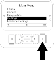
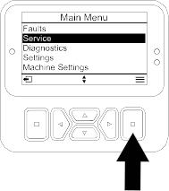
Overview of the Menus
To access the InfoCenter display menu system, press the back button while at the main screen. This brings you to the main
menu. Refer to the following tables for a synopsis of the options available from the menus.
 Protected under Protected Menus—accessible only by entering PIN
Main Menu
|
Faults
|
The Faults menu contains a list of the recent machine faults. Refer to the Service Manual or contact your authorized Toro distributor for more information on the Faults menu and the information contained there.
|
|
Service
|
The Service menu contains information on the machine such as hours of use, counters, and other similar numbers.
|
|
Diagnostics
|
The Diagnostics menu displays the state of each machine switch, sensor, and control output. You can use this to troubleshoot
certain issues as it quickly tells you which machine controls are on and which are off.
|
|
Settings
|
The Settings menu allows you to customize and modify configuration variables on the display.
|
|
Machine Settings
|
The Machine Settings menu allows you to adjust the acceleration, speed, and counterbalance thresholds.
|
|
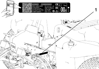
About
|
The About menu lists the model number, serial number, and software version of your machine.
|
Service
|
Hours
|
Lists the total number of hours that the machine, engine and PTO have been on, as well as the number of hours the machine
has been transported and service due.
|
|
Counts
|
Lists numerous counts the machine has experienced.
|
|
DPF Regeneration
|
The diesel particulate filter regeneration option and DPF submenus
|
Traction Pedal
|
Calibrates the traction pedal.
|
Traction Pump
|
Calibrates the traction pump.
|
Virtual Speed Sensor
|
Calibrates the virtual speed sensor.
|
Diagnostics
|
Traction
|
Indicates the inputs and outputs for the traction pedal.
|
|
Cutting Units
|
Indicates the inputs, qualifiers and outputs for raising and lowering the cutting units.
|
|
PTO
|
Indicates the inputs, qualifiers and outputs for enabling the PTO circuit.
|
|
Engine
|
Indicates the inputs, qualifiers and outputs for starting the engine.
|
|
CAN Statistics
|
Indicates the inputs and outputs for the CAN.
|
Settings
|
Enter PIN
|
Allows a person (superintendent/mechanic) authorized by your company with the PIN code to access protected menus.
|
|
Backlight
|
Controls the brightness of the LCD display.
|
|
Language
|
Controls the language used on the display*.
|
|
Font Size
|
Controls the size of the font on the display.
|
|
Units
|
Controls the units used on the display (Imperial or Metric).
|
Protect Settings
|
Allows the ability to change the settings in the protected settings.
|
Machine Settings
|
Front Backlap
|
Controls the speed of the front reels in backlap mode.
|
|
Rear Backlap
|
Controls the speed of the rear reels in backlap mode.
|
Mow Speed
|
Controls the maximum speed while in mow (low range). This is used for determining the reel speed.
|
Transport Speed
|
Controls the maximum speed while in transport (high range).
|
Blade Count
|
Controls the number of blades on the reel for reel speed.
|
Height of cut (HOC)
|
Controls the height of cut (HOC) for determining the reel speed.
|
Front Reel Speed
|
Displays the calculated reel speed position for the front reels. The reels can also be manually adjusted.
|
Rear Reel Speed
|
Displays the calculated reel speed position for the rear reels. The reels can also be manually adjusted.
|
Eco Mode
|
When activated, the Economy Mode lowers the engine speed while mowing to reduce noise and fuel consumption. The reel speed
does not change, but the mow speed is decreased if the mow stop is not adjusted accordingly.
|
Smart Power
|
Turns Smart Power on and off.
|
Acceleration
|
Low, Medium, and High settings control how quickly the traction speed reacts when you move the traction pedal.
|
About
|
Model
|
Lists the model number of the machine.
|
|
SN
|
Lists the serial number of the machine.
|
|
S/W Revision
|
Lists the software revision of the primary controller.
|
InfoCenter S/W Revision
|
Lists the software revision of the InfoCenter.
|
Accessing Run Screens
-
From the Main Menu, press the right navigation button to access the Main Run Screen displaying the fuel level and coolant temperature.
-
Press the right navigation button to scroll to the Secondary Run Screen displaying the fuel level, coolant temperature, hours, battery voltage, and RPMs.
Protected Menus
There are operating configuration settings that are adjustable within Settings of the display. To lock these settings, use the Protected Menu.
Note: At the time of delivery, the initial password code is programmed by your distributor.
Accessing Protected Menus
Note: The factory default PIN code for you machine is either 0000 or 1234.
If you changed the PIN code and forgot the code, contact your authorized Toro distributor for assistance.
-
From the Main Menu, scroll down to Settings and press the select button.
-
In Settings, scroll to Enter PIN and press the select button  .
.
-
To enter the PIN code, press the up/down navigation buttons  until the correct first digit appears, then press the right navigation button
 to move on to the next digit. Repeat this step until the last digit is entered.
-
Press the select button  .
.
Note: If the display accepts the PIN code and the protected menu is unlocked, the word “PIN” displays in the upper right corner of the screen.
-
To lock the protected menu, rotate the key switch to the Off position and then to the On position.
Viewing and Changing the Protected Menu Settings
-
In Settings, scroll down to Protect Settings.
-
To view and change the settings without entering a PIN code, use the select button to change the Protect Settings to  (Off).
-
To view and change the settings with a PIN code, use the select button to change the Protect Settings to  (On), set the PIN code, and turn the key in the ignition switch to the Off position and then to the On position.
Setting the Service Due Timer
The service due timer resets the service due hours after a scheduled maintenance procedure is performed.
-
In Settings, scroll to Enter PIN and press the select button.
-
Enter PIN; refer to Accessing Protected Menus.
-
In Service, navigate to Hours and press the select button.
-
Scroll down to Service Due.
Note: If service is currently due, Now appears next to Service Due.
-
Highlight the service interval and press the select button.
Note: The service interval (250 Hrs, 500 Hrs, etc) is located next to Service Due.
Service interval is a protected menu item.
-
When the Reset Service Timer? screen appears, press the select button for Yes or the back button for No.
-
After you select Yes, the interval screen clears and reverts back to the service hours selections.
Setting the Blade Count
-
In Machine Settings, scroll down to Blade Count.
-
Press the right navigation button to change the blade count between 8 or 11 blade reels.
Setting the Height of Cut (HOC)
-
In Machine Settings, scroll down to Height of Cut.
-
Use the left and right navigation buttons to select the HOC setting that matches the bench setting of the cutting units. If
the exact setting is not displayed, select the nearest HOC setting from the list displayed.
Setting the Front and Rear Reel Speeds
Although the front and rear reel speeds are calculated by inputting the number of blades, mow speed and HOC into the InfoCenter
display, the setting can be manually changed to accommodate for different mowing conditions.
-
To change the Reel Speed Settings, scroll down to the F Reel RPM, R Reel RPM, or both.
-
Press the right button to change the reel speed value. As you change the speed setting, the display continues to show the
calculated reel speed based on blade count, mow speed and HOC, which was previously entered, but the new value is also displayed.
Setting the Maximum Allowed Mow Speed
The selected setting is displayed as an X on the traction-speed bar graph along with the cruise control and pedal stop settings. An X in a bar denotes that the maximum speed is limited by the supervisor.
Note: This setting is retained in memory and applied to the traction speed until you change it.
-
In Machine Settings, scroll down to Mow Speed.
-
Use the left and right navigation buttons to increase and decrease the maximum mow speed in 0.8 km/h (0.5 mph) increments
between 1.6 and 12.9 km/h (1.0 and 8.0 mph).
Setting the Maximum Allowed Transport Speed
The selected setting is displayed as an X on the traction-speed bar graph along with the cruise control and pedal stop settings. An X in a bar denotes that the maximum speed is limited by the supervisor.
Note: This setting is retained in memory and applied to the traction speed until you change it.
-
In Machine Settings, scroll down to Transport Speed.
-
Use the left and right navigation buttons to increase and decrease the maximum transport speed in 0.8 km/h (0.5 mph) increments
between 8.0 and 16.0 km/h (5.0 and 10.0 mph).
Turning the Smart Power ON/OFF
-
In Settings, scroll down to Smart Power.
-
Press the right navigation button to switch between On and Off.
Setting the Acceleration Mode
-
In Machine Settings, scroll down to Acceleration.
-
Press the right navigation button to switch between Low, Medium, and High.
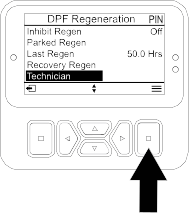
Accessing the Technician Menu
Note: For operating convenience, you may decide to perform a parked regeneration before the soot load reaches 100%, provided the
engine has run more than 50 hours since the last successful reset, parked, or recovery regeneration.
Use the Technician menu to view the current state of engine regeneration control and the current soot level.
-
In Settings, scroll down to DPF Regeneration and press the select button.
-
In DPF Regeneration, scroll down to Technician and press the select button.
Checking the Hydrostatic Braking Distance
Note: This machine will dynamically brake and stop when you return the traction pedal to neutral.
Note: For smooth deceleration, use your foot to slowly control the traction pedal back to neutral. Do not take your foot off the
pedal and allow it to snap back to the neutral position unless you intend to stop quickly.
-
Bring the machine to a complete stop approximately 3.7 m (12 ft) from the maximum transport speed of 10 mph.
-
On flat, dry pavement, mark out the start and end of 3.7 m (12 ft).
-
Drive the machine at the maximum transport speed of 16 km/h (10 mph) and remove your foot at the start of the 3.7 m (12 ft).
-
Check if the machine stops within 0.6 m (2 ft) of the end mark (3.7 m or 12 ft).
-
Contact your Toro distributor if the stopping distance of the machine is not within 0.6 m (2 ft) of this distance.
Overview of Reverse Speeds
Transport Reverse Speed
- If the maximum transport speed set by the supervisor is above 8.0 km/h (5.0 mph), the maximum reverse speed is 8.0 km/h (5.0
mph).
- If the maximum transport speed set by the supervisor is at or below 8.0 km/h (5.0 mph), maximum reverse speed is equal to
the transport speed set by the supervisor.
Mowing Reverse Speed
- If the maximum mow speed set by the supervisor is above 6.4 km/h (4.0 mph), the maximum reverse speed is 6.4 km/h (4.0 mph).
- If the maximum mow speed set by the supervisor is at or below 6.4 km/h (4.0 mph), maximum reverse speed is equal to the transport
speed set by the supervisor.
Overview of Displayed Traction Speeds
This machine displays estimated traction speeds in kilometers per hour (km/h) or miles per hour (mph).
- The instantaneous speed is displayed in the upper left-hand corner of the cruise control and virtual pedal stop screens.
- The traction speeds are estimated, and calibrated to be most accurate at 8.0 km/h (5.0 mph) while mowing. Displayed speeds
are accurate when it is 0.8 km/h (0.5 mph) above or below the display speed while driving on dry, flat pavement.
- Contact your authorized Toro distributor if the machine's observed speeds deviate more than 2.4 km/h (1.5 mph) from the displayed speeds.
During Operation
Overview of the Machine Operating Characteristics
- This machine has an automotive-style throttle that is controlled by the traction pedal.
- This machine does not have a separate throttle switch or throttle lever.
- When you remove your foot from the traction pedal, the machine dynamically brakes to a stop.
- The pedal controls are optimized to provide a reactive yet stable response, allowing you to maintain consistent control over
rough terrain, while still allowing for quick, smooth braking.
- While transporting, the traction pedal will operate similar to a car and change the engine and traction speed dependent on
the traction pedal position.
- When mowing, the engine speed will automatically raise to high idle.
- If the engine is at low idle, performing a function like lifting the cutting units or pressing the traction pedal raises the
engine speed to a minimum working speed, providing enough power to efficiently perform the function.
- The maximum speeds set in the PIN protected menu settings are set by the supervisor to limit the machine’s maximum traction speed.
- The achievable traction pedal use, cruise control, and pedal stop traction speeds are all limited by the maximum speeds set
in the PIN protected menu.
Machine Operation
- If an obstacle is in the way, lift the cutting units or mow around it.
- When transporting the machine between work areas, shut off the PTO, and raise the cutting units to the fully upward position.
This allows the traction pedal to operate like a car.
- Always drive slowly in rough areas.
- Never shut off the machine while driving the machine.
Practice Operating the Machine
To get familiar with the features of the machine, practice operating the machine.
-
Lift the cutting units, disengage the parking brake, press the forward traction pedal, and carefully drive to an open area.
-
Practice driving the machine, because it has a hydrostatic transmission and its features can differ from other turf-maintenance
machines.
-
Practice moving forward and reverse, and starting and stopping the machine. To stop the machine, remove your foot from the
traction pedal and let it return to Neutral.
Note: When going downhill in the machine, you may need to engage the parking-brake switch or use the reverse pedal to stop.
-
Practice driving around obstacles with the cutting units up and down. Be careful when driving between narrow objects so that
you do not damage the machine or cutting units.
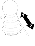
Overview of the Traction Pedal
The traction pedal controls the forward and reverse speed of the machine and the dynamic braking when you return it to neutral.
- This machine has an automotive-style throttle — the engine speed and the machine speed respond to the pedal movement.
- While transporting, the traction pedal will operate similar to a car and change the engine and traction speed dependent on
the traction pedal position.
- While mowing, the engine automatically raises to high idle to optimize mowing performance, and the traction pedal only controls
traction speed.
- The further you push the pedal forward or reverse, the faster the machine moves.
- To control the machine to a smooth stop while transporting or mowing, use your foot to return the traction pedal to neutral
at your desired rate.
- To engage maximum braking, remove your foot from the traction pedal, allowing it to return to neutral. The machine dynamically
brakes to a stop.
This traction system allows you to customize the acceleration settings for operator comfort and course conditions.
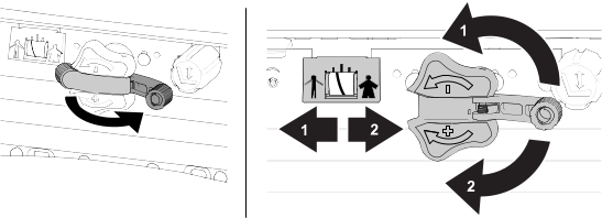
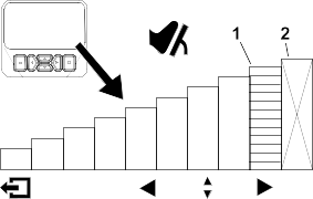
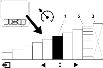
Overview of the Virtual Pedal Stop (VPS) Feature
The virtual pedal stop (VPS) feature allows you to temporarily set a maximum traction speed that is less than the password-protected
supervisor maximum traction speed.
To temporarily set the maximum speed of the machine, press the traction pedal fully forward. You can set a separate speed
for the mow range and transport range.
- To access this feature, press the up or down navigation button from the main screen.
Note: This feature reverts back to the supervisor maximum speed settings when the key is switched off.
G462150s
-
Indicates the maximum traction speed (pedal stop)
-
This speed is locked out under the protected PIN menu.
- This feature allows you to customize the speed settings for your comfort level, or to customize the speed settings to fit
the application.
- Whenever the maximum traction speed is changed via the supervisor maximum speed settings or Virtual Pedal Stop, the traction
pedal is automatically reprogrammed to use the full pedal stroke between neutral and the new maximum speed. This means the
operator gains more precise control of the traction speed at lower maximum speed settings.
Tips for Using Virtual Pedal Stop (VPS)
- Set the max speed temporarily lower for mowing the cleanup pass on the fairway.
- Set the max speed temporarily lower for improved control operating in or near the maintenance shop.
- Set the max speed temporarily lower for improved control loading the machine onto a trailer.
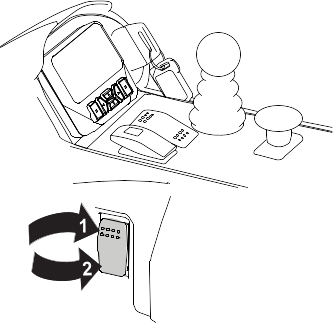
Cruise Control
Cruise Control Operation
The cruise-control switch locks in the cruise control to maintain the desired ground speed. Pressing the rear of the switch turns the cruise control
off, the middle position of the switch enables the cruise-control function, and the front of the switch sets the desired ground
speed.
After the cruise control switch is enabled and the speed is set, use the InfoCenter display to adjust the speed setting of
the cruise control.
To disengage the cruise control use the following:
- When in transport range, press the reverse traction pedal, engage the parking brake, or press the cruise control switch to
the Off position.
- When in mow range, press the reverse traction pedal, engage the parking brake, disengage the PTO, or press the cruise control
switch to the Off position.
Note: Disengaging cruise control results in the machine dynamically braking to a stop. If you would like to disengage cruise control
but continue driving, press the traction pedal and then disengage the cruise control for a smooth transition from cruise control
to manual speed control.
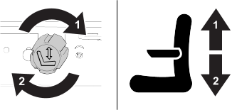
Adjusting the Cruise Control Speed
-
Enable the cruise control switch on the console.
-
Use the InfoCenter display to adjust the speed setting of the cruise control.
G462143s
-
Indicates the cruise control speed
-
Indicates the maximum traction speed (pedal stop)
-
This speed is locked out under the protected PIN menu.
Tips for Using the Cruise Control
- Set a cruising speed for long distances without many obstacles.
- On rough terrain, use the InfoCenter display to control the speed.
- Use the cruise control for turnarounds as follows:
-
While mowing, set a safe, comfortable speed for turning around at the end of mowing passes.
-
Press the traction pedal to increase the speed for mowing during the mowing pass.
-
Take your foot off the pedal when turning around for the next mowing pass.
-
The machine will slow down to the low cruise control setting, allowing you to make an efficient turnaround at a constant speed.
-
After turning around, use the traction pedal to increase the machine speed back up for the next mowing pass.
Overview of the Acceleration Mode
This feature determines how quickly the machine changes traction speed when the traction pedal is not in the Neutral position.
Note: If you take your foot off the traction pedal, allowing it to return to the Neutral position while the machine is moving, the braking profile is engaged. The braking profile is always the same and cannot be
customized by the acceleration mode feature.
Enter the protected menus on the InfoCenter display to change the acceleration mode. The acceleration mode has the following
3 positions:
- Low—least aggressive acceleration and deceleration
- Medium (default)—medium acceleration and deceleration
- High—most aggressive acceleration and deceleration
Overview of the Warm-Up Mode
When starting the machine in cold weather, warm-up mode limits the engine speed to low idle for a short period after the engine
is started, preventing potential component damage from operating the machine with cold oil.
A snowflake icon  on the display screen denotes when warm-up mode is active. Do not operate the machine until after the warm-up period.
Overview of Toro Smart Power™
With Smart Power, the operator does not have to listen to the engine speed in heavy load conditions. Smart Power prevents
the engine from bogging down in heavy cutting conditions by automatically controlling the machine speed and optimizing cutting
performance.
Note: By default, the Smart Power feature is On.
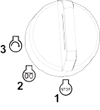
Starting the Engine
The fuel system automatically bleeds itself before starting the engine if you are starting the engine for the first time,
the engine has shut off due to lack of fuel, or you have performed maintenance on the fuel system.
-
Sit on the seat, keep your foot off the traction pedal so that it is in Neutral, engage the parking brake, and ensure that the PTO switch is not engaged.
-
Turn the key to the On/Preheat position.
An automatic timer controls the glow plug preheat for 6 seconds.
-
After preheating the glow plugs, turn the key to the Start position.
Note: Crank the engine for no longer than 15 seconds. Release the key when the engine starts. If additional preheating is required,
turn the key to the Off position and then to the On/Preheat position. Repeat this process as required.
-
Run the engine at low idle speed until it warms up.
Shutting Off the Engine
-
Move all controls to Neutral, engage the parking brake, and allow the engine to reach low idle speed.
-
Turn the key to the Off position and remove it from the switch.
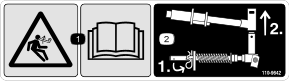
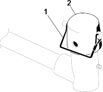
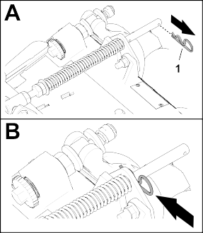
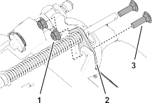
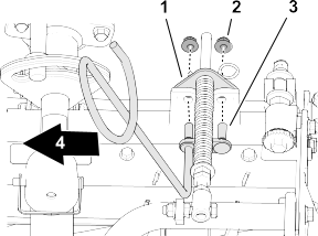
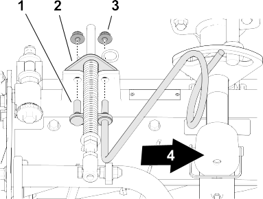
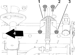
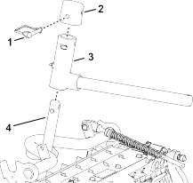
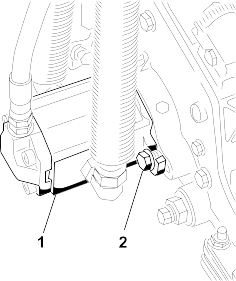
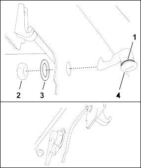
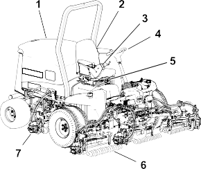
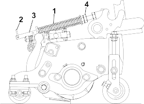
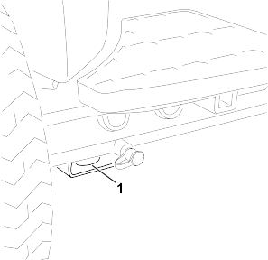
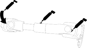
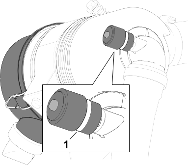
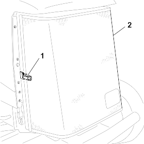
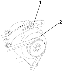
Adjusting the Turf-Compensation Spring
The turf-compensation spring transfers weight from the front to the rear roller. This helps to reduce a wave pattern in the turf, also known as marcelling
or bobbing.
Make spring adjustments with the cutting unit mounted to the traction unit, pointing straight ahead and lowered to the ground.
-
Make sure that the hairpin cotter  is installed in the rear hole in the spring rod
  .
.
-
Tighten the hex nuts  on the front end of the spring rod until the compressed length of the spring is 12.7 cm (5 inches) for 5-inch cutting units
or 15.9 cm (6.25 inches) for 7-inch cutting units.
on the front end of the spring rod until the compressed length of the spring is 12.7 cm (5 inches) for 5-inch cutting units
or 15.9 cm (6.25 inches) for 7-inch cutting units.
Note: When operating on rough terrain, decrease the spring length by 12.7 mm (1/2 inch). This slightly decreases the ground following.
Cutting Grass with the Machine
-
Disengage the parking brake, disengage the PTO, and raise the cutting units.
-
Drive the machine to the mowing area.
-
Park the machine approximately 6 m (20 ft) off the fairway, facing the intended mowing direction.
-
Lower the cutting units completely with the lift/lower control lever.
-
Engage the PTO.
Note: The cutting units will not start.
Note: The engine speed automatically rises to high idle when you lower the cutting units and activate the PTO switch.
-
Tap the lift/lower control lever rearward to lift the cutting units to the turnaround position.
Note: Tapping the lift/lower control lever without holding it raises the cutting units to the turnaround position and stops the
rotation of the reels until the cutting units are lowered.
-
Using the traction pedal, approach the mowing area slowly.
-
Once you reach the edge of the mowing area to start mowing, lower the cutting units with the lift/lower control lever.
Note: Practice to ensure the cutting units do not lower early or mow an unintended area.
-
Complete the mowing pass.
-
When nearing the opposite edge of the fairway (prior to reaching the edge of the mowing area), tap the lift/lower control
lever rearward to lift the cutting units to the turnaround position.
-
Perform a tear-shaped turn to quickly line up for your next pass.
-
Press the lift/lower control lever to automatically lower the cutting units from the turnaround position and continue mowing.
-
After mowing the desired area, follow the perimeter of the area to complete the cleanup mow pass. This will ensure that all
of the turf along the edge of the fairway where the cutting units were being lifted and lowered is uniformly cut.
Note: Use the Virtual Pedal Stop (VPS) to temporarily set a lower maximum speed to improve operating control while completing the
cleanup pass.
Understanding the Diesel-Particulate Filter and Regeneration
The diesel-particulate filter (DPF) removes soot from the engine exhaust.
The DPF regeneration process uses heat from the engine exhaust that is increased by the catalyst to convert accumulated soot
into ash.
To keep the DPF clean, remember the following:
- Run the engine at full engine speed when possible to promote DPF self-cleaning.
- Use the correct engine oil.
- Minimize the amount of time that you idle the engine.
- Use only ultra low sulfur diesel fuel.
Operate and maintain your machine with the function of the DPF in mind. Engine under load generally produces adequate exhaust
temperature for DPF regeneration.
Minimize the amount of time that you idle the engine or operate the engine at low-engine speed to help reduce the accumulation
of soot in the DPF.
|
Caution |
|
The exhaust temperature is hot (approximately 600°C (1,112°F) during DPF regeneration. Hot exhaust gas can harm you or other
people.
- Do not operate the engine in an enclosed area.
- Ensure that there are no flammable materials around the exhaust system.
- Ensure that the hot exhaust gas does not contact surfaces that may be damaged by heat.
- Do not touch a hot exhaust system component.
- Do not stand near or around the exhaust pipe of the machine.
Understanding the Regeneration Icons
|
|
A parked or recovery regeneration is requested.
Perform the regeneration immediately.
|
| |
|
|
A regeneration is acknowledged and the request is processing.
|
|
|
A regeneration is in progress and the exhaust temperature is elevated.
|
|
|
NOx control system malfunction; the machine requires service.
|
Types of Diesel Particulate Filter Regeneration
Types of diesel particulate filter regeneration that are performed while the machine is operating:
|
Passive
|
Occurs during normal operation of the machine at high-engine speed or high-engine load
|
- The InfoCenter does not display an icon indicating passive regeneration.
- During passive regeneration, the DPF processes high-heat exhaust gasses, oxidizing harmful emissions, and burning soot to
ash.
|
|
Assist
|
Occurs because of low-engine speed, low-engine load, or after the computer detects the DPF is becoming obstructed with soot
|
- The InfoCenter does not display an icon indicating assist regeneration.
- During assist regeneration, the engine computer adjusts the engine settings to raise the exhaust temperature.
|
|
Reset
|
Occurs every 100 hours
Also occurs if normal engine operation surpasses the allowed soot accumulation amount within the filter
|
- When the high exhaust-temperature icon
 is displayed in the InfoCenter, a regeneration is in progress. is displayed in the InfoCenter, a regeneration is in progress.
- During reset regeneration, the engine computer maintains an elevated engine speed to ensure filter regeneration.
|
| |
Types of diesel particulate filter regeneration that require you to park the machine:
|
Parked
|
Occurs because the computer determines that the automatic DPF cleaning has not been sufficient.
Also occurs because you initiate a parked regeneration
May occur because the inhibit regen has been initiated and has disabled the automatic DPF cleaning from occuring
May result from using the incorrect fuel or engine oil
|
- When the reset-standby/parked or recovery regeneration icon
 or a regeneration is requested. or a regeneration is requested.
- Perform the parked regeneration as soon as possible to avoid needing a recovery regeneration.
- A parked regeneration requires 30 to 60 minutes to complete.
- You must have at least a 1/4 tank of fuel in the tank.
- You must park the machine to perform a parked regeneration.
|
| |
|
Recovery
|
Occurs because the request for parked recovery has been ignored, allowing the DPF to be critically plugged
|
- When the reset-standby/parked or recovery regeneration icon a recovery regeneration is requested.
- A recovery regeneration requires up to 3 hours to complete.
- You must have at least a 1/2 tank of fuel in the machine.
- You must park the machine to perform a recovery regeneration.
|
Using the DPF Regeneration Menus
Accessing the DPF Regeneration Menus
-
From the Main Menu, scroll down to Service and press the select button.
-
In Service, scroll to DPF Regeneration and press the select button.
-
Select the regeneration function you need.
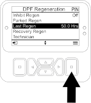
Time Since Last Regeneration
-
Access the DPF Regeneration menu, and scroll to Last Regen.
-
Select the Last Regen entry.
-
Use the Last Regen field to determine how many hours you have run the engine since the last reset, parked, or recovery regeneration.
-
Select the back button to return to the DPF Regeneration menu.
Setting the Inhibit Regen
Reset Regeneration Only
A reset regeneration produces elevated engine exhaust. If you are operating the machine around trees, brush, tall grass, or
other temperature-sensitive plants or materials, you can use the Inhibit Regen setting to prevent the engine computer from performing a reset regeneration.
Note: The Inhibit Regen option is always used when maintenance is being performed on the machine in an enclosed area.
Note: If you set the InfoCenter to inhibit regeneration, the InfoCenter displays an advisory every 15 minutes while the engine requests
a reset regeneration.
When you shut off the engine and start it again, the inhibit regen setting defaults to Off.
-
Access the DPF Regeneration menu, and scroll down to Inhibit Regen.
-
Select the Inhibit Regen entry.
-
Change the inhibit regeneration setting from Off to On.
Preparing to Perform a Parked or Recovery Regeneration
-
Ensure that the machine has fuel in the tank for the type of regeneration you are performing:
- Parked Regeneration: Ensure that you have 1/4 tank of fuel before performing the parked regeneration.
- Recovery Regeneration: Ensure that you have 1/2 tank of fuel before performing the recovery regeneration.
-
Move the machine outside to an area away from combustible materials or items that may be damaged by heat.
-
Park the machine on a level surface, move all controls to Neutral, disengage the PTO, and lower the cutting units.
-
Engage the parking brake and allow the engine to reach low idle speed.
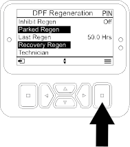
Performing a Parked or Recovery Regeneration
When a parked regeneration is requested by the engine computer, follow the messages on the InfoCenter.
The computer of the machine cancels DPF regeneration if you increase the engine speed from low idle or release the parking
brake.
-
Access the DPF Regeneration menu, and scroll down to Parked Regen or Recovery Regen.
-
Select the Parked Regen entry or the Recovery Regen entry.
Note: Initiating a recovery regeneration requires you to enter the correct PIN code.
-
At the Regen Parameters screen, verify that you have 1/4 tank of fuel if you are performing the parked regeneration or 1/2 tank of fuel if you are
performing the recovery regeneration. Verify that the parking brake is engaged and the engine speed is set to low idle. Press
the select button to continue.
-
At the Initiate DPF Regen screen, select the next button to continue.
-
The InfoCenter displays the Initiating DPF Regen message.
Note: If needed, press the cancel icon to cancel the regeneration process.
-
The InfoCenter displays the time to complete message.
-
The InfoCenter displays the home screen and the regeneration acknowledge icon appears .
Note: While the DPF regeneration runs, the InfoCenter displays the high exhaust-temperature icon .
-
When the engine computer completes a parked or recovery regeneration, the InfoCenter displays an advisory. Press any button
to exit to the home screen.
Note: If the regeneration fails to complete, follow the advisory and press any button to exit to the home screen.
Canceling a Parked or Recovery Regeneration
Use the Parked Regen Cancel or Recovery Regen Cancel setting to cancel a running parked or recovery regeneration process.
-
Access the DPF Regeneration menu, scroll to Parked Regen or Recovery Regen.
-
Press the select button to cancel a Parked Regen or a Recovery Regen.
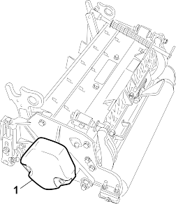
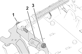
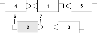
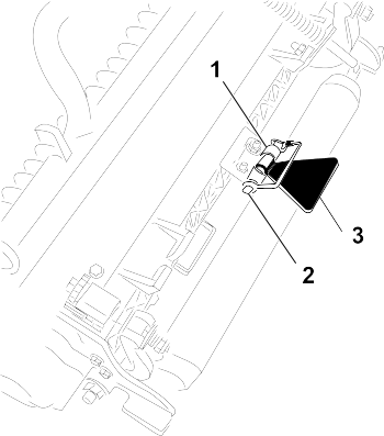
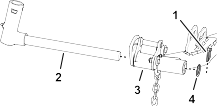
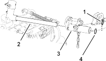
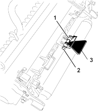
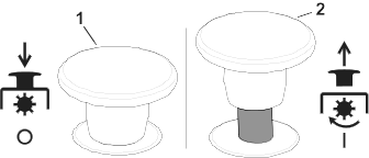
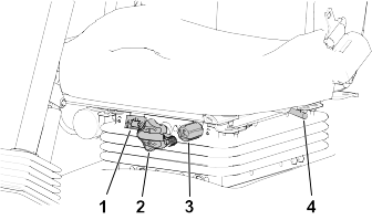
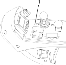
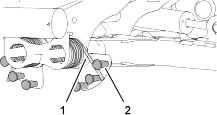
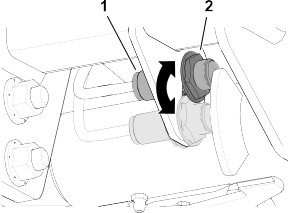
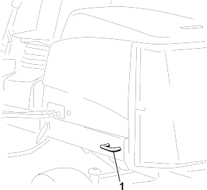
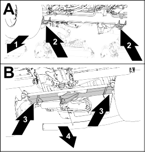
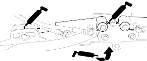
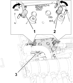
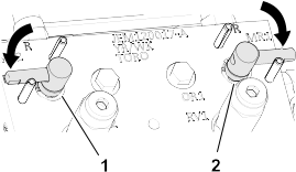
Adjusting the Lift-Arm Counterbalance
Rear Cutting Units
|
Caution |
|
The springs are under tension, and adjusting them could result in minor or moderate personal injury.
Use caution when adjusting the springs.
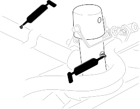
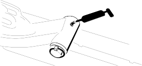
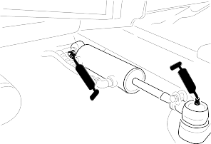
Adjust the amount of counterbalance force applied to the rear cutting-units to help compensate for different turf conditions,
and to maintain a uniform height of cut in rough conditions or in areas of thatch buildup.
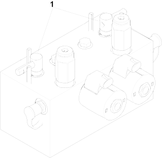
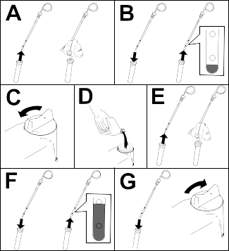
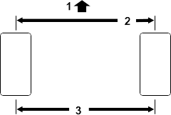
Adjust counterbalance force of each torsion spring to 1 of 4 settings. Each increment increases or decreases the counterbalance
force on the cutting unit by 2.3 kg (5 lb). You can position the springs at the back side of the first spring actuator to
remove all counterbalance (fourth position).
Note: To remove all counterbalance force, position the long leg of the torsion spring above the shouldered stud.
-
Park the machine on a level surface, lower the cutting units, shut off the engine, engage the parking brake, and remove the
key.
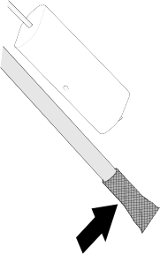
-
Insert the long end of the counterbalance spring into a tube or similar object, and pivot the spring around the shouldered stud to the desired position.
-
Repeat step 2 for the other counterbalance spring.
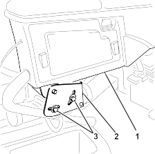
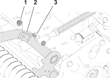
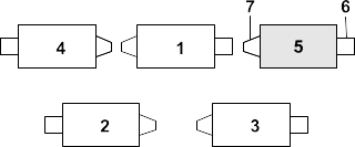
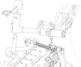
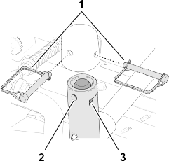
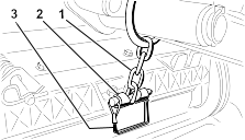
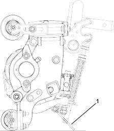
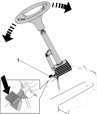
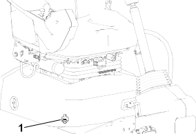
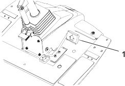
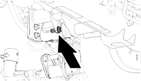
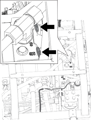
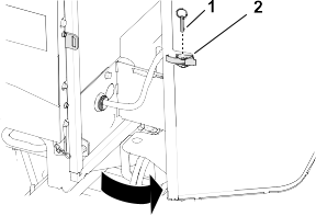
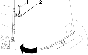
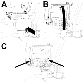
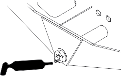
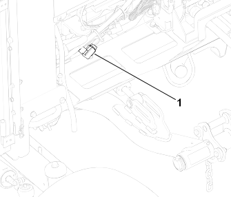
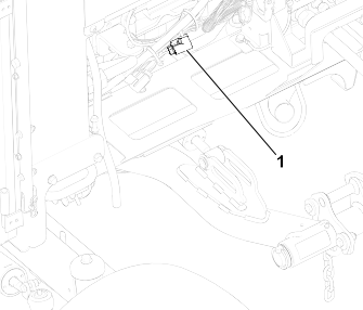
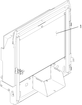
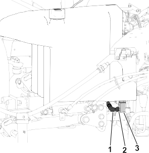
Adjusting the Lift-Arm Turnaround Position
-
Park the machine on a level surface, lower the cutting units, shut off the engine, engage the parking brake, and remove the
key.
-
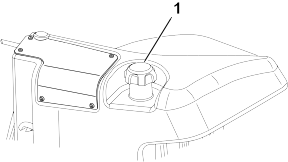
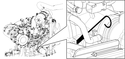
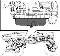
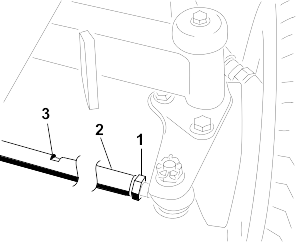
Locate the lift-arm switch underneath the hydraulic tank and inboard of the cutting unit #5 lift arm.
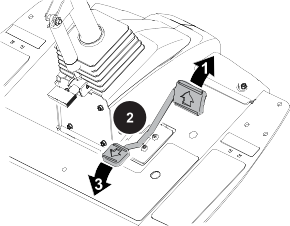
-
Loosen the jam nut that secures lift-arm switch to the switch plate .
-
Adjust the lift-arm switch as follows:
- To increase the lift-arm turnaround height, move the switch down.
- To decrease the lift-arm turnaround height, move the switch up.
Maintain an air gap of 1.0 to 2.5 mm (0.040 to 0.100 inches) between the switch and the lift-arm trigger. The LED light on
the switch verifies proper function of the switch.
-
Torque the jam nuts to 20 +/- 2 N∙m (15 +/- 1.5 ft-lb).
Do not overtorque the jam nuts; otherwise, you may damage the sensor.
Setting the Reel Speed
It is important that proper reel speeds are used for your mowing application.
- Reel speeds that are too slow may result in a wave pattern in the turf, also known as clip marks, marcelling, or bobbing.
If this is observed, try increasing the reel speeds or reducing the mowing speed.
- Reel speeds that are too fast may result in turf damage and/or premature wear of the reels, bedknives, and other mechanical
components.
To adjust the reel speed manually, complete the following:
-
In Machine Settings, enter the blade count, mow speed, and HOC to calculate the proper reel speed.
-
If further adjustments are required, in Machine Settings , scroll down to Front Reel Speed, Rear Reel Speed, or both.
-
Press the right navigation button to change the reel speed value. As the speed setting is changed, the display continues to
show the calculated reel speed based on blade count, mow speed, and HOC, but the new value is also shown.
Note: You may need to increase or decrease the reel speed to compensate for varying turf conditions.
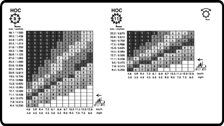
5 inch (127 mm) Reel Speed Chart
G439055
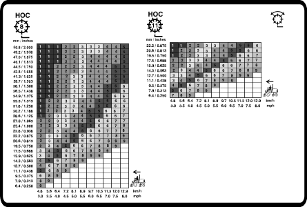
7 inch (178 mm) Reel Speed Chart
G439056
Overview of the Indicator Lights
- Flashing red—active fault
- Solid red—active advisory
- Solid blue—calibration/dialog messages
- Solid green—normal operation
Operating Tips
Overview of the Warning System
If a warning light comes on during operation, stop the machine immediately and correct the problem before continuing operation.
Serious damage could occur if you operate the machine with a malfunction.
Overview of Mowing Patterns
This is the most effective method to prevent washboarding.
Change mowing patterns often to minimize a poor after-cut appearance from repeatedly mowing in the same direction.
Proper Mowing Techniques
- To achieve the professional straight-line cut and striping that is desirable for some applications, find a tree or other object
in the distance and drive straight toward it.
- Maintain reel and bedknife sharpness.
- Maintain proper reel to bedknife clearance. Use light contact.
- Follow and maintain the 1/3rd rule (cut only 1/3 of the grass blade at a time).
- Set reel speed and traction speed to obtain the desired clip length.
- When mowing in wet conditions, open the rear shield of the cutting unit.
Scalping, Circle Cutting, and Verticutting
- Scalping/Circle Cutting
- Scalping and circle cutting are considered severe applications. Dedicate reels specifically to these applications.
- Follow and maintain the 1/3rd rule (cut only 1/3 of the grass blade at a time).
- Verticutting
- For 5-inch verticutters, set the verticutter blade depth to 1/8 inch or less. For 7-inch verticutters, set the blade depth
to 1/4 inch or less.
- Ensure that the cutting-unit blades are sharp, adjusted correctly, and that none of the blades are bent. Dull and bent blades
require more power.
- Adding more blades to reduce the blade spacing increases power consumption.
- Best Practices for Scalping, Circle Cutting, and Verticutting
- Open the rear cutting-unit shields.
- Recommended maximum mowing speed is 6 km/h (4 mph).
- Set the reel speeds to setting 6.
Note: Higher reel speed settings result in less torque. When scalping, better performance and efficiency is achieved at lower reel
speed settings.
- Do not use Economy Mode.
- Use the InfoCenter display to monitor both engine coolant and generator temperatures.
- Frequently check the rear radiator screen and the air cleaner air inlet screen above the radiator for chaff build up.
- Smart Power progressively limits the maximum mowing speeds as the generator and reel motors approach their temperature limits,
optimizing productivity by preventing the components from overheating.
- If the engine, generator, or reel motors overheat, park the machine in a shaded area with good air flow to let the components
cool.
Maintaining the Machine after Mowing
Complete the following steps after mowing:
-
Thoroughly wash the machine with a garden hose with no nozzle to avoid contamination and damage to the seals and bearings
caused by excessive water pressure.
-
Ensure that the radiator and oil cooler are kept free of dirt or grass clippings.
-
Inspect the machine for possible hydraulic-fluid leaks, damage, or wear to the hydraulic and mechanical components, and check
the cutting-unit blades for sharpness.
Transporting the Machine
Disengage the PTO and raise the cutting units to the Transport position. Be careful when driving between objects so you do not accidentally damage the machine or cutting units. Use extra
care when operating the machine on slopes. Drive slowly and avoid sharp turns on slopes to prevent rollovers. Lower the cutting
units when going downhill for steering control.