
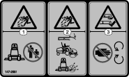
 , which means Caution, Warning,
or Danger—personal safety instruction. Failure to comply with
these instructions may result in personal injury or death.
, which means Caution, Warning,
or Danger—personal safety instruction. Failure to comply with
these instructions may result in personal injury or death.


Maintenance
Note: Determine the left and right sides of the machine from the normal operating position.
Recommended Maintenance Schedule(s)
| Maintenance Service Interval | Maintenance Procedure |
|---|---|
| Before each use or daily |
|
| Every 50 hours |
|
Greasing the Castor-Arm Bushings
| Maintenance Service Interval | Maintenance Procedure |
|---|---|
| Before each use or daily |
|
| Every 50 hours |
|
The machine has grease fittings that you must lubricate regularly with No. 2 lithium grease.
-
Park the machine on a level surface, lower the cutting unit, shut off the machine, remove the key, and turn the battery-disconnect switch to the OFF position.
-
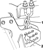
Lubricate the castor-arm bushings (Figure 17).
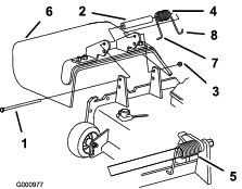
Removing the Cutting Unit from the Traction Unit
-
Park the machine on a level surface with the cutting unit raised.
-
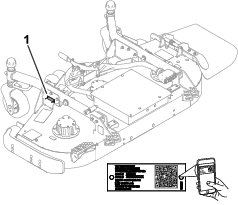
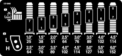
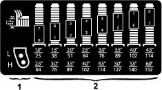
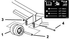
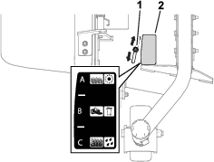
Remove the height-of-cut pins (Figure 18) from the cutting-unit side plates.
-
Lower the cutting unit, shut off the machine, and remove the key.
-
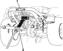
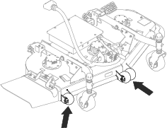
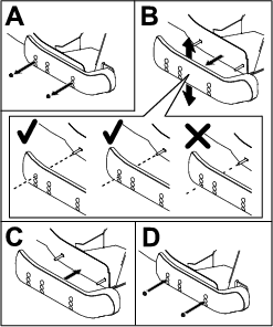
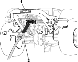
Remove the bolts and washers that secure the lift arms to the castor arms (Figure 19).
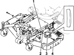
-
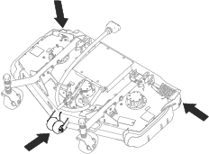
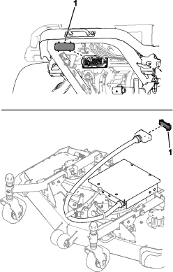
Disconnect the cutting-unit connector from the machine connector (Figure 20).
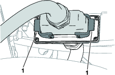
-
Install a cover to the cutting-unit connector and the machine connector (Figure 21).
Servicing the Bushings in the Castor Arms
The castor arms have bushings pressed into the top and bottom of the tube, and after many hours of operation, the bushings wear.
To check the bushings, move the castor fork back and forth and from side to side. If the castor spindle is loose inside the bushings, the bushings are worn; replace them.
-
Park the machine on a level surface, lower the cutting unit, shut off the machine, remove the key, and turn the battery-disconnect switch to the OFF position.
-
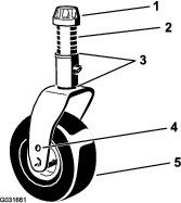
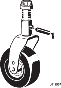
Remove the tensioning cap, spacer(s), and thrust washer from the top of the castor spindle.
-
Pull the castor spindle out of the mounting tube. Allow the thrust washer and spacer(s) to remain on the bottom of the spindle.
-
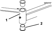
Insert a pin punch into the top or bottom of the mounting tube and drive the bushing out of the tube (Figure 22). Also, drive the other bushing out of the tube. Clean the inside of the tubes to remove dirt.
-
Apply grease to the inside and outside of the new bushings. Use a hammer and flat plate to drive the bushings into the mounting tube.
-
Inspect the castor spindle for wear and replace it if damaged.
-
Push the castor spindle through the bushings and mounting tube, slide the thrust washer and spacer(s) onto the spindle, and install the tensioning cap on the castor spindle.
Servicing the Cutting Blades
Blade Safety
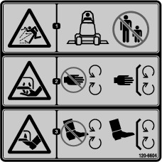
A worn or damaged blade can break, and a piece of the blade could be thrown toward you or bystanders, resulting in serious personal injury or death.
-
Inspect the blade periodically for wear or damage.
-
Use care when checking the blades. Wrap the blades or wear gloves, and use caution when servicing the blades. Only replace or sharpen the blades; never straighten or weld them.
Checking for a Bent Blade
After striking a foreign object, inspect the machine for damage and make repairs before starting and operating the equipment.
-
Park the machine on a level surface, raise the cutting unit to the TRANSPORT position, shut off the machine, remove the key, and turn the battery-disconnect switch to the OFF position.
-
Raise the cutting unit to the SERVICE position; refer to your traction unit Operator’s Manual.
-
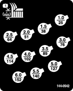
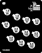
Rotate the blade until the ends face forward and backward and measure from the inside of the cutting unit to the cutting edge at the front of the blade (Figure 23).
Note: Remember this dimension.

-
Rotate the opposite end of the blade forward and measure between the cutting unit and cutting edge of the blade at the same position as in step 3.
Note: The difference between the dimensions obtained in steps 3 and 4 must not exceed 3 mm (1/8 inch). If the dimension exceeds 3 mm (1/8 inch), the blade is bent and must be replaced; refer to Removing and Installing the Cutting-Unit Blade(s).
Removing and Installing the Cutting-Unit Blade(s)
Replace the blade if it hits a solid object, is out of balance, or is bent. Always use genuine Toro replacement blades to ensure safety and optimum performance.
-
Park the machine on a level surface, raise the cutting unit to the TRANSPORT position, shut off the machine, remove the key, and turn the battery-disconnect switch to the OFF position.
-
Raise the cutting unit to the SERVICE position; refer to your traction unit Operator’s Manual.
-
Place a wrench on the flat of the blade retainer or hold the blade end using a rag or thickly padded glove.
-
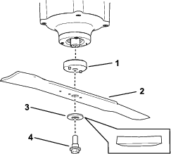
Remove the blade bolt, washer, and blade from the spindle shaft.
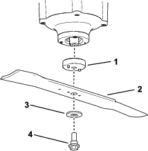
-
Install the blade to the shaft.
Ensure that the washer is oriented as shown in Figure 25 to ensure proper cutting.
Warning
Operating a machine after incorrectly installing the blade assembly and/or not using genuine Toro blade and blade hardware could allow a blade or blade component to be thrown out from under the deck, resulting in serious injury or death.
Always install genuine Toro blades and blade hardware according to the instructions.
-
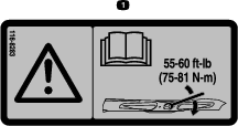
Place a wrench on the flat of the spindle shaft and torque the blade bolt to 75 to 81 N∙m (55 to 60 ft-lb).
Inspecting and Sharpening the Cutting Unit Blade(s)
| Maintenance Service Interval | Maintenance Procedure |
|---|---|
| Before each use or daily |
|
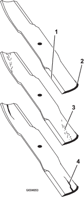
Both cutting edges and the sail, which is the turned-up portion opposite of the cutting edge, contribute to a good quality of cut.
Maintain sharp blades throughout the cutting season. Sharp blades create a clean cut without tearing or shredding the grass blades.
Check the blades for any wear or damage. The sail lifts the grass up straight, thereby producing an even cut and gradually wears down during operation.
-
Park the machine on a level surface, raise the cutting unit to the TRANSPORT position, shut off the machine, remove the key, and turn the battery-disconnect switch to the OFF position.
-
Raise the cutting unit to the SERVICE position; refer to your traction unit Operator’s Manual.
-
Examine the cutting ends of the blade carefully, especially where the flat and curved parts of the blade meet (Figure 26).
Note: Because sand and abrasive material can wear away the metal that connects the flat and curved parts of the blade, check the blade before using the mower. If you notice wear (Figure 26), replace the blade.
-
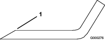
Examine the cutting edges of all of the blades and sharpen the cutting edges if they are dull or nicked (Figure 27).
Note: Sharpen only the top of the cutting edge and maintain the original cutting angle to ensure sharpness (Figure 27). The blade remains balanced if the same amount of metal is removed from both cutting edges.
Note: Remove the blades and sharpen them on a grinder. After sharpening the cutting edges, install the blade; refer to Removing and Installing the Cutting-Unit Blade(s).
Replacing the Grass Deflector
Warning
An uncovered discharge opening allows the machine to throw objects toward you or bystanders, which can result in serious injury. Contact with the blade can also occur.
-
Do not operate the machine unless you install a cover plate, a mulch plate, or a grass chute and catcher.
-
Ensure that the grass deflector is lowered.
-
Park the machine on a level surface, lower the cutting unit, shut off the machine, remove the key, and turn the battery-disconnect switch to the OFF position.
-
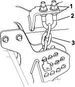
Remove the locknut, bolt, spring and spacer holding the deflector to the pivot brackets (Figure 28). Remove the damaged or worn grass deflector.
-
Place the spacer and spring onto grass deflector. Place the L-end of the spring behind the cutting unit edge.
Note: Ensure that the L-end of the spring is installed behind the cutting unit edge before installing the bolt as shown in Figure 28.
-
Install the bolt and nut. Place the J-hook end of the spring around the grass deflector (Figure 28).
Important: You must be able to lower the grass deflector into position. Lift the deflector up to test that it lowers into the full down position.
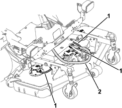
Checking the Electrical Cables
| Maintenance Service Interval | Maintenance Procedure |
|---|---|
| Before each use or daily |
|
Check the condition of the cutting-unit connector cable and the blade-motor cables (Figure 29) for damage or wear. Make all necessary repairs before operating the machine.
Cleaning under the Cutting Unit
| Maintenance Service Interval | Maintenance Procedure |
|---|---|
| Before each use or daily |
|
Remove the grass buildup under the cutting unit daily.
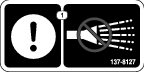
Important: Do not use a pressure washer and do not spray the electrical components on the top of the cutting unit directly with water, as you could damage the motors and other electric components.
Warning
Using compressed air improperly to clean the machine could result in serious injury.
-
Wear appropriate personal protective equipment, such as eye protection, hearing protection, and a dust mask.
-
Do not aim compressed air at any part of your body or at anyone else.
-
Refer to the manufacturer’s instructions for the air compressor for operating and safety information.
-
Park the machine on a level surface, raise the cutting unit to the TRANSPORT position, shut off the machine, remove the key, and turn the battery-disconnect switch to the OFF position.
-
Raise the cutting unit to the SERVICE position; refer to your traction unit Operator’s Manual.
-
Clean debris from under the cutting unit using compressed air or water.
Important: Do not use a pressure washer to clean the cutting unit.