Installation
Note: This kit is for installing rollers on one cutting unit. Please order Roller Kits for each cutting unit.
Modifying the Cutting Unit
Parts needed for this procedure:
| Template | 1 |
Caution
Using cutting tools without wearing the appropriate personal protective equipment (PPE), such as eye protection and work gloves, may result in minor or moderate injury.
Whenever you use cutting tools, always wear the appropriate PPE.
Note: If needed, remove the cutting units from the machine. If you do not remove the cutting units, lock the cutting units in the transport position.
-
Park the machine on a level surface, shut off the engine, chock the wheels or engage the parking brake if attached to a traction unit, and remove the key from the ignition switch.
-
Remove the existing rollers from the cutting unit.
-
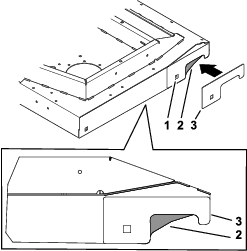
Align the template and install a carriage bolt (Figure 1).
Important: Ensure that the template is tight against the cutting unit. The template square hole should be aligned with the cutting-unit square hole.
-
Mark the area to be removed, remove the template, and remove the material from the cutting unit (Figure 1).
-
Repeat this procedure on the opposite side.
Installing the Decals
Parts needed for this procedure:
| Decal | 4 |
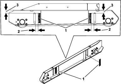
Install the decals onto each skid as shown in Figure 2.
-
Decal
-
28.6 mm (1-1/8 inches)
-
33.3 mm (1-5/16 inches)
Installing the Rollers
Parts needed for this procedure:
| Roller | 2 |
| Left skid | 1 |
| Right skid | 1 |
| Flat washer | 4 |
| Nut (11/32 inch) | 4 |
| Locknut | 4 |
| Dust cap | 4 |
| Tapered bearing | 4 |
| Flange nut (3/8 inch) | 16 |
| Hub assembly | 4 |
| Carriage bolt (3/8 x 1-1/4 inches) | 16 |
| Cotter pin | 4 |
| Grease fitting | 4 |
-
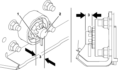
Install the grease fittings into the hub assemblies (Figure 3).
-
Pack the roller bearings full of grease.
-
Apply grease to bearing race and the inner part of the hub assemblies.
-
Install the hub assemblies to each skid with 16 carriage bolts (3/8 x 1-1/4 inches) and 16 carriage bolts (3/8 x 1-1/4 inches): refer to Figure 3.
-
Install a skid to the cutting unit.
-
Install the rollers to the assembled skid with 2 roller bearings, 2 flat washers, 2 nuts (11/32 inch), and 2 locknuts (Figure 3).

-
On one end of the roller shaft, install the nut and locknut until there is 9.5 mm (3/8 inch) between the face of the locknut and the end of the roller shaft (Figure 4).
-
Install the cotter pin after you adjust the locknut (Figure 3).
-
Install the rollers into the hubs on the opposite skid and secure the skid to the cutting unit.
-
Install the rollers to the assembled skid with 2 roller bearings, 2 flat washers, 2 nuts (11/32 inch), and 2 locknuts (Figure 3).
-
Install the nuts and locknuts until the bearings and hardware are seated in the hub.
-
Using a rolling torque wrench, set the rolling torque for the nut and locknut on both shafts to 1.3 to 1.7 N∙m (10 to 15 in-lb).
Note: If needed, rotate the locknuts a 1/4 turn to achieve the correct torque. Check the torque after you adjust the locknuts.
-
Install the cotter pins and ensure that all 4 cotter pins engage the locknuts (Figure 3).
-
If the cotter pins do not engage the locknuts, adjust the locknuts and check the rolling torque.
-
Grease the new hub assemblies.
-
Install the dust caps on each end of the rollers (Figure 3).