


Maintenance
Note: Determine the left and right sides of the machine from the normal operating position.
Recommended Maintenance Schedule(s)
| Maintenance Service Interval | Maintenance Procedure |
|---|---|
| After the first 8 hours |
|
| After each use |
|
| Every 25 hours |
|
| Every 50 hours |
|
| Every 100 hours |
|
Warning
If you leave the key in the ignition switch, someone could accidently start the engine and seriously injure you or other bystanders.
Remove the key from the ignition and disconnect the wire from the spark plug before you do any maintenance. Set the wire aside so that it does not accidentally contact the spark plug.
Warning
An engine can become hot while it operates. Severe burns can occur from contacting hot surfaces.
Allow the engine, especially the muffler, to cool before touching it.
Warning
Debris, such as leaves, grass, or brush can catch fire. A fire in the engine area can cause personal injury and property damage.
-
Keep the engine and muffler area free of debris accumulation.
-
Take care when opening the bagger cover to keep debris from falling onto the engine and muffler area.
-
Allow the machine to cool before storing it.
Preparing for Maintenance
Do the following steps before preforming maintenance on the machine:
-
Park the machine on a level surface.
-
Disengage the PTO, move the motion control levers to the neutral locked position, and set the parking brake.
-
Stop the engine, remove the key, and wait for all moving parts to stop before leaving the operating position.
-
Clean the mower of any debris on the deck or rear part of the mower to ease maintenance.
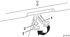
Cleaning the Hood Screen
| Maintenance Service Interval | Maintenance Procedure |
|---|---|
| After each use |
|
-
Disengage the power take off (PTO) and set the parking brake.
-
Turn off the engine, remove the key, and wait for all moving parts to stop before leaving the operating position.
-
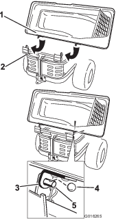
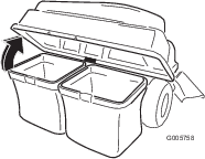
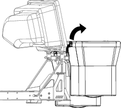
Open the bagger hood.
-
Clean the debris from the screen.
-
Close the bagger hood.
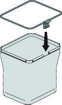
Cleaning the Bagger and Bags
| Maintenance Service Interval | Maintenance Procedure |
|---|---|
| After each use |
|
-
Wash the inside and outside of the bagger hood, bags, tube, and the underside of the mower.
Note: Use a mild automotive detergent to remove dirt.
-
Make sure that you remove matted grass from all parts.
-
After washing all parts, let them dry thoroughly.
Note: With all parts installed, start and run the machine for a minute to assist in drying.
Inspecting the Blower Belt
| Maintenance Service Interval | Maintenance Procedure |
|---|---|
| After the first 8 hours |
|
| Every 25 hours |
|
Check belts for cracks, frayed edges, burn marks or any other damage. Replace damaged belts.
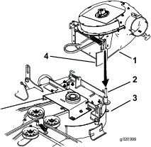
Replacing the Blower Belt
-
Disengage the PTO, move the motion control levers to the neutral locked position, and set the parking brake.
-
Stop the engine, remove the key, and wait for all moving parts to stop before leaving the operating position.
-
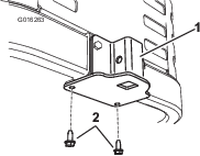
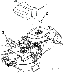
Remove the plastic belt cover.
-
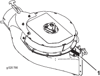
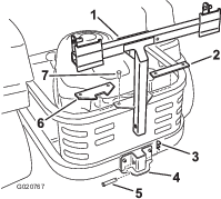
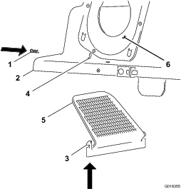
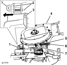
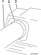
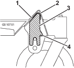
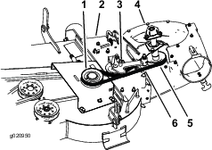
Pull back on the spring-loaded idler pulley to relieve the belt tension (Figure 29).
-
Remove the existing bagger belt from the mower-deck pulley.
-
Remove the blower from the mower deck.
-
Remove the existing bagger belt from the blower pulleys.
-
Install the new belt around the blower pulleys (Figure 29).
-
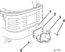
Install the blower onto the blower support.
-
Install the new belt around the mower-deck pulley (Figure 29).
-
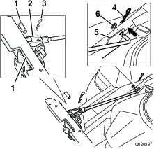
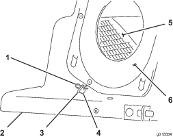
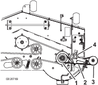
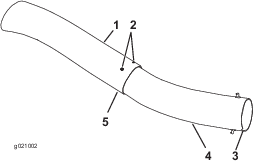
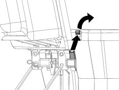
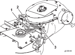
Install the spring onto the idler pulley post (Figure 30).
-
Stretch and install the spring onto the shoulder bolt (Figure 30).
-
Pull back on the spring loaded idler pulley and install the belt onto the spring loaded idler pulley (Figure 29).
Greasing the Idler Arm
| Maintenance Service Interval | Maintenance Procedure |
|---|---|
| Every 50 hours |
|
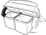
Inspecting the Bagger
| Maintenance Service Interval | Maintenance Procedure |
|---|---|
| After the first 8 hours |
|
| Every 100 hours |
|
-
Disengage the PTO, move the motion control levers to the neutral locked position, and set the parking brake.
-
Stop the engine, remove the key, and wait for all moving parts to stop before leaving the operating position.
-
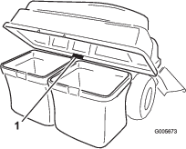
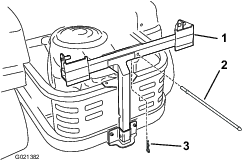
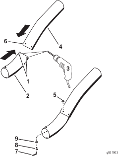
Check the upper tube, lower tube, bagger hood, and the blower assembly.
Note: Replace these parts if they are cracked or broken.
-
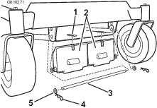
Check the bags, bagger frame, and screen.
Note: Replace any parts that are cracked or broken.
-
Tighten all nuts bolts and screws.
Inspecting the Mower Blades
-
Inspect the mower blades regularly and whenever a blade strikes a foreign object.
-
If blades are badly worn or damaged, install new blades. Refer to your machine Operator's Manual for complete blade maintenance.