Installation
Preparing the Machine
-
Park the machine on a level surface.
-
Engage the parking brake.
-
Lower the attachment.
-
Shut off the engine and remove the key.
-
Remove the cutting unit from the traction unit; refer to the traction unit Operator’s Manual.
Removing the Existing Idler Stop
-
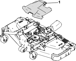
Remove the belt cover (Figure 1) from the top of the cutting unit and set the cover aside.
-
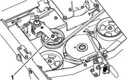
Using a socket wrench or similar tool, move the idler pulley (Figure 2) away from the drive belt to release the belt tension and allow the belt to slip off the idler pulley.
Caution
The spring is under heavy load and can cause personal injury.
Be careful when removing tension from the torsion spring of the idler arm.
-
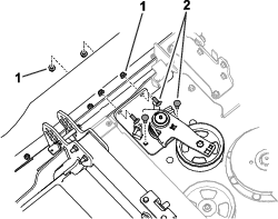
Remove the carriage bolts and nuts that secure the tensioner assembly to the cutting unit (Figure 3).
-
Secure the idler assembly in a vise by clamping on the idler pivot plate.
-
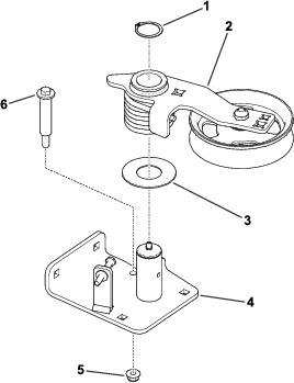
Remove the shoulder bolt from the idler pivot plate then unload the idler spring tension (Figure 4).
-
Remove the retaining ring that retains the idler arm to the idler pivot (Figure 4).
Installing the Idler Stop
Parts needed for this procedure:
| Idler pivot assembly | 1 |
| Carriage bolt (3/8 x 1 inch) | 2 |
| Carriage bolt (3/8 x 1-1/4 inches) | 2 |
| Shoulder bolt | 1 |
| Hex bolt | 1 |
| Flange nut (3/8 inch) | 5 |
| Flange nut (5/16 inch) | 2 |
-
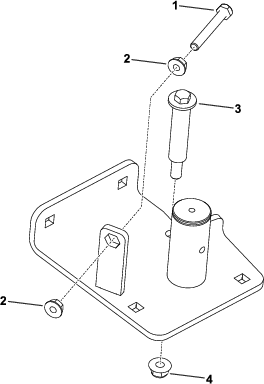
Use 2 flange nuts (5/16 inch) to secure the hex bolt to the new idler pivot assembly (Figure 5).
-
Use the retaining ring to secure the idler arm and spring to the idler pivot.
-
Secure the idler assembly in a vise by clamping on the idler pivot plate.
-
Use a 3/8-inch or 1/2-inch drive ratchet or breaker bar in the idler arm to move the idler arm (load the torsion spring) enough to install the shoulder bolt.
-
Install a flange nut (3/8 inch) and a shoulder bolt to the idler pivot plate (Figure 5).
Tighten the nut to 45 to 55 N·m (33 to 41 ft-lb) and release the idler arm.
-
Use 2 carriage bolts (3/8 x 1 inch), 2 carriage bolts (3/8 x 1-1/4 inches), and 4 flange nuts (3/8 inch) to secure the tensioner assembly to the cutting unit (Figure 6).
-
Install the drive belt around the idler pulley (Figure 7).
-
Install the belt cover.