Note: Determine the left and right sides of the machine from the normal operating position.
Installation
Preparing the Machine
-
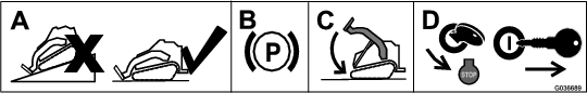
Park the machine on a level surface.
-
Engage the parking brake.
-
Lower the loader arms.
-
Shut off the engine and remove the key.
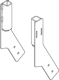
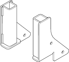
Selecting the Correct Shield Bracket
Note: Ensure that the correct bracket is selected for your machine.
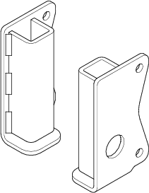
Installing the Shield Brackets
Parts needed for this procedure:
| Right shield bracket | 1 |
| Left shield bracket | 1 |
| Bolt (1/4 x 3/4 inch) | 4 |
| Locknut (1/4 inch) | 4 |
-
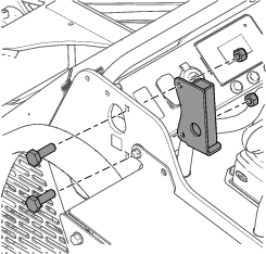
Measure in from the edges of the frame as illustrated in Figure and mark the locations of the holes for mounting the shield bracket on both sides of the machine.
Note: If the holes exist, skip to step 3.
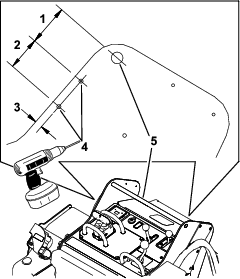
-
Drill a hole (9/32 inch) through the frame at each marked location.
-
Using the bracket selected in Selecting the Correct Shield Bracket, install the left shield bracket on the left frame using 2 bolts (1/4 x 3/4 inch) and 2 locknuts (1/4 inch) as shown in Figure 6 and Figure 7.
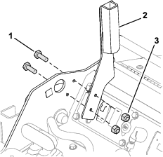
-
Install the right shield bracket on the right frame using 2 bolts (1/4 x 3/4 inch) and 2 locknuts (1/4 inch).
Assembling the Operator Shield
Parts needed for this procedure:
| Shield support | 2 |
| Shield | 1 |
| Bolt (1/4 x 1-1/2 inches) | 8 |
| Washer | 8 |
| Locknut (1/4 inch) | 8 |
-
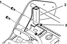
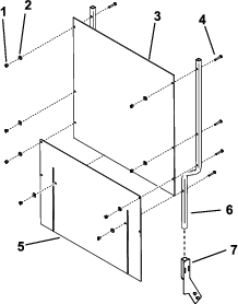
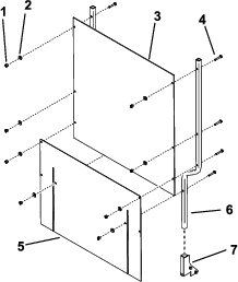
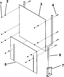
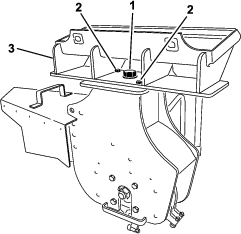
Assemble the shield and flexible skirt to the shield supports, as shown below using 8 bolts (1/4 x 1-1/2 inch), 8 washers, and 8 locknuts (1/4 inch).
-
Slide the shield supports into the pockets in the shield brackets on the traction unit.
Note: The skirt should drape over the engine or hood.
Replacing the Quick-Attach Assembly
Parts needed for this procedure:
| Quick-attach assembly | 1 |
-
Lay the stump grinder flat on the floor.
-
Place wood blocks under the body of the stump grinder so that the quick-attach plate is off the floor.
-
Remove the large bolt (1 x 2-1/4 inch), washer, nut (1 inch), 2 small bolts (1/2 x 1-1/2 inches), and 2 nuts (1/2 inch) securing the quick-attach assembly to the stump grinder (Figure 12). Remove the assembly.
-
Install the new quick-attach assembly to the stump grinder using the hardware you removed, as shown in Figure 12.
Note: The new quick-attach assembly has a wider hose loop.
-
Torque the large bolt (1 x 2-1/4 inch) to 406 N∙m (300 ft-lb), and torque the small bolts (1/2 x 1-1/2 inches) to 101 N∙m (75 ft-lb).
-
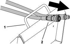
Route the hoses through the hose loop (Figure 13).