Installation
Preparing the Machine
-
Park the machine on a level surface.
-
Lower the cutting units.
-
Engage the parking brake.
-
Shut off the engine and remove the key.
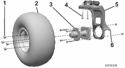
Removing the Existing Wheel
-
Raise the unit on the castor fork lift point (Figure 1).
-
Remove the wheel assembly from the wheel hub. Retain the lug nuts (Figure 1).
-
Remove the 4 bolts and 2 nuts securing the wheel hub to the castor fork (Figure 1). Discard all items.
-
Remove the 2 bolts and 2 nuts securing the vertical steering pivot to the castor fork (Figure 1). Discard these items.
Important: Do not loosen the 2 remaining bolts securing the spindle to the castor fork.
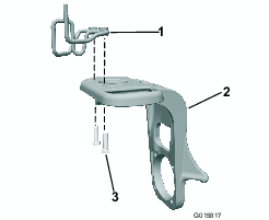
Installing the Wire-Form Hose Guide
Parts needed for this procedure:
| Wire form hose guide | 1 |
| Bolt (1/2 x 1-1/2 inches) | 2 |
-
Install the wire-form hose guide on top of the castor fork and secure it with 2 bolts (1/2 x 1-1/2 inches).
-
Torque the bolts to 75 ft-lb (101.7 N∙m).
Installing the Motor Assembly
Parts needed for this procedure:
| Bolt (1/2 x 2-1/2 inches) | 2 |
| Locknut | 4 |
| Wheel motor assembly | 1 |
| Hydraulic fittings | 2 |
| Socket-head bolt (1/2 x 3-3/4 inches) | 4 |
| Shim plate | 1 |
-
Install the 45° hydraulic fittings into the wheel motor and orient them approximately as shown in Figure 3. Leave the fittings loose.
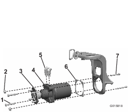
-
Install the wheel hub to the motor assembly and torque to 250 to 400 ft-lbs (339 to 540 N∙m).
-
Install the wheel-motor assembly and shim plate to the castor fork (placing the shim between the motor and castor fork) and secure it with 4 socket head bolts (1/2 x 3-3/4 inches), 2 bolts (1/2 x 2-1/2 inches), and 4 locknuts.
-
Torque the bolts to 75 ft-lb (101.7 N∙m).
Installing the Steel Lines
Parts needed for this procedure:
| Tube clamp | 2 |
| Hydraulic lines | 2 |
| Bolt (5/16 x 1-3/4 inches) | 1 |
| Cover plate | 1 |
-
Loosely install the steel hydraulic lines to the wheel motor fittings (Figure 4).
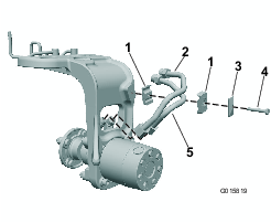
-
Install the tube clamp to the castor fork. Adjust this assembly for proper fit with the hydraulic fittings and tube clamps (Figure 4).
-
Secure the tube clamps with a cover plate and bolt (5/16 x 1-3/4 inches) as shown in Figure 4.
Important: Do not tighten fully until the last step.
-
Secure the tube fittings and hydraulic fittings. Use a back-up wrench to eliminate twisting on hard lines.
Installing the Hose Bracket
Parts needed for this procedure:
| Hose bracket | 1 |
| Bolt (5/16 x 7/8 inch) | 2 |
| Flange nut (5/16 inch) | 6 |
| Hose shield | 1 |
| Wire form | 1 |
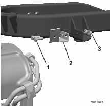
Gasoline-Powered Traction Units
Install the hose bracket to the frame and secure it with 2 bolts (5/16 x 7/8 inch) and 2 flange nuts (5/16 inch) as shown in Figure 5.
Diesel-Powered Traction Units
-
Install the wire form to the frame and secure it with 2 bolts (5/16 inch) and 2 nuts (Figure 6).
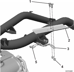
-
Install the hose shield to the wire form and secure it with 2 bolts and 2 nuts.
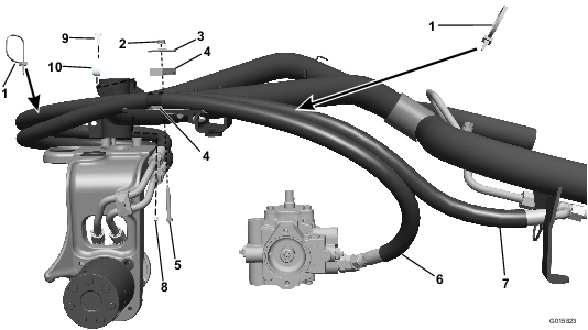
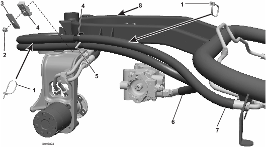
Installing the Traction Hoses
Parts needed for this procedure:
| 45° hydraulic fitting (1-1/16 inch, 12 tpi SAE end) | 1 |
| 45° hydraulic fitting (7/8 inch, 14 tpi SAE end) | 1 |
| Wire tie | 2 |
| Flange nut | 1 |
| Cover plate | 1 |
| Tube clamp | 1 |
| Bolt | 2 |
| Nut | 1 |
| R-clamp | 1 |
-
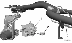
Disconnect the lower hydraulic pump hose from the pump and from the upper bulkhead tee fitting to the front motors. Discard this hose (Figure 7).
-
Gasoline-powered traction unit only: Remove the lower 90° hydraulic fitting from the pump and replace it with the appropriate 45° hydraulic fitting per the hydraulic pump on your machine:
-
Machines equipped with an Eaton pump: Install the fitting that has a 1-1/16 inch, 12 tpi SAE end.
-
Machines equipped with a Danfoss pump: Install the fitting that has a 7/8 inch, 14 tpi SAE end.
Leave the fitting loose, oriented up, and facing out (Figure 7).
-
-
Install the hose with straight fittings at both ends through the guide on the castor fork and attach it to the lower steel line. Attach the opposite end to the lower hydraulic-pump fitting (Figure 8 or Figure 9).
-
Install the remaining hose through hose guide and attach to upper steel line. Attach the opposite end to the upper tee fitting for front-wheel motor (Figure 8 or Figure 9).
-
Install both hose assemblies into the tube clamp at the hose cover split and attach it to the bracket. (Figure 8; or Figure 9).
-
Tighten the jam nuts on the motor fittings.
-
Install the tire and secure with the previously-removed lug nuts.
-
Rotate the castor fork and the adjust hose position for proper fit by flexing it through the hose guide and clamp.
-
Add the wire ties to the hose assemblies as shown (Figure 8 or Figure 9). Secure all hose ends, fittings, and clamps.
-
Rotate the castor fork fully in each direction and check for clearance with tire, frame, and tank.