Safety
Autosteer Safety
The GeoLink Autosteer system provides steering guidance control, when the proper conditions are met, but you are responsible for driving the machine and must remain alert and in complete control of the machine at all times.
When using the control console for assisted steering during spraying operation, ensure that you operate the machine with attention to the following:
-
The control console does not detect obstacles or hazards, keep the machine away from people, animals, buildings, and other structures.
-
Do not operate the machine near high-voltage power lines or other overhead obstacles.
-
Ensure that the operating area is clear of obstacles.
-
Know the position of the machine and the ground (field) conditions at all times.
-
Respond if satellite signals or the RTK correction is lost momentarily.
Note: When fallback mode is enabled, the system remains engaged if the RTK correction is lost and momentarily drops to float, estimated, or GPS. The system only disengages if the GPS signal is lost. Take manual control if the GPS signal is lost.
Take manual control of the machine if an obstacle appears in the path of the machine or if the machine moves off of the guideline.
Setup
Installing the Plus+1 Service Tool
Downloading the Software
-
Go to Gateway and click on Service Library.
-
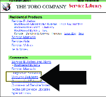
Select GeoLink Solutions.
-
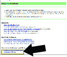
Select Autosteer Software.
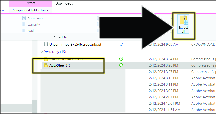
Note: The file saves to the Downloads directory of your laptop computer.
-
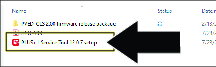
Select the download and click Extract all.
-
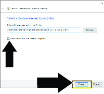
In the Extract Compressed dialog box, ensure that the check box is selected, and click the button .
Installing the Software and Driver Files
Important: The person installing the PLUS+1 Service tool must have administrative privileges on the laptop computer.
-
Double click the PLUS+1 ServiceTool 12.0.7 setup.exe file.
-
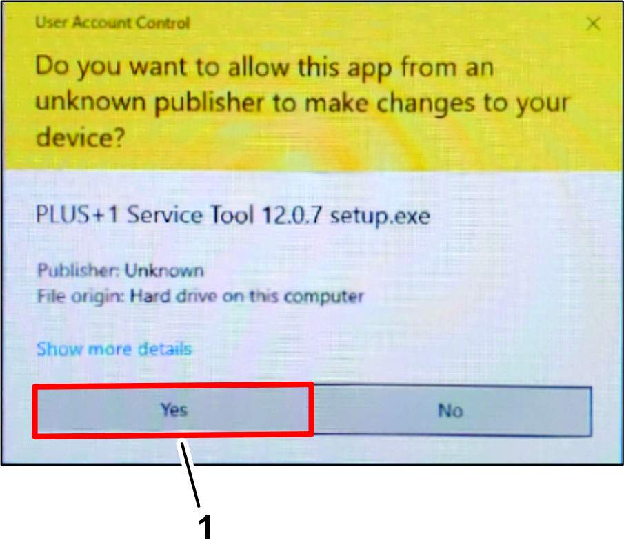
If the User Account Control dialog box displays, click the YES button (Figure 7).
-
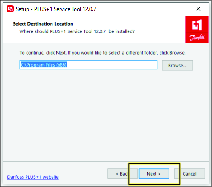
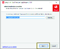
In the Select Destination Location dialog box, click the NEXT button.
-
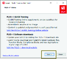
In the Plus+1 Online dialog box, click the NEXT button.
-
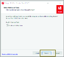
In the Select Additional Tasks dialog box, click the NEXT button.
-
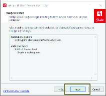
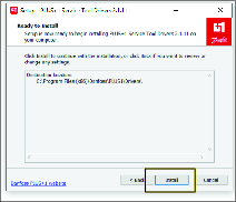
In the Ready to Install dialog box, click the INSTALL button.
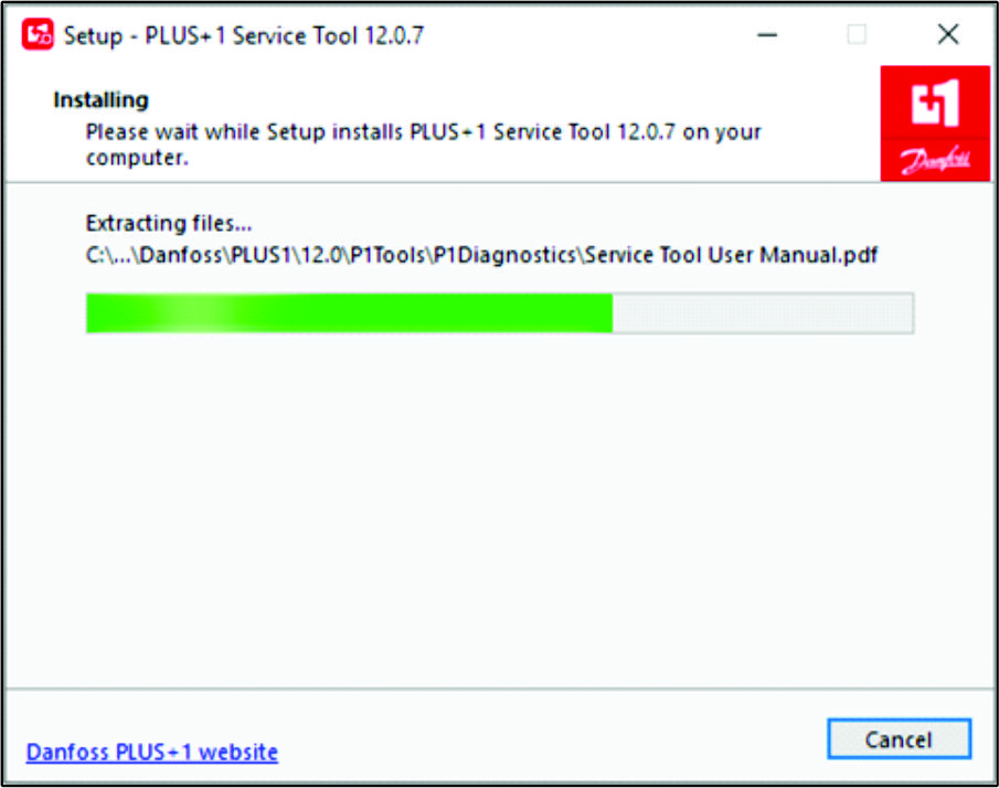
Note: The progress dialog box displays.
-
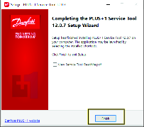
In the Completing Service Tool Setup Wizard dialog box, click the FINISHED button.
Installing the Drivers
-
In the Select Destination Location dialog box, click the NEXT button.
-
In the Ready to Install dialog box, click the INSTALL button.
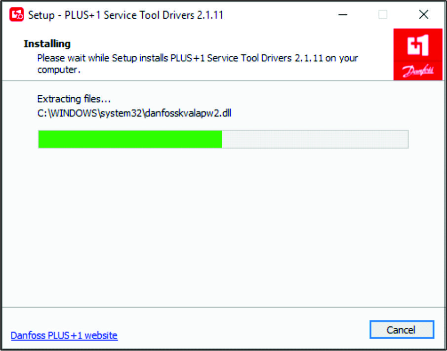
Note: The progress dialog box displays.
-
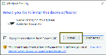
In the Would you like to install this device software dialog box, click the INSTALL button.
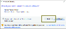
-
In the Would you like to install this device software dialog box, click the INSTALL button.
-
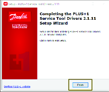
In the Completing Service Tool Drivers Setup Wizard dialog box, click the FINISHED button.
Installing the Service and Data Files
-
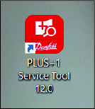
Double click on the Plus+1 Service Tool icon.
-
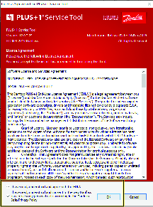
Read the license information, check the boxes noting you have read and agree to the agreement, and click OK.
-
Click OK on the confirmation screen.
-
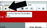
Click on the folder with magnifying glass icon to Scan for Service Application File.
-
Navigate to the Service tool folder in the PVED-CLS 2.00 firmware release package folder.
-
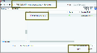
Click on PVED-CLS_2.00_rev_D and click OPEN.
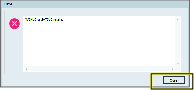
-
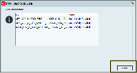
Click CLOSE if you receive this error. This is a passive error and will not effect the installation or use of this tool.
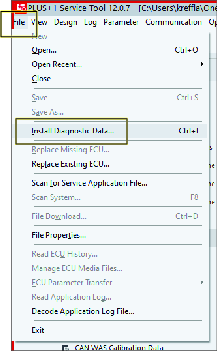
Installing the Diagnostic Data
-
Click the icon, and in the drop-down list, click the icon.
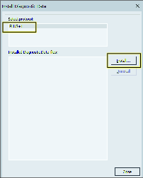
-
In the Install Diagnostic Data dialog box, click the PLUS+1 protocol icon, and press the icon.
-
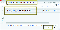
Navigate to the Diagnostic data files folder in the PVED-CLS 2.00 firmware release package folder.
-
Select all the files in this folder and click OK.
-
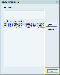
In the dialog box, click the icon.
-
In the dialog box, click the icon.
Selecting the Gateway Channel
-
Plug a Toro Diag cable into the USB port of the laptop computer and open the Plus+1 software program.
-
On the ribbon bar, click the Communication button.
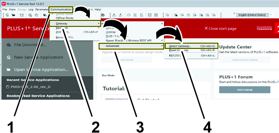
-
In the Communication drop-down menu, click the Gateway button.
-
In the Gateway drop-down menu, click the Advanced button.
-
In the Advanced drop-down menu, click the Select Gateway... button.
-
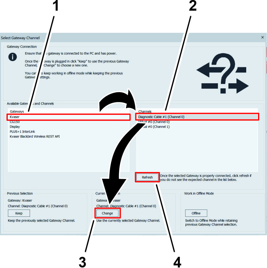
On the Select Gateway Channel screen, click the Kvaser option in the Gateways list.
-
In the Channels menu, click the Diagnostic Cable option.
Note: If a diagnostic cable option does not display in the Channels menu, verify that the Toro Diag cable is plugged into the USB port of the laptop computer, click the Refresh button on the Select Gateway Channel screen, and click the Diagnostic Cable option.
-
Click the CHANGE button under the Current Selection heading.
Product Overview
Enable/Transport Switch
Use the Autosteer enable/transport switch to enable the steering assist (Spray Mode) function or put the machine in transport mode.
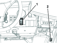
Engage/Disengage Switch
Use the Autosteer engage/disengage switch to engage or disengage the steering assist function.
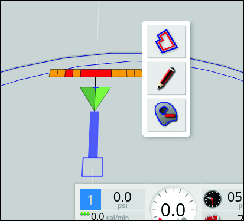
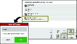
Figure 33 shows the engage/disengage switch displayed in the control console.
Operation
Understanding the Icons
The color of the icon changes with the state of the system.
| Icon color | Auto Steer State | Description |
|---|---|---|
 | Not engaged | Autosteer is not engaged and not active. Press the Autosteer steering wheel icon (Figure 33) to see the condition(s) preventing the system from engaging. |
| Red | ||
 | Delayed engage | While in the stopped position and near a guideline, press the Autosteer steering wheel icon twice (double click). Autosteer engages when the minimum speed is reached within 15 seconds. |
| Yellow | ||
 | Standby | The steering assist function is ready to use. |
| White | ||
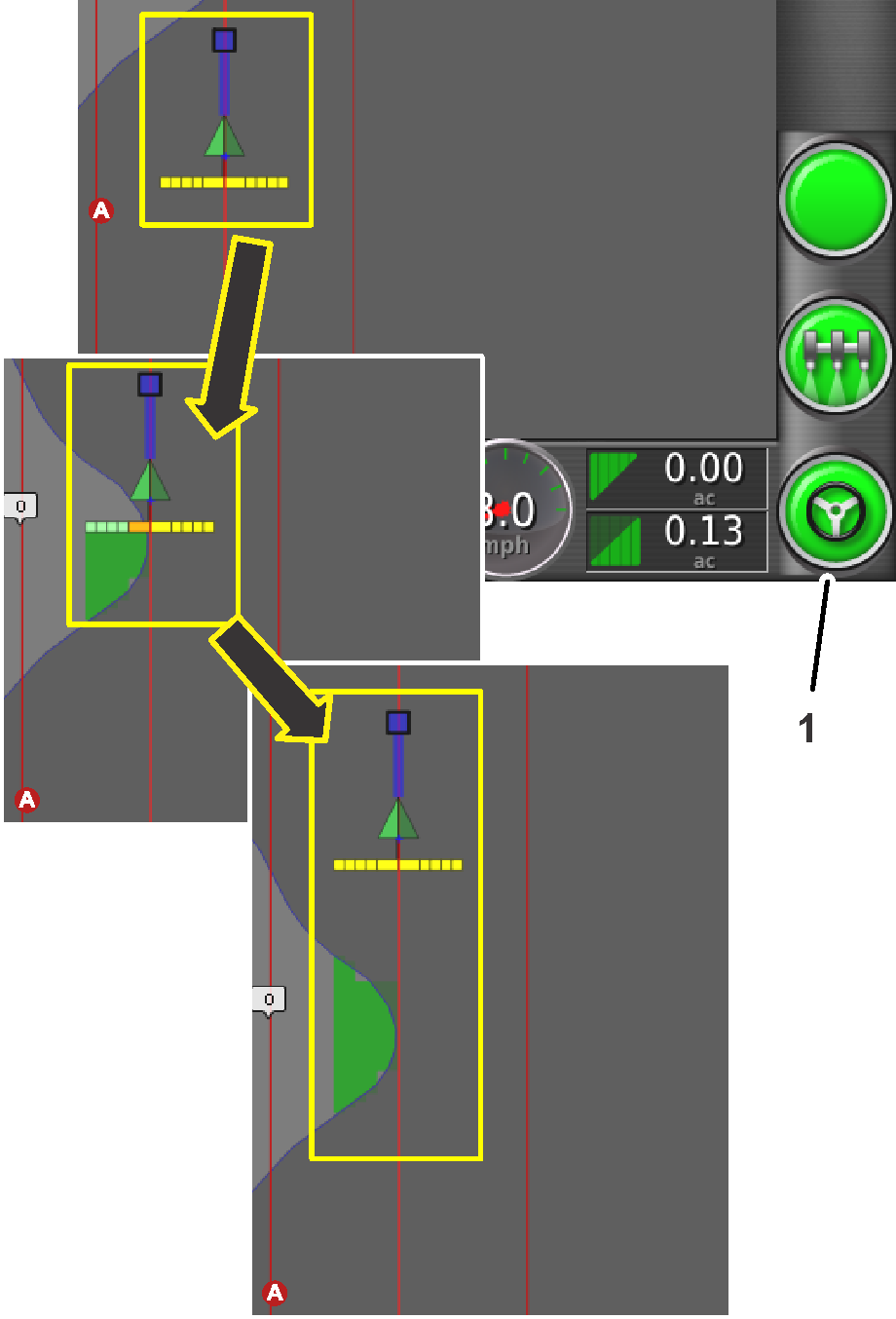
 | Engaged | Autosteer is engaged and active. Select the Autosteer steering wheel icon to return to manual steering mode. Note: The icon may briefly flash blue before turning green. |
| Green |
Understanding the Alarms
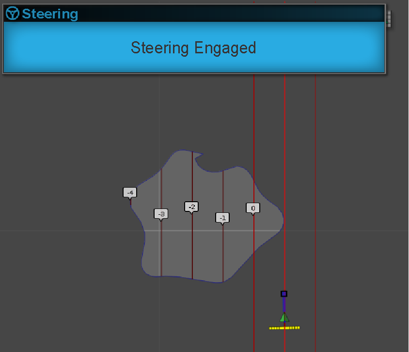
Visual alarms
-
STEERING ENGAGED—a visual alarm displays when the steering assist function engages (Figure 35).
-
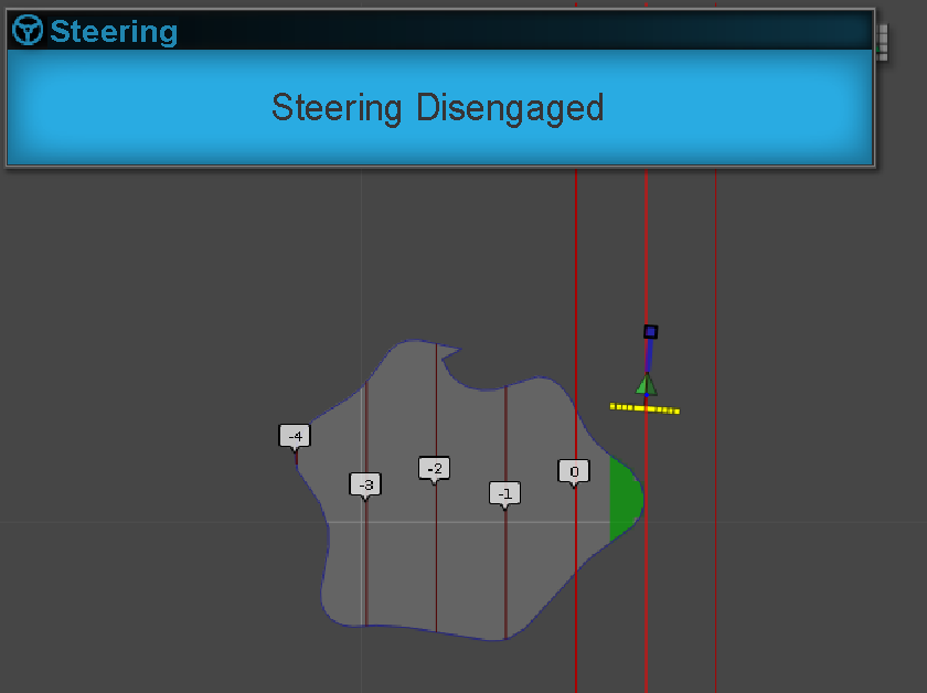
STEERING DISENGAGED—a visual alarm displays when the steering assist function disengages (Figure 36). The system may disengage because of the following causes:
-
Weak satellite signal.
-
The GPS system loses the guideline or a degradation of the RTK connection.
-
You manually turn the steering wheel.
-
Audible alarm
The audible alarm sounds when you disengage or engage the steering assist function.
Understanding the Steering Options Menu
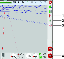
Using the Status Screen
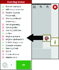
The status screen displays the conditions required for operating the machine with Autosteer.
-
The conditions marked with a green indicator are ready for operation.
-
The conditions marked with a red indicator show that the steering assist function is not ready for operation.
-
Navigate to the guidance toolbar and press the Autosteer icon.
-
Review the status of each condition in the list. Perform 1 of the following:
-
Press the Steering Alarm Icon at the bottom left of the screen to display the list of steering alarms.
-
Press the Steering Alarm information icon, the red button next to the confirm icon, to see detailed information regarding the steering alarms.
-
Press the Confirm icon to return to the main screen.
Important: Before using the steering assist function, complete the conditions with red indicators, working through the conditions from top to bottom in the status screen.
Steering Status Table
Condition Description when the condition displays in red: Receiver hardware Check that the receiver is connected and getting electrical power. Differential corrections The control console may not match the correction source requirements. Position accuracy The satellite receiver needs time for signal convergence. Check the number and color of the satellite icons on the control console. Drive the machine to a clearing with no overhead power lines. Steering controller Check that the controller is connected and getting electrical power. Vehicle geometry The vehicle geometry is incorrect. Select a new vehicle profile. Vehicle profile Check which vehicle is selected in the controller and check the geometry settings. Steering calibrated The steering needs to be calibrated; refer to your Toro Distributor or Toro’s NSN Service Center. Lockout The steering system is in transport mode, there is a fault with the wheel angle sensor, or the steering controller has reported an error. Guideline (wayline) available The machine is too far from the guideline—drive closer to the guideline. Check that the guideline is created and selected. Guideline (wayline) synchronized The guideline is not loaded. Check that the satellite receiver has a satellite signal and the receiver loads the guideline. It may take time to upload guidelines to a satellite receiver, particularly for large curved guidelines. Prohibited operation The system cannot engage when certain actions are performed, such as steering calibration, changing GPS settings, or exporting a job. Operator presence Sit in the operator’s seat. Steering wheel Loosely hold the steering wheel when engaging the steering assist function. Speed Drive the machine between 1 to 12.9 kph (0.7 to 8 mph). The required speed may vary by machine. Crosstrack error Drive the machine closer to the guideline before engaging the steering assist function. Heading error Check the angle or vehicle speed that the machine is traveling when approaching a guideline. Check the compass calibration. -
Using the Guidelines Menu
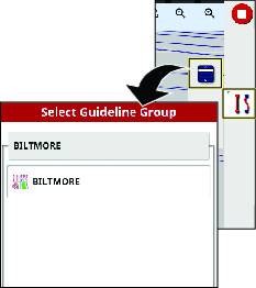
Displaying Programmed Guidelines
-
Press the guideline menu icon.
-
Press the select guideline menu.
Then select the AB line menu or the select curve menu appears.
-
For longer lists of guidelines, swipe the scroll bar to navigate the full list of guidelines.
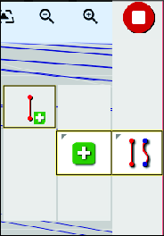
Creating a Straight Guideline
To create a guideline start by defining the starting point (point A) and the end point (point B). This AB line is used to establish the parallel guidelines to cover the whole field or a boundary.
-
Drive the machine to the starting point of a guideline.
-
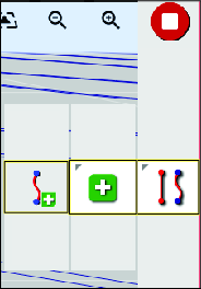
Press the guideline menu icon and press the add guideline icon.
-
Select the straight icon.
-
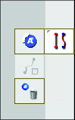
Press the set point A icon.
Point B will display in the control console.
-
Drive the machine to the other side of the field boundary to the location where you want the AB guideline to reference.
-
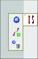
Press the set point B icon.
-
The console displays the options to rename or activate the new guideline.
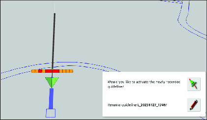
Note: The machine will drive straight at the end of a guideline.
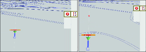
Creating a Curve Guideline
-
Drive the machine to the starting point of a guideline.
-
Press the guideline menu icon, press the add guideline icon, then the curved guideline icon.
-
Press the Set Point A icon.
Point B will display in the control console.
-
Drive the machine along the contour path of the field boundary.
The control console displays the path with a red line.
Note: Press the pause/resume recording icon to temporarily stop and start the recording of the path.
-
Press the Set Point B icon.
Note: The machine will drive straight at the end of a guideline.
Using Guidelock Guidance Mode
Guidelock guidance model generates a curve based on existing coverage.
Select the guidelock icon  on the top of the display .
Note: The black (or white) icon indicates that guidelock mode is off and the colored icon indicates that it is on.
Using boundary steering
Boundary steering creates a guideline inside the boundary and is offset by half an implement width away from the boundary. The offset width can be adjusted using the nudge menu.
Ensure that the guideline is a sufficient distance away from the boundary to avoid colliding with anything.
As the vehicle moves towards the center of the field, more guidelines are created. Guidelines are spaced one implement width apart.
To create a boundary, refer to your GeoLink Software Guide.
-
Enable boundary steering in the setup menu.
-
Press and hold to select the boundary on the display.
The boundary is highlighted on the display.
-
Select the boundary guideline icon from the popup menu.
Calibrating
Calibrating the Compass
Ensure that the GeoLink compass is calibrated, refer to the GeoLink Software Guide for your machine.
Enabling AutoSteer
-
Rotate the key to the ON position.
-
Start the X control console, and press the SETUP icon.
-
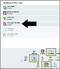
Press the SYSTEM icon, FEATURES icon, and the GUIDANCE icon.
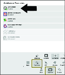
-
Press the AUTO STEER icon
 .
. -
In the dialog box, press the ENABLE icon, and press the confirm icon.
Setting the Steering Engage Value
-
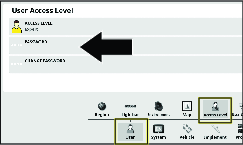
On the setup screen, press the USER icon, and the ACCESS LEVEL icon.
-
On the user access screen, ACCESS LEVEL icon.
-
In the dialog box, press the EXPERT icon, and press the confirm icon.
-
Press the PASSWORD icon, type the dealer password with the pop-up keyboard window, and press the confirm icon.
Note: The user access level displays dealer.
-
Press the VEHICLE icon, and press the STEERING icon.
-
Press the STEERING ENGAGE icon.
-
In the dialog box, press the VIRTUAL AND EXTERNAL CONSOLE INPUT icon, and press the confirm icon.
Calibrating the Wheel Angle Sensor
-
Move the machine to an open, flat area; clear of trees and buildings; and where you can drive the machine in a straight line for 92 m (300 ft).
-
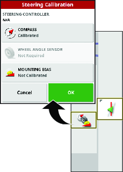
Press the STEERING OPTIONS icon.
-
Press the STEERING CALIBRATION icon.
-
Press the WHEEL ANGLE SENSOR icon.
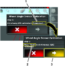
The wheel angle sensor calibration wizard starts.
Note: If a NOT INITIALIZED message displays in the control console, drive the machine for several minutes.
-
At step 1, wait until the wheel angle sensor calibration initializes, and press the next step icon.
-
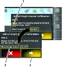
At step 2, fully turn the steering wheel to the left, stop, and press the next step icon.
Important: Verify that the wheel-angle sensor values change when the steer wheel turns.
-
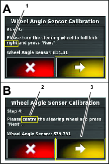
At step 3, fully turn the steering wheel to the right, stop, and press the next step icon.
-
At step 4, turn the steering wheel until the tires align straight ahead, stop, and press the next step icon.
-
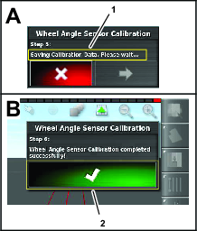
At step 5, wait until the wheel angle sensor calibration saves data, and press the next step icon.
-
At step 6, press the conform icon.
Calibrating the Mounting Bias for Auto Steer
Use this procedure to calibrate the receiver position on your machine. Calibrate the satellite receiver mounting bias when it is first installed or if the satellite receiver is replaced.
Note: For this calibration, you need a flat open area to drive a straight line for 76 m (250 ft) or more.
-
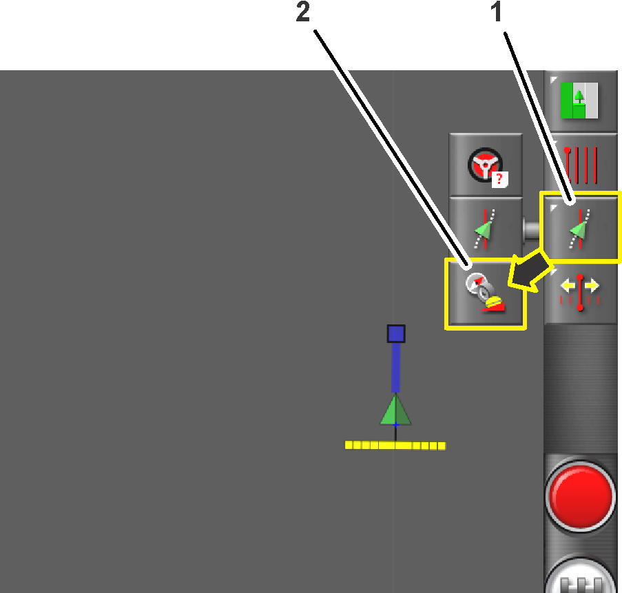
Press the STEERING OPTIONS icon.
The steering options menu displays.
-
Press the STEERING CALIBRATION icon.
The steering calibration menu displays.
-
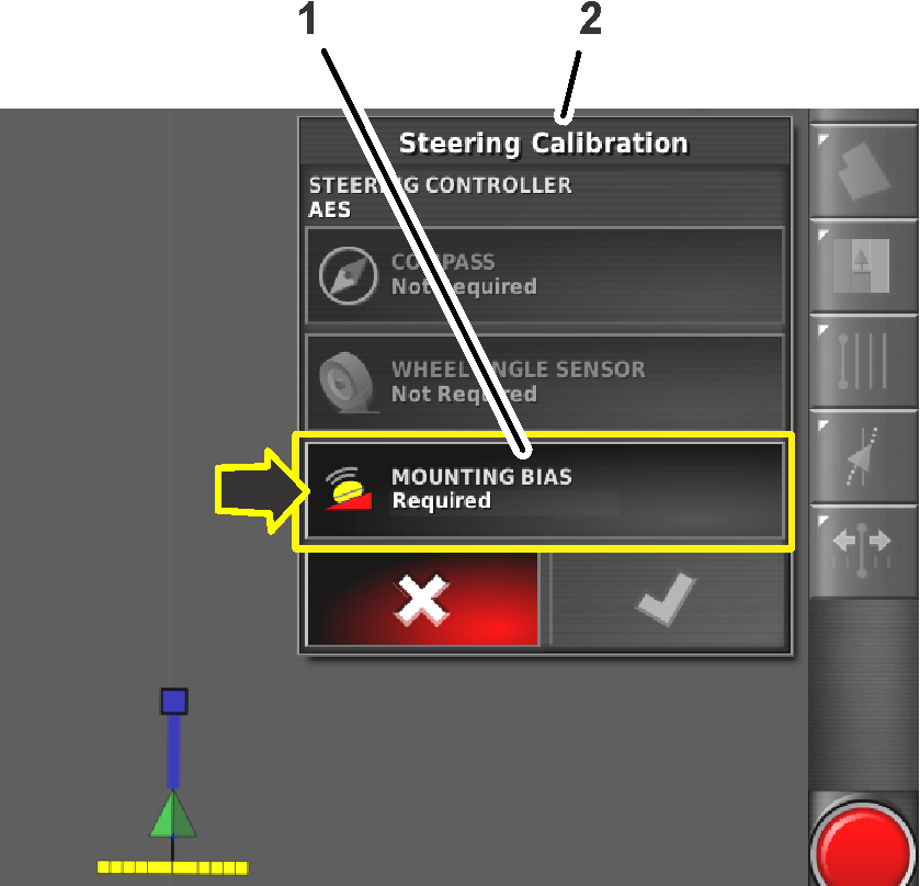
Press the MOUNTING BIAS icon.
The mounting bias calibration wizard displays.
Note: If the Mounting Bias icon indicates NOT REQUIRED, you do not need calibrate the mounting bias setting.
-
Drive the machine to the end of the open area, align it straight, and press the POSITION A icon.
Note: The point A symbol displays on the control console.
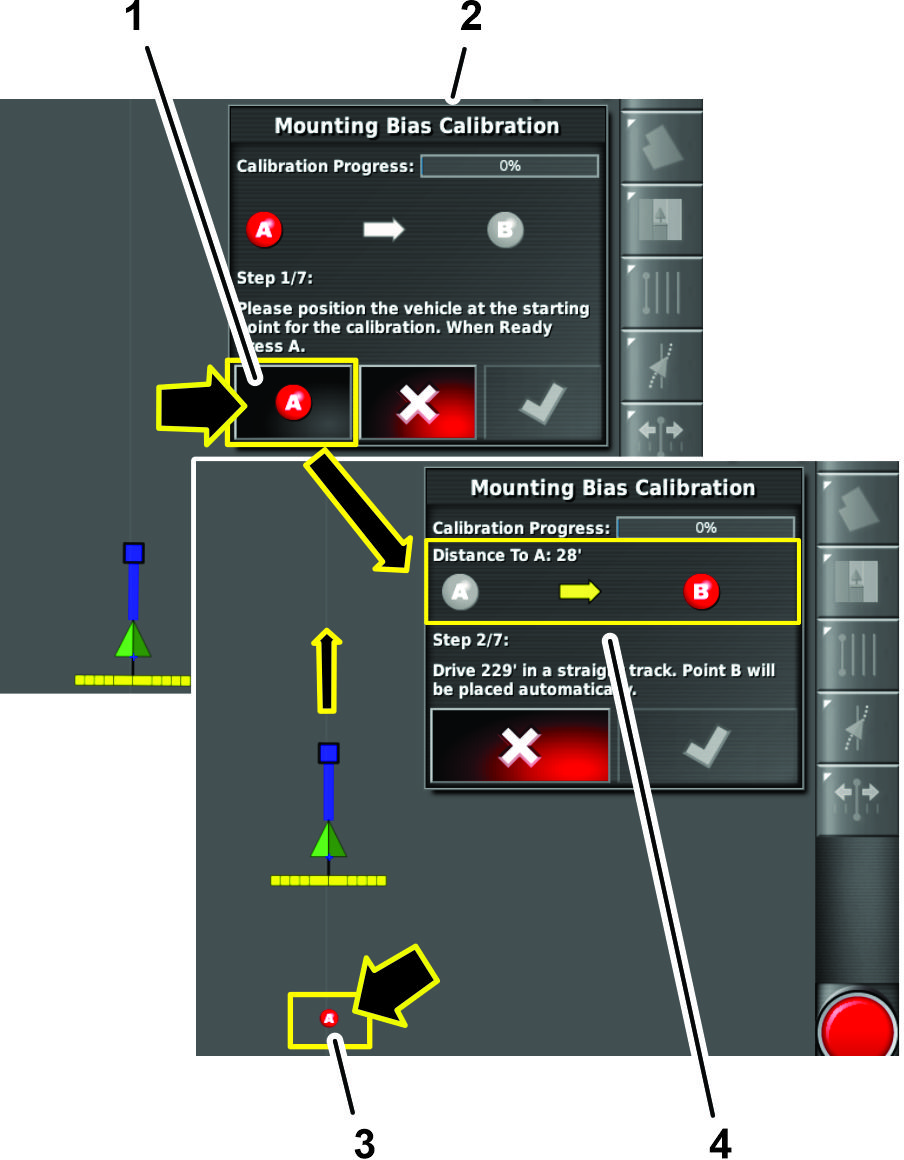
-
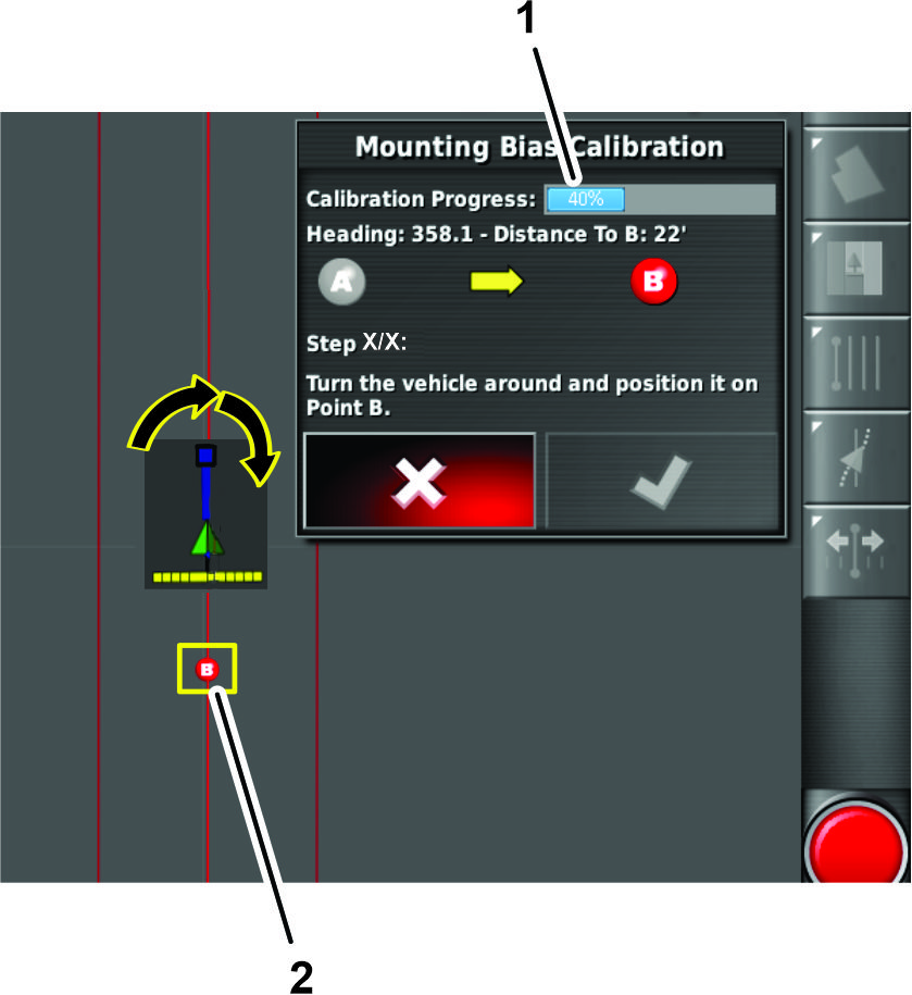
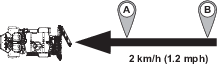
Manually drive the machine forward at 2 km/h (1.2 mph) in a straight line.
Note: GeoLink automatically inserts the point B symbol in the display when the machine travels 70 m (230 ft).
-
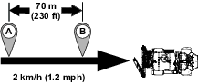
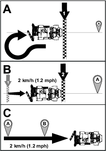
The command console displays the next screen of the calibration process.
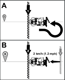
Turn the machine around, align it with the position A and B guideline in the control console.
-
Drive the machine toward point B and press the AUTO STEER icon
.Important: Allow the auto steer function to steer the machine.
-
Before reaching point B, set the ground speed for machine to 2 km/h (1.2 mph), and engage the throttle lock of the machine.
Note: Autosteer steers the machine between points B and A.
-
Stop the machine.
-
The command console displays the following:
-
The dialog box indicating 100% calibration progress, press the confirm icon.
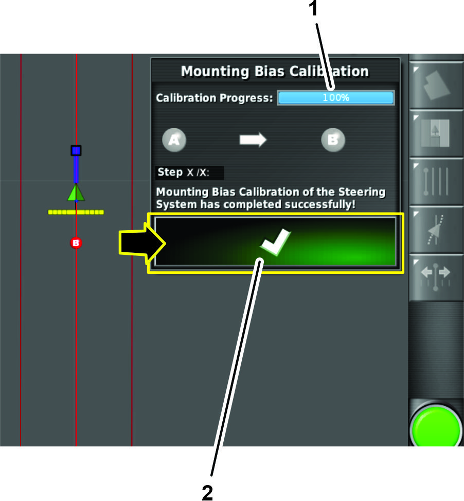
-
Dialog boxes with additional steps to perform a point A to point B mounting bias calibration pass.
Note: If the system does not indicate 100% calibration progress after performing the point A to point B mounting bias calibration pass, contact the Toro technical assistance center.
-
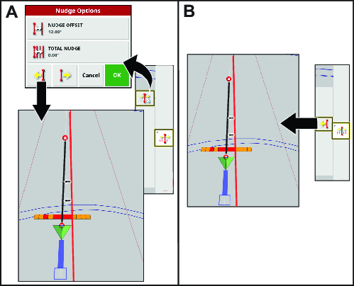
Using the Nudging Menu
Nudging the Guideline Position
The nudge icon creates a new guideline identical to the created guideline in a new location.
Press the Nudged Guideline icon and Nudge Options icon for nudge options.
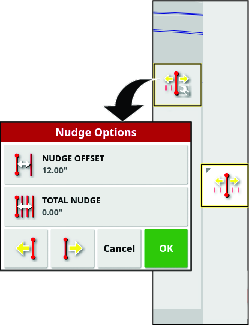
Use the nudge offset option to set how far the line will move.
Total nudge option displays the total distance nudged. Use the total nudge option to set a total nudge offset or to reset the nudge distance to 0.
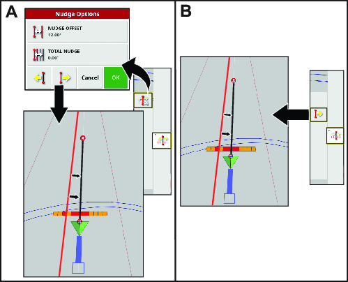
Nudging the Guideline to the Left
Nudging the Guideline to the Right
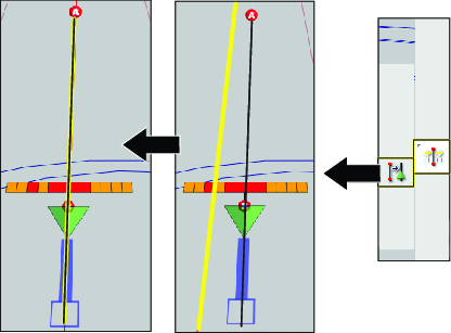
Setting a Nudged Line to the Vehicle Position
Drive to where you want the new line to be and press the nudge line to vehicle icon
Driving the Machine with Autosteer
Using Autosteer to Drive the Machine
-
Select a guideline.
-
Set the enable/transport switch of the machine to the SPRAY position.
-
Confirm that all steering status items, except for the speed status, are OK (colored green); refer to Using the Status Screen.
-
Zoom and pan the control console until the machine icon is sized and centered in the screen.
-
Drive the machine to the desired starting point of the active boundary that you intend to spray.
-
Confirm that the Autosteer icon in the lower right corner of the control console is colored white (standby)
 .
.Note: If the steering icon is red, correct the condition not met from the status screen.
-
Press the Autosteer icon in the lower, right corner of the control console or press the engage/disengage switch of the machine.
The Autosteer icon turns green and the machine steers toward the nearest guideline.
Important: The system is tuned to provide smooth engagement and transitions while operating; if you believe your system engages or transitions too abuptly, stop using the auto guidance function and contact Toro GeoLink Support at 1-844-GEOLINK (1-844-436-5465), or GeoLink@toro.com for customer service..
-
When the machine drives outside the boundary, disengage the auto guidance function by performing 1 of the following actions:
-
Select the Autosteer icon at the lower right corner of the control console.
-
Rotate the steering wheel left or right.
-
Press the Autosteer engage/disengage switch on the machine.
-
Stop the machine.
-
-
Align the machine for the next spraying pass with the next guideline displayed in the control console.