Installation
Preparing the Machine
-
Park the machine on a level surface.
-
Engage the parking brake.
-
Shut off the machine and remove the key.
-
Disconnect the negative battery cable; refer to the Operator’s Manual.
Routing the Wire Harness
Parts needed for this procedure:
| Wire harness | 1 |
| Jumper harness—GTI-EFI machines only | 1 |
| Cable tie | 10 |
| Push-mount fastener | 4 |
| Parallel edge clip with tie—1.8 m (6 ft) and corrugated steel bed only | 1 |
| Perpendicular edge clip with tie—plastic cargo bed only | 2 |
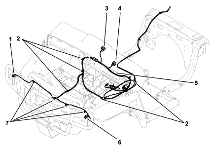
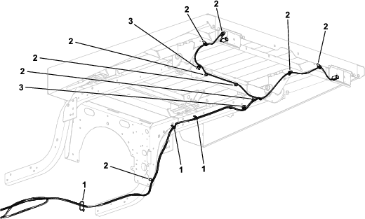
Routing the Harness to the Front of the Machine
-
Route and secure the wire harness as shown in the following figure.
-
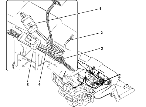
For models 07059TC, 07059LT, 07409, 07411EX only: Route and secure the jumper wire harness with a cable tie.
-
Install the connector labeled P02 to the connector labeled P01 in the light-kit wire harness.
-
Install the connector labeled P01 to the main harness.
-
Install the connector labeled J02 to the USB positive (+) connector.
-
Install the connector labeled J01 to the USB positive (+) wire.
-
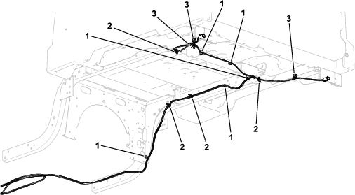
For Machines with a Plastic Cargo Bed Installed
Route and secure the wire harness as shown in Figure 3.
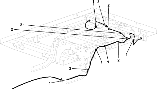
For Machines with a 1.8 m (6 ft) Steel Cargo Bed Installed
Route and secure the wire harness as shown in Figure 4.
For Machines with a Corrugated Steel Cargo Bed Installed
Route and secure the wire harness as shown in Figure 5.
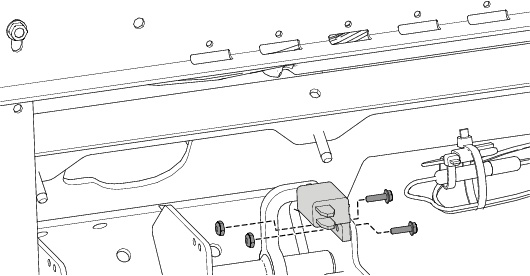
Installing the Brake Switch
Parts needed for this procedure:
| Brake switch | 1 |
| Hex-head screw (#6 x 1/2 inch) | 2 |
| Locknut (#6) | 2 |
-
Install the brake switch to the pedal assembly using the 2 hex-head screws (#6 x 1/2 inch) and 2 locknuts (#6) as shown in Figure 6.
Note: Ensure that the brake-pedal arm is aligned and makes contact with the brake-switch button when you release the pedal.
-
Verify the alignment and actuation of the switch by applying and releasing the brake.
-
Connect the wire-harness leads to the brake switch.
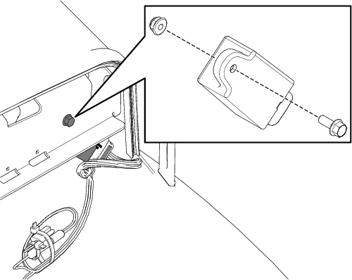
Installing the Flasher Module
Parts needed for this procedure:
| Flasher module | 1 |
| Hex-head screw (1/4 x 5/8 inch) | 1 |
| Locknut (1/4 inch) | 1 |
-
Install the flasher module to the dash reinforcement with the hex-head screw (1/4 x 5/8 inch) and locknut (1/4 inch) as shown in Figure 7.
-
Connect the wire-harness leads to the flasher module.
Installing the Signal Lights
Parts needed for this procedure:
| Front position/signal light | 2 |
| Front position/signal-light bracket—for machines with a Brush Guard Kit installed | 2 |
| Front position/signal-light bracket—for machines without a Brush Guard Kit installed | 2 |
| Self-tapping screw (1/4 x 1/2 inch)—for machines with a Brush Guard Kit installed | 4 |
| Rear brake/signal light | 2 |
| Taillight bracket—for machines with a 1.8 m (6 ft) steel cargo bed or plastic cargo bed | 2 |
| Phillips-head screw (#10 x 1-1/4 inches) | 8 |
| Locknut (#10) | 8 |
| Thread-forming screw (5/16 x 3/4 inch)—for machines with a 1.8 m (6 ft) steel cargo bed | 4 |
| Spacer (5/16 inch)—for machines with a plastic cargo bed | 2 |
| Flange-head bolt (5/16 x 3/4 inch)—for machines with a plastic cargo bed | 4 |
| Taillight bracket—for machines with a corrugated steel cargo bed | 2 |
| Carriage bolt (1/4 x 3/4 inch)—for machines with a corrugated steel cargo bed | 4 |
| Locknut (1/4 inch)—for machines with a corrugated steel cargo bed | 4 |
Installing the Position/Signal Lights
-
Remove the 2 existing screws from the headlight brackets (Figure 8).
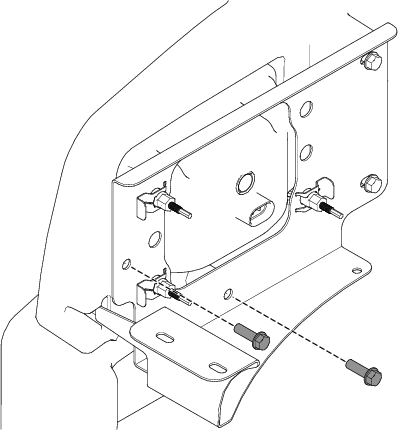
-
Secure the 2 front position/signal lights using the 2 front position/signal-light brackets, 4 Phillips-head screws (#10 x 1-1/4 inches), 4 locknuts (#10), and the previously removed 2 screws as shown in Figure 9.
Note: Ensure that the clear lens (position lights) are positioned to the inside and the amber lens (signal lights) are positioned to the outside.
-
Connect the 2 wire-harness leads to the 2 front position/signal lights.
Installing the Position/Signal Lights
-
Secure the 2 front position/signal lights to the brush guard using the 2 front position/signal-light brackets, 4 Phillips-head screws (#10 x 1-1/4 inches), 4 locknuts (#10), and 4 self-tapping screws (1/4 x 1/2 inch) as shown in Figure 10.
Torque the 4 self-tapping screws (1/4 x 1/2 inch) to 452 to 508 N∙cm (40 to 45 in-lb).
Note: Ensure that the amber lens (signal lights) are positioned on top of the clear lens (position lights).
-
Connect the 2 wire-harness leads to the 2 front position/signal lights.
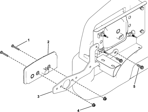
Installing the Brake/Signal Lights
-
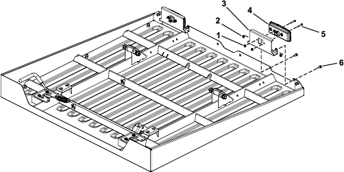
Secure the 2 rear brake/signal lights to the bottom of the plastic cargo bed and cargo-bed support using the 2 small rear brake/signal-light brackets, 4 Phillips-head screws (#10 x 1-1/4 inches), 4 locknuts (#10), 4 flange-head bolts (5/16 x 3/4 inch), and 2 spacers (5/16 inch) as shown in Figure 11.
Note: Ensure that the red lens (brake lights) are positioned to the inside and the amber lens (signal lights) are positioned to the outside.
-
Connect the 2 wire-harness leads to the 2 rear brake/signal lights.
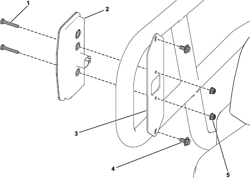
Installing the Brake/Signal Lights
-
Install the 2 rear brake/signal lights to the bottom of the 1.8 m (6 ft) steel cargo bed using 2 taillight brackets, 4 thread-forming screws (5/16 x 3/4 inch), 4 Phillips-head screws (#10 x 1-1/4 inches), and 4 locknuts (#10) as shown in Figure 12.
Note: Ensure that the red lens (brake lights) are positioned to the inside and the amber lens (signal lights) are positioned to the outside.
-
Connect the 2 wire-harness leads to the 2 rear brake/signal lights.
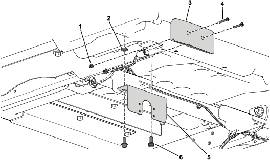
Installing the Brake/Signal Lights
-
Secure the 2 rear brake/signal lights to the bottom of the corrugated steel cargo bed using 2 taillight brackets, 4 Phillips-head screws (#10 x 1-1/4 inches), 4 locknuts (#10), 4 carriage bolts (1/4 x 3/4 inch), and 4 locknuts (1/4 inch) as shown in Figure 13.
Note: Ensure that the red lens (brake lights) are positioned to the inside and the amber lens (signal lights) are positioned to the outside.
-
Connect the wire-harness connectors on the lights to the main wire harness.
Installing the Turn-Signal Switch and Hazard-Light Switch
Parts needed for this procedure:
| Turn-signal switch | 1 |
| Hazard-light switch | 1 |
-
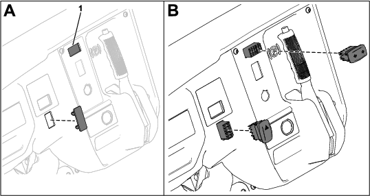
Cut out the opening in the dashboard decal for the turn-signal switch (box A of Figure 14).
-
Remove the plug for the hazard-light switch (box A of Figure 14).
-
Install the switch connectors through the openings in the dashboard (box B of Figure 14).
-
Install the switches to the switch connectors (box B of Figure 14).
Connecting the Battery
Connect the negative-battery cable; refer to your Operator’s Manual.
Checking the Function of the Lights
Checking the Function of the Brake Lights
Press your foot on the brake pedal and the brake lights should illuminate.
Checking the Function of the Signal Lights
Press the turn-signal switch to the left to engage the left signal lights.
Press the turn-signal switch to the right to engage the right signal lights.
Checking the Function of the Hazard Lights
Press the hazard-light switch to turn on the hazard lights.