Safety
Safety and Instructional Decals
 |
Safety decals and instructions are easily visible to the operator and are located near any area of potential danger. Replace any decal that is damaged or missing. |
Installation
Preparing the Machine
-
Park the machine on a level surface.
-
Engage the parking brake.
-
Lower the cutting unit.
-
Shut off the engine and remove the key.
-
Disconnect the battery; refer to the electrical system maintenance section of your Operator’s Manual.
Installing the Clips, Speed Nuts, and Fuse Block
Parts needed for this procedure:
| Switch mount | 1 |
| Clip (1/4 inch) | 6 |
| Speed nut | 2 |
| Fuse mount plate | 1 |
| U-type speed nut | 4 |
| Fuse block | 1 |
| Screw (#10 x 3/4 inch) | 2 |
Installing the Switch Mount
Parts needed for this procedure:
| Mount bracket | 2 |
| Carriage bolt (1/4 x 2 inches) | 4 |
| Locknut (1/4 inch) | 2 |
| Hex-head screw (1/4 x 3/4 inch) | 2 |
| Flange nut (1/4 inch) | 2 |
| Flasher | 1 |
| Relay | 1 |
| Wire harness | 1 |
| Cable tie | 2 |
| Fuse cover | 1 |
| Thumb screw | 2 |
| Push nut | 2 |
| Decal | 1 |
| Screw (#10 x 3/8 inch) | 2 |
| Multi-function switch | 1 |
| Hole plug | 3 |
| Rocker switch | 1 |
| Control cover | 1 |
| Hex-head screw (1/4 x 3/4 inch) | 6 |
| Switch clip | 2 |
| Push rivet | 2 |
-
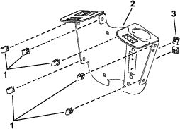
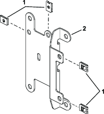
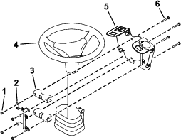
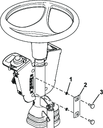
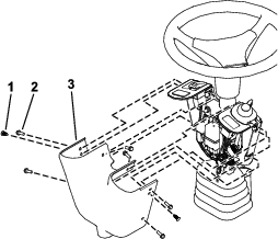
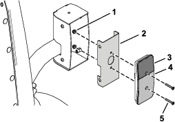
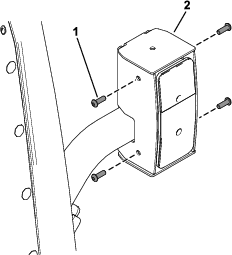
Loosely install the switch mount around the steering column using 4 carriage bolts (1/4 x 2 inches), 2 mounting brackets, fuse-mount plate, and 4 locknuts (1/4 inch) as shown in Figure 4.
-
Install the multi-function switch to the switch mount and secure it using the switch clips under the hole for the switch (Figure 5).
-
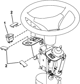
Install the rocker switch and hole plugs into the switch mount (Figure 6).
-
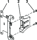
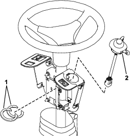
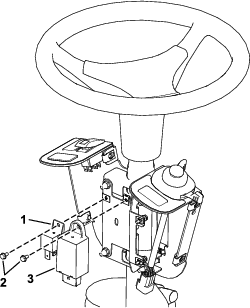
Install the flasher and relay to the fuse-mount plate using 2 screws (#10 x 3/8 inch) as shown in Figure 7.
-
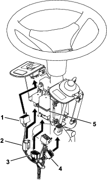
Secure the flasher using a cable tie (Figure 8).
-
Plug the harness into the rocker switch and multi-function switch (Figure 8).
-
Plug the wire harness into the relay and flasher (Figure 8).
-
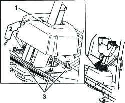
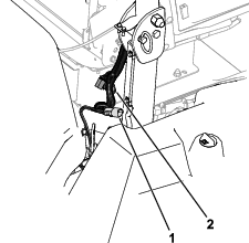
Loosen the bolts around the steering-column base (Figure 9).
-
Raise the base up and drill a 22 mm (7/8 inch) hole as shown in Figure 9.
-
Route the harness through the hole you drilled in the base.
-
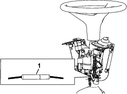
Connect the bullet connectors as shown in Figure 10.
-
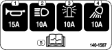
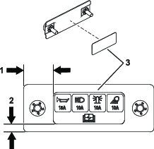
Apply the decal to the fuse cover as shown in Figure 11.
-
Install the fuse cover to the switch mount using 2 thumb screws and 2 push nuts (Figure 12).
Note: Ensure that the push nuts are installed on the inside of the fuse cover (Figure 12).
-
Adjust the control assembly so that the switches are accessible.
-
Tighten all the fasteners.
-
Install the control cover to the switch mount using 2 push rivets and 6 hex-head screws (1/4 x 3/4 inch) as shown in Figure 13.
Installing the Front Components
Parts needed for this procedure:
| Left light base (for machines with a cab) | 1 |
| Right light base (for machines with a cab) | 1 |
| Left light mount (for machines with a cab) | 1 |
| Right light mount (for machines with a cab) | 1 |
| Left light assembly (for machines with a cab) | 1 |
| Right light assembly (for machines with a cab) | 1 |
| Button-head bolt (1/4 x 5/8 inch)—for machines with a cab | 6 |
| Carriage bolt (3/8 x 3/4 inch)—for machines with a cab | 4 |
| Locknut (3/8 inch)—for machines with a cab | 4 |
| Light cross mount (for machines without a cab) | 1 |
| Yellow reflective tape | 2 |
For Machines with a Cab
-
Secure the left light base and right light base to the cab frame using 2 carriage bolts (3/8 x 3/4 inch) and 2 locknuts (3/8 inch) on each side.
-
Secure the left light mount and right light mount to the light bases using 3 button-head bolts (1/4 x 5/8 inch) through the speed nuts on each side.
Note: Ensure that you install the left light mount and right light in the most narrow mounting position.
-
Secure the left light assembly and right light assembly to the left light mount and right light mount using the hex nut on the light assemblies.
Note: Install the lights with the low beam toward the outer edge of the machine.Look at the bottom of the lights for high beam and low beam orientation.
-
Apply the yellow reflective tape to the left light base and right light base using the dimensions shown in below.
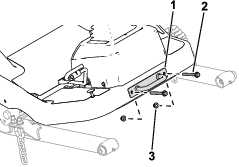
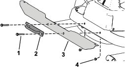
For Machines without a Cab
-
Remove the tie-down bracket from the platform.
Retain the parts.
-
Apply the yellow reflective tape to the light cross mount using the dimensions shown below.

-
Secure the light cross mount to the platform using the previously removed bolts, nuts, and tie-down bracket.
-
Secure the left light assembly and right light assembly to the light cross mount using the lock washer and hex nut on the light assemblies.
Note: Install the lights with the low beam toward the outer edge of the machine.Look at the bottom of the lights for high beam and low beam orientation.
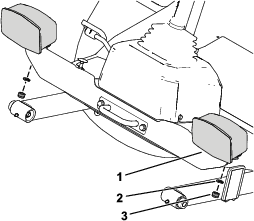
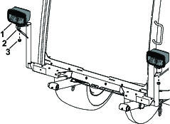
Installing the Rear Components
Parts needed for this procedure:
| Left mount | 1 |
| Right mount | 1 |
| Left short mount | 1 |
| Right short mount | 1 |
| Carriage bolt (5/16 x 3/4 inch) | 4 |
| Flange nut (5/16 inch) | 4 |
| Carriage bolt (1/4 x 5/8 inch) | 4 |
| Locknut (1/4 inch) | 11 |
| Hex-head bolt (3/8 x 3 inches) | 4 |
| Locknut (3/8 inch) | 4 |
| Red reflective tape | 4 |
| Marker mount | 1 |
| Back mount | 2 |
| Slow-moving vehicle sign | 1 |
| Flat washer | 3 |
| Flange-head bolt (1/4 x 3/4 inch) | 7 |
| Left light housing | 1 |
| Right light housing | 1 |
-
Remove the flange-head bolt (3/8 x 2-3/4 inches) and flange nut (3/8 inch) securing the bumper to the rear tube frame on each side of the bumper.
-
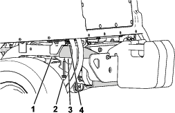
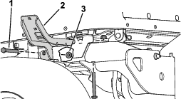
Secure the left mount and right mount to rear frame tubes using 2 hex-head bolts (3/8 x 3 inches) and 2 locknuts (3/8 inch) on each side.
-
Secure the left short mount and right short mount to the left mount and right mount using 4 carriage bolts (5/16 x 3/4 inch) and 4 flange nuts (5/16 inch).
-
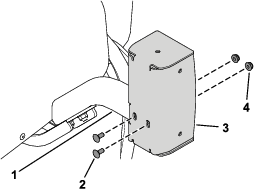
Secure the left light housing and right light housing to the left short mount and right short mount using 4 carriage bolts (1/4 x 5/8 inch) and 4 locknuts (1/4 inch).
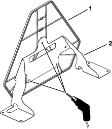
Warning
Using a drill without proper eye protection may allow debris to enter the eye, causing injury.
When drilling, always wear eye protection.
-
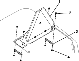
Using the marker mount as the template, drill 3 holes (5/16 inch) into the slow-moving vehicle sign.
-
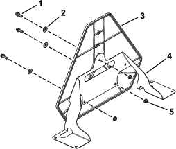
Secure the slow-moving vehicle sign to the marker mount using 3 flange-head bolts (1/4 x 3/4 inch), 3 flat washers, and 3 locknuts (1/4 inch).
-
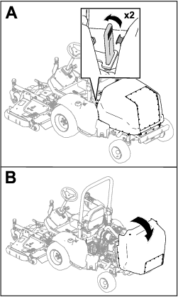
Remove the 4 plastic plugs from the hood.
-
Raise the hood.
-
Secure the assembled slow-moving vehicle sign to the hood using 4 flange-head bolts (1/4 x 3/4 inch), 2 back mounts, and 4 locknuts (1/4 inch).
-
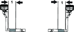
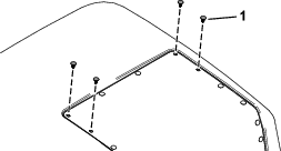
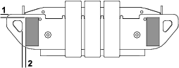
Apply 2 red reflective tape to the rear bumper and 1 reflective tape to each light housing using the dimensions in the figures below.

Routing the Light Wire Harness
Parts needed for this procedure:
| Light wire harness | 1 |
| Cable tie | 2 |
| Inner mount assembly | 2 |
| Taillight | 2 |
| Pan-head screw (#10 x 1-1/4 inches) | 4 |
| Flange nut (#10) | 4 |
| Button-head bolt (1/4 x 3/4 inch) | 8 |
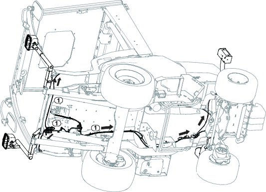
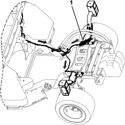
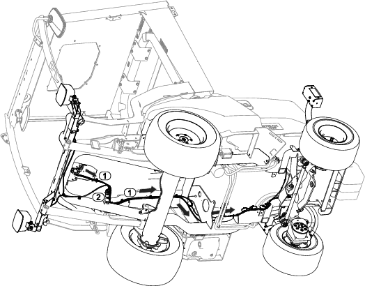
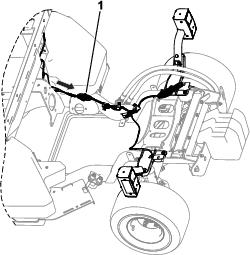
Refer to the following figures and instructions for routing the light wire harness.
-
Route the wire-harness connector labeled to the left side of unit. Connect harness to light.
-
Route the wire-harness connector labeled to the right side of unit. Connect harness to light.
-
Route the wire-harness connector labeled to the rear left side of unit.
-
Route the wire-harness connector labeled to the rear right side of unit.
-
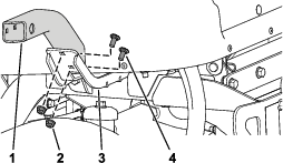
Secure the taillights to the inner mount assemblies using 4 pan-head screws (#10 x 1-1/4 inches) and 4 flange nuts (#10).
-
Connect the wire-harness connector labeled to rear light.
-
Connect the wire-harness connector labeled to rear light.
-
Secure the assembled taillights to the taillight housings using 8 button-head bolts (1/4 x 3/4 inch).
Ensure that you install the taillights with the yellow lens on top.
-
Use a cable tie coil the remaining connectors (J01 and J02) together.
Routing the Control Wire Harness
Parts needed for this procedure:
| Control wire harness | 1 |
Refer to the following figures and instructions for routing the control wire harness.
-
Connect the control wire-harness connector labeled TO ROAD LTS HARNESS (P06) to light wire-harness connector labeled TO MAIN HARNESS (P03).
-
Connect the control wire-harness connector labeled TO POWER HARNESS (P05) to power wire-harness connector labeled POD CONTROL HARNESS (P04).
-
Use a cable tie to coil the remaining connectors (J01 and J02) together.
Connecting the Battery
Connect the battery; refer to the electrical system maintenance section of your Operator’s Manual.