


Maintenance
Note: To obtain an electrical schematic or a hydraulic schematic for your machine, visit www.Toro.com.
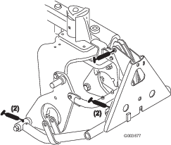
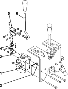
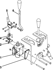
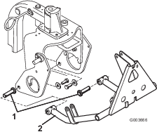
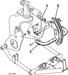
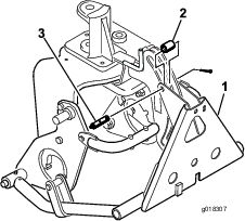
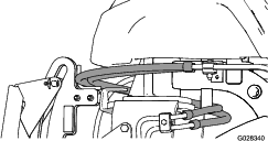
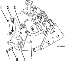
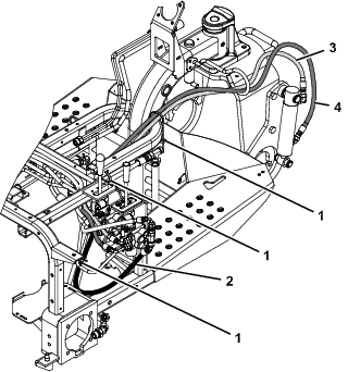
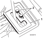
Greasing the Lift Frame
The front lift frame has 5 grease fittings (Figure 27) that must be lubricated regularly with No. 2 lithium grease. If the machine is operated under normal conditions, lubricate all bearings and bushings after every 100 hours of operation. Lubricate the bearings and bushings immediately after every washing, regardless of the interval listed.