Installation
Preparing the Machine
Refer to the Operator’s Manual for your machine.
-
Park the machine on a level surface and engage the parking brake.
-
Shut off the engine, remove the key, and disconnect the battery; refer to your machine Operator’s Manual.
Removing Existing Components
Remove the navigation receiver, antenna, and brackets from your machine.
Installing the Navigation Receiver
Parts needed for this procedure:
| Navigation receiver | 1 |
| Receiver mount (Multi Pro 5800) | 1 |
| Receiver mount (Multi Pro 1750) | 1 |
| Bolts (M5) | 4 |
| Washer | 4 |
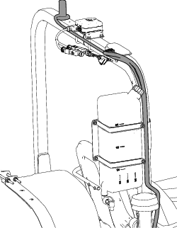
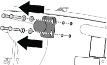
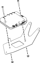
Installing the Navigation Receiver on the Multi Pro 5800 Machine
-
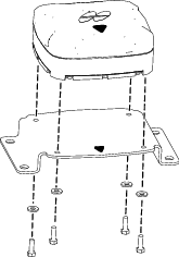
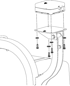
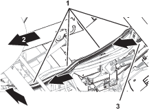
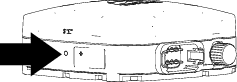
Secure the receiver to the receiver mount using 4 bolts (M5) and 4 washers.
Note: Ensure that both arrows are pointing toward the front of the machine.
-
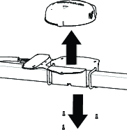
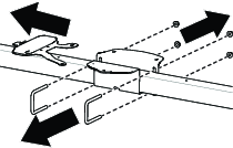
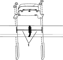
Line up the arrow on the receiver mount with the middle of the roll bar and secure the assembly onto the ROPS using the previously removed 4 U-bolts and locknuts.
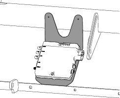
Installing the Navigation Receiver on the Multi Pro 1750 Machine
Secure the receiver to the receiver mount using 4 bolts (M5) and 4 washers.
Note: Ensure that both arrows are pointing toward the front of the machine.
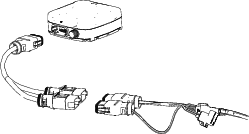
Installing the Harness Adapter
Parts needed for this procedure:
| Harness adapter | 1 |
-
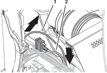
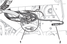
Route the 302 cm (119 inches) branch of the navigation-data and electrical harness along the right ROPS tube with the 12-socket connector (gray) and 12-socket connector (black) up toward the navigation receiver.
-
Connect the 2 connectors at the long face of the 12-socket connector of the data harness labeled with the 2 connector slots into the adapter harness.
-
Plug the adapter harness into the receiver.
Installing the Antennas to the Machine
Parts needed for this procedure:
| Antenna mount | 1 |
| High gain antenna (sold separately) | 1 |
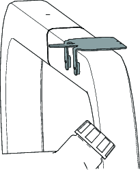
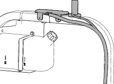
Installing the Modem Antennas
-
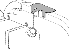
Install the modem antenna bracket to the roll bar.
-
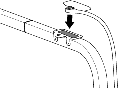
Clean any grease or oil from the antenna mount surface.
-
Remove the backing from the double sided adhesive liner and adhere the antenna to the mount.
-
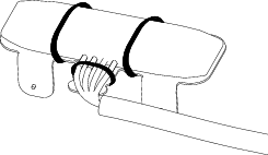
Secure the antenna and wire harness to the mount with 3 cable ties.
-
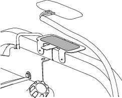
Place the high gain antenna on the roll bar.
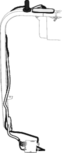
Routing the Modem-Antenna Harnesses (MultiPro 1750)
-
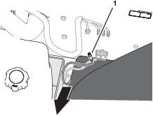
Route the modem-antenna harnesses to the right, along the roll bar.
-
Route the harness down and forward.
Routing the Modem-Antenna Harnesses (MultiPro 5800)
-
Route the modem-antenna harnesses to the right, along the roll bar.
-
Route the harness down and forward.
Installing the Display Bracket (Multi Pro 5800 only)
Parts needed for this procedure:
| Display bracket | 1 |
| Bolt (5/16 x 3/4 inches) | 4 |
| Nut (5/16 inch) | 4 |
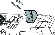
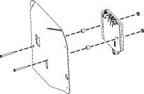
Installing the Ball Pivot Mount Bracket
-
Remove the existing display and ball pivot mount.
-
Assemble the bracket to the dash with the 4 bolts (5/16 x 3/4 inch) and secure it to the stiffener plate with 4 nuts (5/16 inch).
-
Loosely assemble stiffener plate with the 2 previously removed Phillips panhead screw (1/4 x 1 inch) and flange locknut (1/4 inch).
-
Torque the flange-head bolts, Phillips panhead screws, and flange locknut to 1163 to 1435 N∙cm (103 to 127 in-lb)
Mounting the Display
Parts needed for this procedure:
| Display | 1 |
| Ball mount | 1 |
| Display arm | 1 |
-
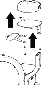
Assemble the ball fitting of the display and the ball mount on the machine to the long display arm.
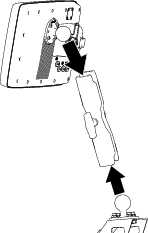
-
Adjust the display so that it is viewable from the machine operator’s position and tighten the display arm knob by hand.
Routing the Modem Data Harness
Parts needed for this procedure:
| Modem data harness—300 cm (118 inches) | 1 |
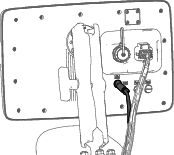
Connecting the Modem Data Harness to the Display
Screw the modem harness connector into the display.
Routing the Modem Data Cable (Multi Pro 5800)
-
Route the modem data cable through the storage compartment.
-
Route the modem data cable along the wire harness of the machine, and through the grommet in the floor plate.

-
Secure the modem data cable to the machine wire harnesses with 4 cable ties.
-
At the bottom of the machine, route the modem data cable rearward, along the wire harness of the machine.
-
At the rear side of the radiator, route the modem data cable upward.

-
Secure the modem data cable to the machine wire harnesses with 4 cable ties.
-
Route the modem data cable along the modem power harness, out the right side of the machine, and between the fuel tank bracket and the right, front fender.
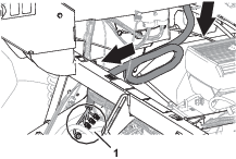
Routing the Modem Data Cable (Multi Pro 1750)
-
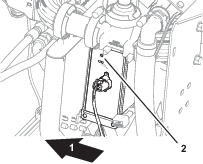
Route the modem data harness along the data harness for the display.
-
Route the modem data harness under the shock-support tube of the machine
-
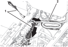
Route the modem data harness across the back if the relays and down.
-
Align the 4-pin connector labeled of the modem data harness near the 4 connectors for the modem-antenna harness as shown.
Installing the CL-55 Modem
Parts needed for this procedure:
| CL-55 modem | 1 |
Installing the Modem to the Machine (MultiPro 5800)
-
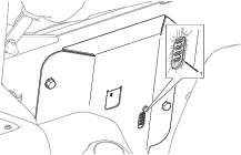
Secure the modem to the bracket using 2 bolts (#10 x 1-3/4 inch), 2 spacers, and 2 locknuts (#10)
-
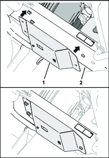
Place the modem bracket to the right seat-box panel over the bolt heads.
Important: Ensure that the wire harnesses are routed within the modem bracket.
Installing the Modem to the Machine (MultiPro 1750)
-
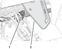
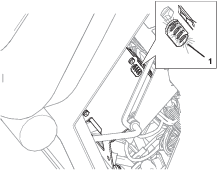
Remove the push-in fastener that secures the wire harness of the machine to the prop-rod bracket.
-
Secure the modem to the bracket using 2 bolts (#10-24 x 1-3/8 inches) and 2 nuts (#10-24).
-
Place the modem bracket under the prop-rod bracket and behind the flange of the machine frame.
Connecting the Antenna Harness to the Modem
-
Plug the coaxial connector of the modem-antenna harness labeled into the coaxial port of the CL-55 modem marked WIFI/BT, and tighten the coaxial connector.
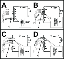
-
Plug the blue coaxial push-in connector of the modem-antenna harness labeled into the connector of the CL-55 modem marked , until the connectors latch securely.
-
Plug the violet coaxial push-in connector of the modem-antenna harness labeled into the connector of the CL-55 modem marked , until the connectors latch securely.
-
Plug the red coaxial push-in connector of the modem-antenna harness labeled LTE-2 into the connector of the CL-55 modem marked 4G DIV, until the connectors latch securely.
Connecting the Modem Data and Power Harnesses to the Modem
-
Plug the 4-pin connector of the modem data harness labeled into the 4-socket connector (unmarked) of the CL-55 modem, and tighten the knurled nut of the 4-pin connector.
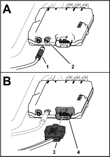
-
Plug the 18-socket connector of the modem power harness labeled into the 18-pin connector of the CL-55 modem.
Powering the GeoLink Components
-
Connect the battery; refer to your machine Operator’s Manual.
-
Turn the ignition key to the ON position.
-
Verify that the following components indicate that each receives power:
-
Control console—displays graphics and text

-
Satellite receiver—the PWR indicator illuminates
-
Modem—the LED indicators illuminate.
-
Automatic section controller—the STATUS indicator illuminates
-
-
Turn the ignition key to the OFF position.
-
Verify that power is shut off at the following components:
-
Control console
-
Satellite receiver
-
Automatic section controller
-
Completing the Software Setup
Refer to the Software Guide for version 5.02 and up.