Important: You must have the Multi-Tool Attachment (Model No. 08854) and the Box Blade Attachment Holder (Model No. 08861) installed prior to installing the field edger.

Warning

CALIFORNIA

Proposition 65 Warning

Use of this product may cause exposure to chemicals known to the State of California to cause cancer, birth defects, or other reproductive harm.

Safety

Safety and Instructional Decals

Graphic

Safety decals and instructions are easily visible to the operator and are located near any area of potential danger. Replace any decal that is damaged or missing.

decal133-8061
decal145-7411
decal145-1779
decal145-1778

Installation

Preparing the Machine

  1. Park the machine on a level surface or move the machine to a machine lift.

  2. Engage the parking brake.

  3. Raise the mid-mount attachment. Insert the depth control pin into the position to keep the mid-mount attachment up.

  4. Shut off the engine and remove the key.

  5. Wait for all moving parts to stop and machine components to cool.

  6. Chock the wheels or raise the machine with a machine lift.

Assembling the Edger

Parts needed for this procedure:

Edger assembly1
Edger disc1
Disc guard1
Locknut (1/2 inch)2
Carriage bolt (1/2 x 1-1/4 inch)2
  1. Remove the installed disc mounting bolt (5/8 x 1-1/2 inches), washer, and retaining disc from the edger assembly.

  2. Install the disc to the edger assembly using the previously removed disc mounting bolt, washer, support disc, and retaining disc as shown in Figure 1 and Figure 2; tighten the bolt to 203.4 N⋅m (150 ft-lbs).

    Important: When tightening the bolts, secure the edger disc shaft from rotation using the wrench flats.

    Important: Ensure that the beveled edge of the support disc is contacting the interior curve of the edger disc.

    Note: The edger disc is reversible, it can be installed for edging sidewalks or for edging garden beds; refer to Adjusting the Edger Disc.

    g519108
    g519142
  3. Align the disc guard with the proper holes according to the disc orientation (Figure 3).

    g408024
  4. Install the disc guard to cover the edger disc using the included carriage bolts (1/2 x 1-1/4 inch) and locknuts (1/2 inch) as shown in Figure 4.

    g519129

Installing the Edger

Parts needed for this procedure:

Edger assembly1
Stop pin2
  1. Secure the edger to the box blade attachment holder with the included stop pins as shown in Figure 5.

    Note: Ensure that the edger is installed with the disc guard above the disc and the disc trailing the multi-tool.

    g388457
  2. If you want to install the edger to the other side of the machine, remove carriage bolts and locknuts securing the disc guard, and flip the edger so the disc is in position for use on the other side of the machine.

  3. Install the disc guard to the top of the edger using the previously removed carriage bolts and locknuts as shown in Figure 4.

    Note: The disc guard must cover the cutting edge of the disc. Refer to 4 for instructions on how cover the disc with the guard.

Operation

Adjusting the Edger Angle

The angle of the edger relative to the machine is adjustable; set the edger angle so the trailing edge of the disc is contacting the sidewalk, and the leading edge of the disc is a slight distance away from the sidewalk.

Note: A higher edger angle results in a more aggressive cut.

Note: Adjust the angle edger for forward travel, do not edger in while the machine is in reverse.

  1. Loosen, but do not remove, the locknut securing the disc mount in position on the track.

  2. Move the disc left or right along the track, using the decal to gauge the exact position.

  3. Tighten the locknut to secure the disc mount in the new position.

    g388460

Adjusting the Edger Disc

The edger disc is reversible; it can be installed with either side facing out.

Install the disc with the convex side facing out for edging sidewalks, or install the disc with the concave side facing out for edging garden beds.

When switching from one orientation to another, also switch the position of the disc guard so that it covers the disc; refer to Assembling the Edger.

g388644

Maintenance

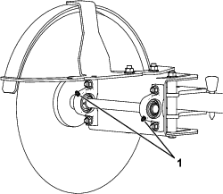
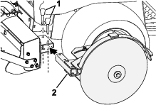
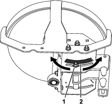
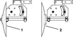
Greasing the Bearings

Maintenance Service IntervalMaintenance Procedure
Every 50 hours
  • Grease the bearingsor after every washing.
  • Grease Specification: No. 2 lithium grease

    1. Wipe the grease fittings clean.

    2. Pump grease into the fittings.

    3. Wipe off excess grease.

    Note: Improper wash-down procedures can negatively affect bearing life. Avoid directing high-pressure or high-volume spray at the bearings or seals.

    g388458